Wild Card

Week 15

Assignments

  • Design and produce something with a digital fabrication process (incorporating computer-aided design and manufacturing) not covered in another assignment, documenting the requirements that your assignment meets, and including everything necessary to reproduce it. Possibilities include (but are not limited to):

After the local lecture with our instructors and realizing different available machines in Fab Lab Oulu including Water Jet Cutter, Vacuum forming, Digital Embroidery, Sand Blasting for engraving, and Composites, I decided to try Vacuum forming process.

Vacuum Forming Process

The vacuum forming process works involves heating a plastic sheet until soft and then draping it over a mould. A vacuum is applied sucking the sheet into the mould. The sheet is then ejected from the mould. To see the process in action, watch the following video:

Mold design in Fusion 360

After a quick search on google for ideas, I came up with a boat design which I found a nice tutorial for that and followed it. During this design, I got familiar with a couple of more features in Fusion 360 including loft and Sweep. Figure 1 shows a summary of the design process.

Figure 1. Desinging process in Fusion 360.

After checking the design file with Ari, the week's instructor, he warned me about the size of the model that might not fit in the machine's plate. So, I had to modify the dimensions and rescale the model in order to have a maximum 4.5 cm height. The next steps were similar to what I did during Week 7: Computer-Controlled Machining . After fixing the model, I set the toolpath by selecting 8mm Flat and mill tool.

Figure 2. Selecting tool for milling.

Then, set the origin to be left front corner of the design with the X and Y axes along with the size surface. During the milling process, we found that the design were wrong, so Figure 4 shows the correct design.

(a)

(b)

Figure 3. Setting the origin.

Then, I checked the settings in 3D milling and noticed in Height tab that the bottom height was not defined. So, I went to Bottom Height->From and changed it to Selection, then, selected the bottom surface (Figure 4b shows the modified design).

(a)

(b)

Figure 4. Defining Bottom Height in 3D milling setting

From ACTIONS->Simulate, you can find the machining time (Figure 5) (Figure 4b shows the modified design).

(a)

(b)

Figure 5. Simulating the milling process in Fusion 360

Finally, from Post Process and choosing the right configuration folder to generate cnc file for the design.

Mold preparation

With the help of Ari, I found a couple of fil faced plywood board with around 1.5 cm thickness, while my design height was around 4.5 cm. So, I took four of those board and then, I had to cut two of them to have approximately equal lengths of the boards.

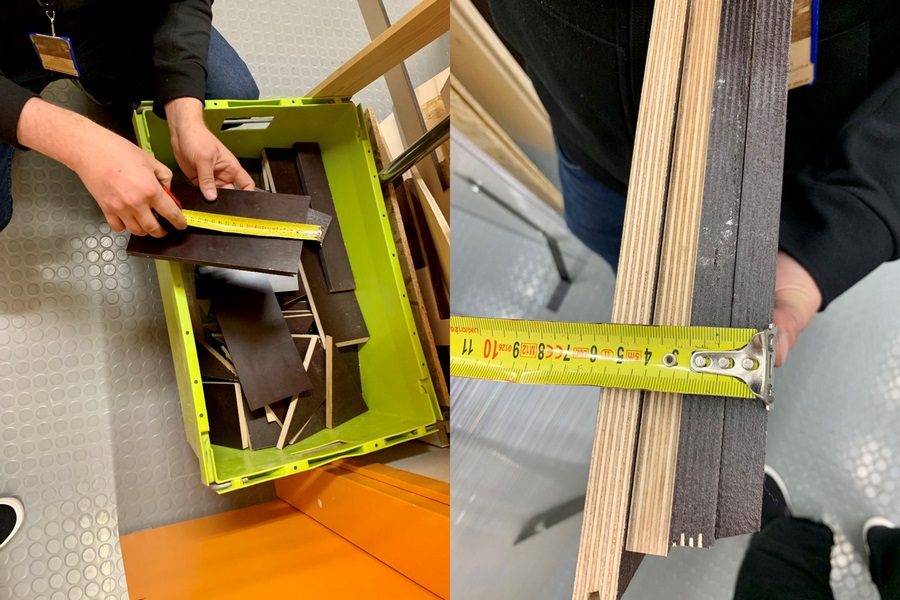
Figure 6. Finding the right size of the material

Then, I used the circular saw for the first time. It is scary but very simple to use:) Just do not forget safety issues (goggles and hearing protection)!

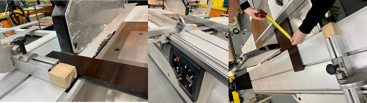
Figure 7. Working with circular saw to cut the boards

Next, I should glue four board together with wood glue and let it dry.

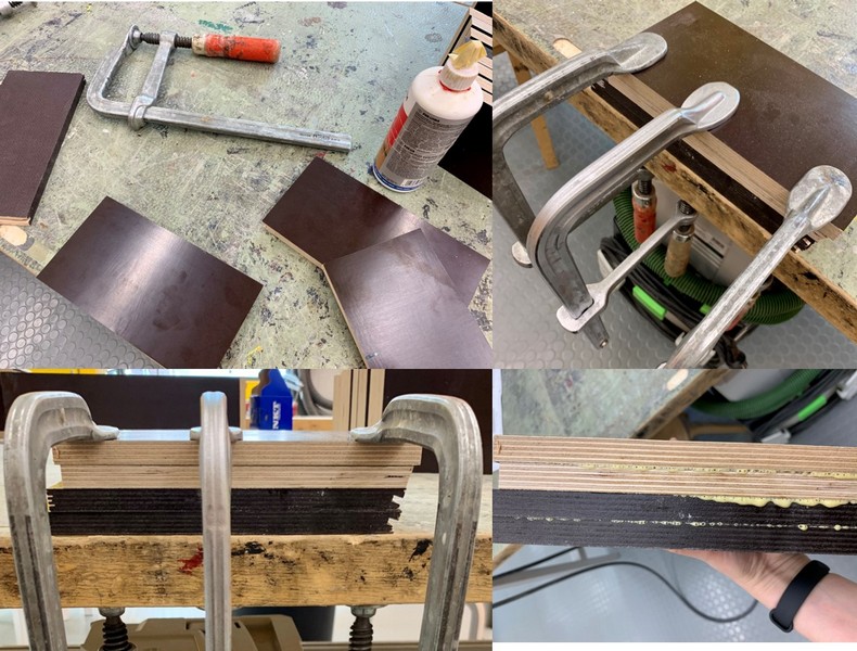
Figure 8. Glue the four board together

The mold material was ready to mill after one day when the glue completely dried. Then, I needed to screw the board to the CNC Router table.

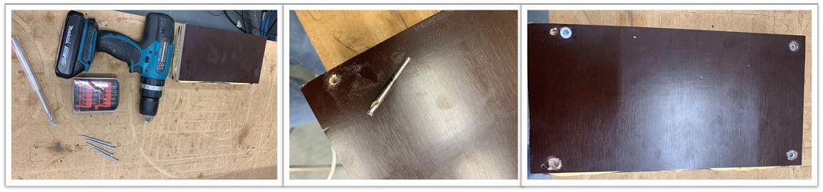
Figure 9. Fixing the mold material to the to the CNC Router table

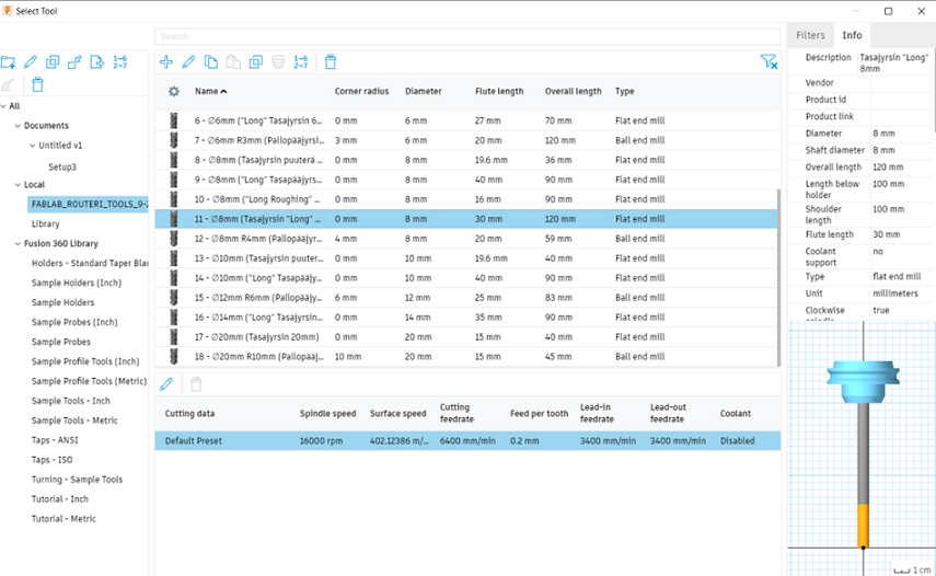
As I had chosen the milling bit as 8 mm flat and mill, I took the right bit to install on the machine jog.

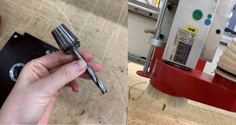
Figure 10. Installing the correct milling bit

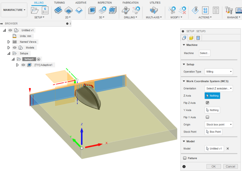
The steps for setting the origin and start the machine were explained in details in Week 7. During this stage, Ari noticed the design dimensions are not correct and it was still big and also, he suggested to remove the bottom board. So, I had to rescale it again and then, start milling.

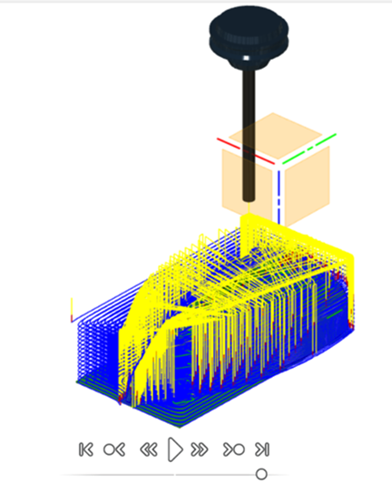
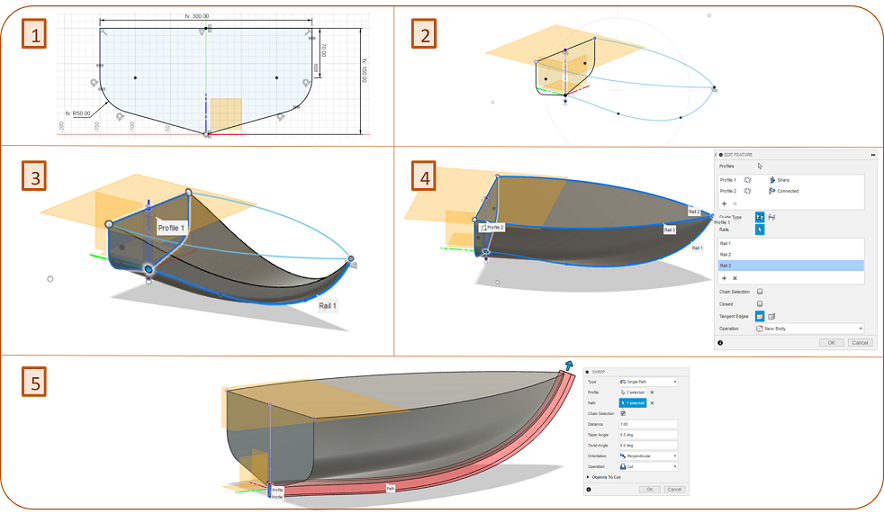
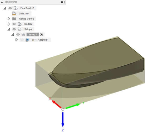
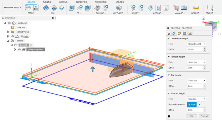
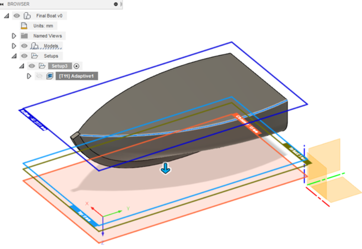
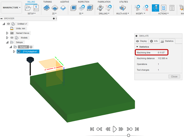
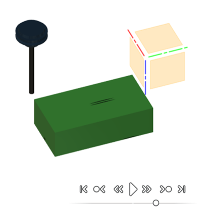
Figure 11. Final desing simulation after rescaling

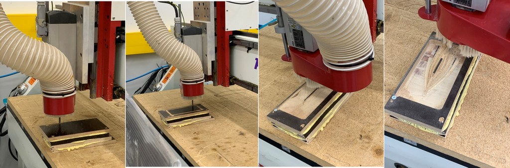
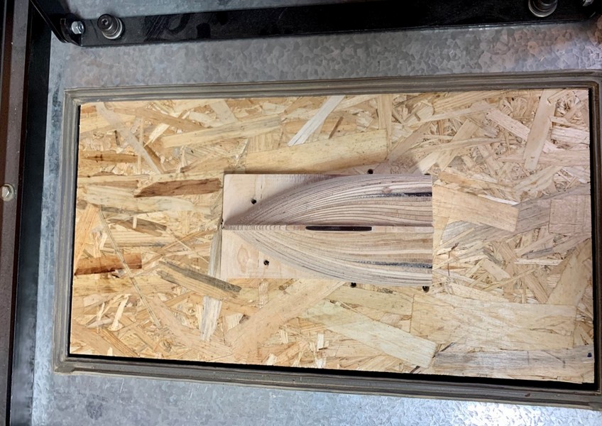
Figure 12. Milling the mold with CNC Router

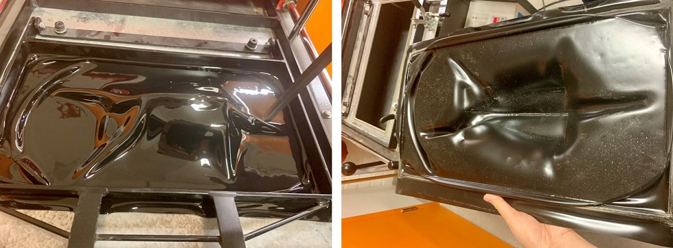
When milling was done, I did a couple of post-processing steps to make it completely ready for vacuum forming machine.

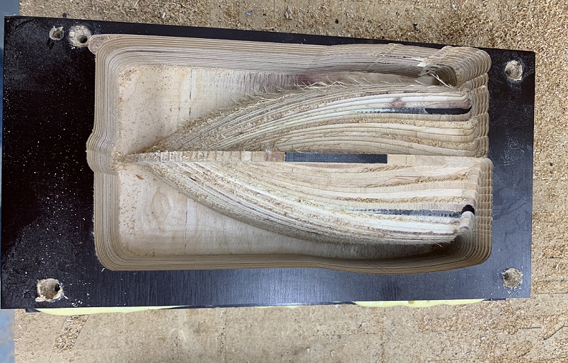
Figure 13. The mold after milling

First, I used the band saw to cut extra parts of the mold.

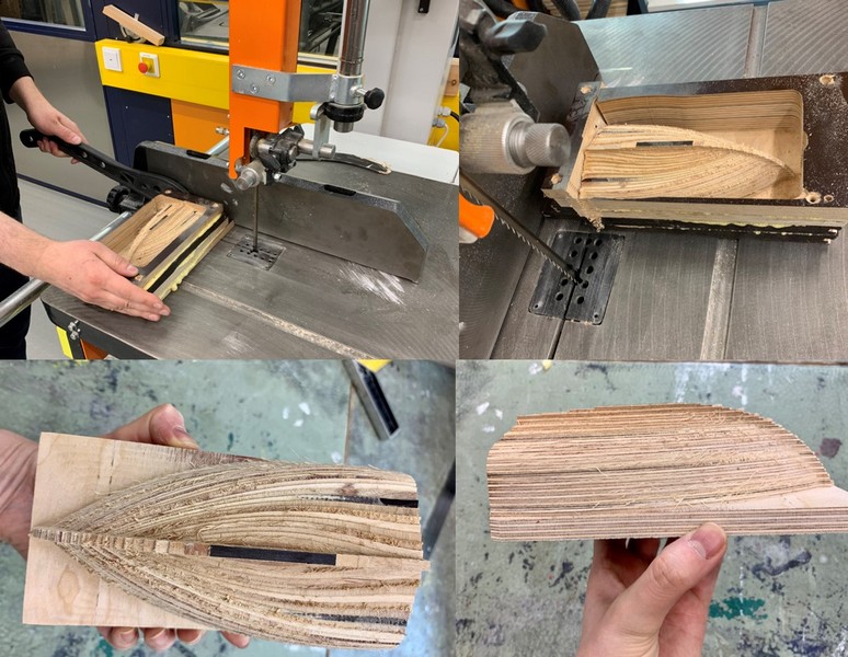
Figure 14. Cutting the extra parts of the mold with saw

Next, I cut another board with the size that fit the machine's plate using circular saw for the mold support and make the vacuum around the desired area and glued it to the bottom of the mold.

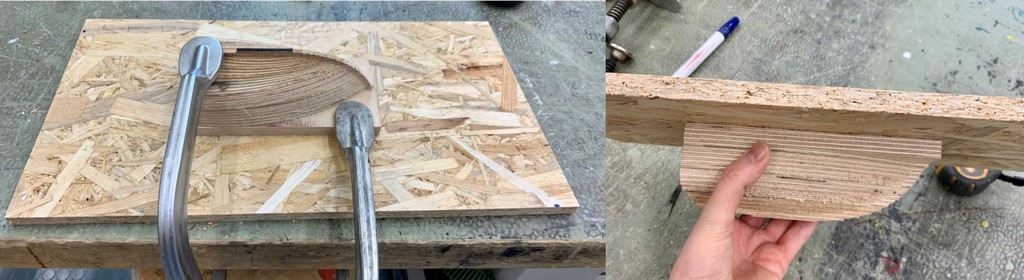
Figure 15. Making the support board for the mold

Then, I made holes around the mold for vacuum and Ari suggested to try bench drill machine for that.

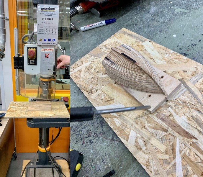
Figure 16. Making vacuum holes on the mold

Finally, it perfectly fit inside the machine's plate.

Vaccuum forming machine

The machine we have in Fablab Oulu was Vacuum Former 750FLB which is very simple to use.

First I put the mold inside the vacuum former and then, took a 2 mm polystyrene (PS) sheet to put in the frame for heating (Figure 19)

Figure 19. Putting the material in the vacuum former

The operation process is as the following (you can find the manual here):

  • First, lower the clamp frame and lock the toggle clamps and push forward the heater canopy. Then, switch on at the socket and the green Mains Indicator will illuminate.
  • Next, set each of the heat regulators to Full. The approximate heating time depends on the type of sheet you use and you can find the table of that on the machine. For 2 mm PS as it is shown in the picture, the heating time is 60 minutes but as Ari told me, as long as the material is softened, you can start vacuuming.
  • You can check the sheet time to time by pushing back the heater canopy. When it is ready, set the Energy Regulators to off with power to the machine and switch on the vacuum pump, you will be able to hear it running.
  • Slide the heater hood fully forward to the stop and return to the idling (fully back) position, to make sure there are no obstructions to the slide track.
  • Pull the Platen Elevating Handle down, towards the front of the machine until it clicks into the over-centre locked position.

Well, here, I had to do it twice while everytime I got different problems:) First time as you can see in the picture, the sheet was not heated enough, so it cooled down quickly and the material could not go properly around the mold edges.

The second time, it was overheated and was too soft so it made extra wrinkles:(

It was not perfect but at least, I got the idea and as Ari suggested, it would be better to make more vacuum holes on the mold. Also, it might work better with MDF than with OSB. The plastic sheet is thick, so the vacuum needs to be really good.

Reflection

During this week, I got familiarized with vacuum forming process which I had not tried that during the last week. Depend on the application and type of the material, it can be a simple and fast method to make object from your design. I can consider this method to make some components of the mechanical parts of my final project.

Mona Peyvasteh

Fab Academy 2021

Diary of my journey to the world of Digital Fabrication