Assignments
Group Assignment- probe an input device's analog levels and digital signals
Week 10
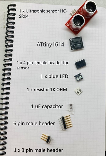
Figure 1. List of components used for the new pcb
Then, I started to create schematic in KiCad with the experience I gained from Week 6 (Electronic Design) while I learned a couple of shortcuts used in KiCad from Antti Mäntyniemi.
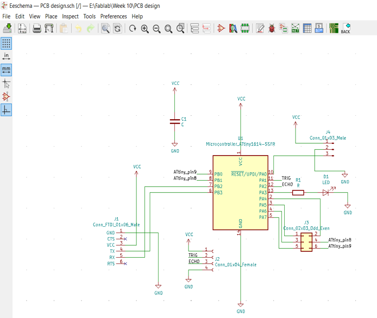
Figure 2. Schematic of the new board in KiCad
For the reference to figure out how to connect the components, I used ATtinyX14 pinout map:
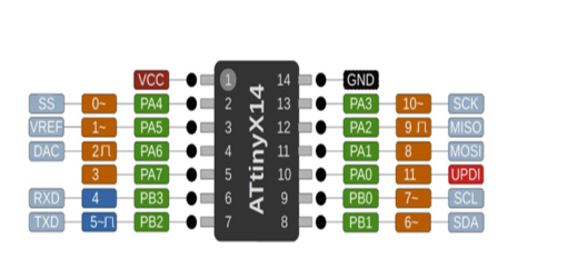
Figure 3. ATtinyX14 pinout
After clicking Run Pcbnew, I noticed theres is some error in assigning footprints, so checked it again and found that one symbol has not been assigned yet (Figure 4).
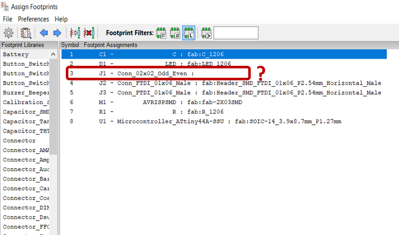
Figure 4. Error in assigning footprints
So, I assigned it from Footprint Libraries->fab, then, from Filtered Footprints and finally,Applied, Save Schematic & Continue as shown in Figure 5 and continued.
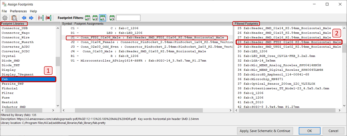
Figure 5. Assining the correct footprint from the selected library
Then, I clicked Update PCB from schematic and then, start wiring which was a bit tricky and needed to move or rotate the components.
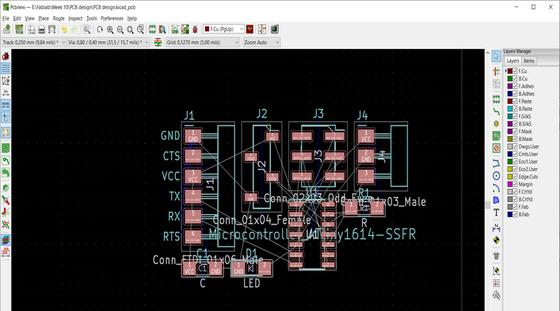
Figure 6. Update PCB from schematic in KiCad
According to previous experiences and my groupmate advice, I modifed the clearance and track width values.
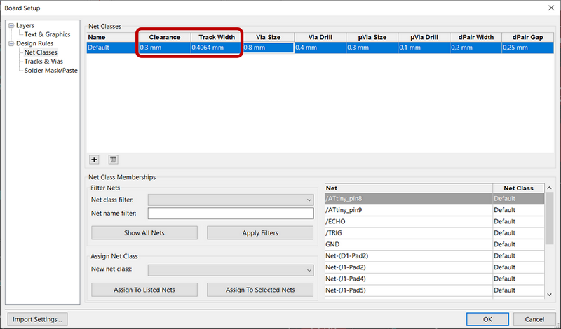
Figure 7. Editing board setup
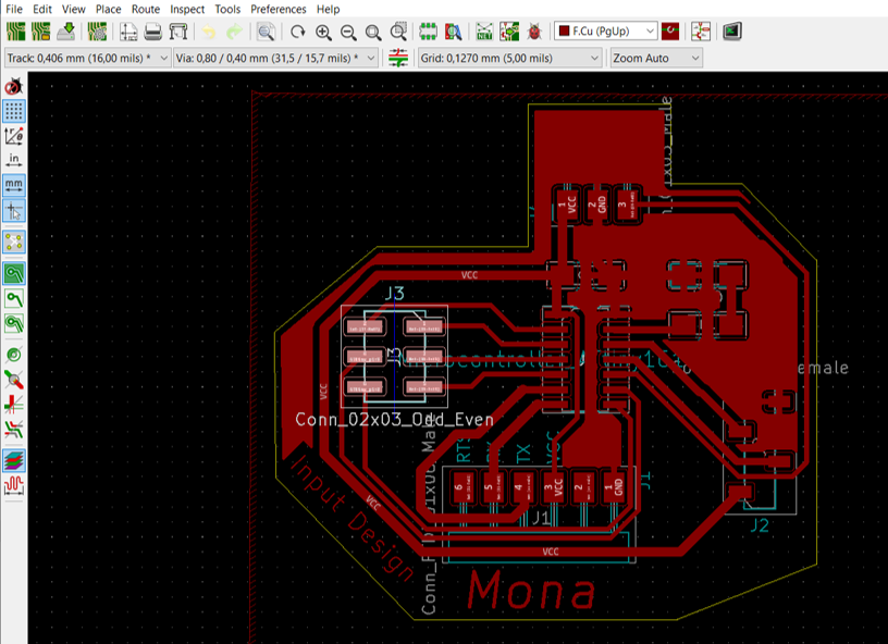
Figure 8. Final PCB design in KiCad
Then, for milling the board with LPKF milling machine, I needed Gerber (.gbr) format of the Schematic file, so I opened Plot and chose only F.Cu and Edge.Cuts layers and plotted which generated .gbr files of both.
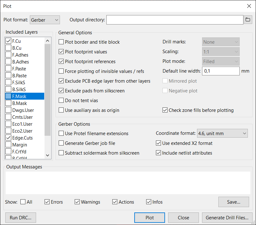
Figure 9. Converting .kicad-pcb to .gbr
Next, I started milling with LPKF milling machine Protomat S62 while contoling the machine with CircuitPro software (see more details in Week 6- Electronics Design).
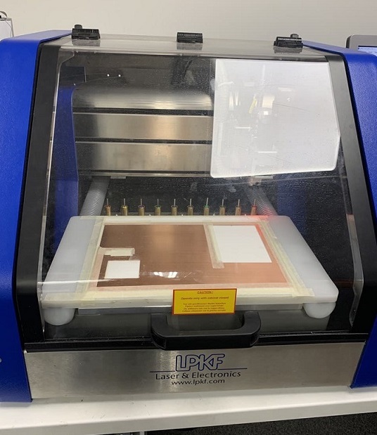
Figure 10. LPKF milling machine chamber, table and milling bits
Milling the board with LPKF machine
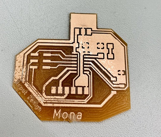
Figure 11. Final milled board
Then, it was soldering time that I am not much interested into that!:D
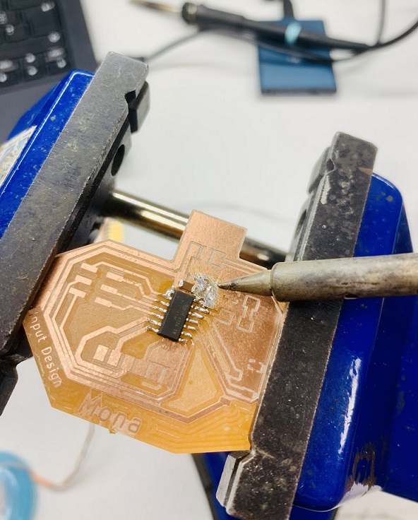
Figure 12. Soldering the components to the milled board
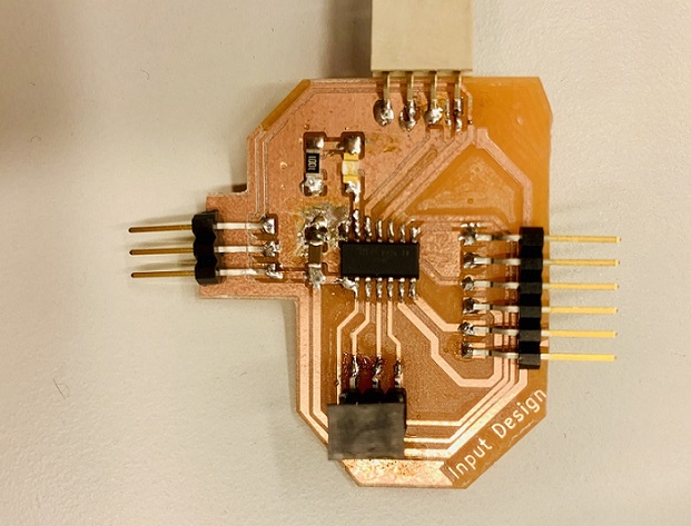
Figure 13. Final soldered board
The HC-SR04 ultrasonic sensor uses sonar to determine distance to an object like bats do. It offers excellent non-contact range detection with high accuracy and stable readings in an easy-to-use package. It comes complete with ultrasonic transmitter and receiver modules.
Figure 13 shows HC-SR04 ultrasonic sensor pinout: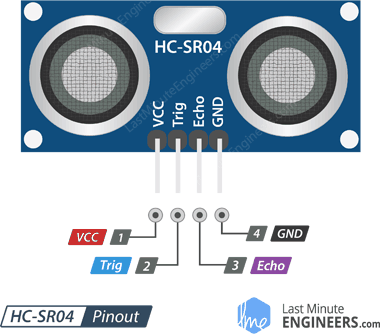
Figure 14. HC-SR04 ultrasonic sensor pinout [ref.]
VCC is the power supply for HC-SR04 Ultrasonic distance sensor which we connect the 5V pin on the board.
Trig (Trigger) pin is used to trigger the ultrasonic sound pulses.
Echopin produces a pulse when the reflected signal is received. The length of the pulse is proportional to the time it took for the transmitted signal to be detected.
GND should be connected to the ground of the board.
To test the board I made, I used the programmer board I made in Week 4 (Electronics Production).
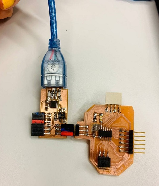
Figure 15. Final soldered board
Then, I tried to attach the sensor to the connecotr and start programming but my groupmate, Antti, noticed that I have soldered a wrong pin female header because of the type of header I had selected in schematic which was odd-even (Figure 16)!:( Well, clearly, I am totally new to this world and those mistakes are part of the learning process (I hope so!:D).
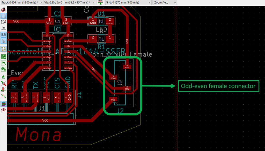
Figure 16. The type of header in shcematic
So, I had to detach the wrong header and solder the correct one:
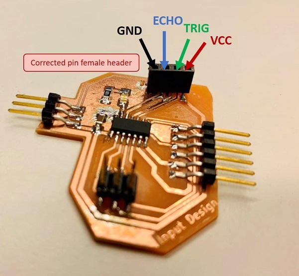
Figure 17. The modified board with the correct female header
When the board was ready, I started to conncet the sensor to the board considering the schematic of the board and the right pins for GND, VCC, TRIG and ECHO.
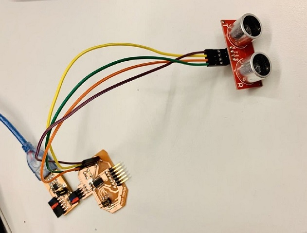
Figure 18. The connections between the programmer board, ATtiny1614 board and the ultrasonic sensor
For programming, I used Adrain's page and used his code as the sample while changing the pins for EchoPin to 9 and TriggerPin to 8.
