Input devices
Week 11
Like every week I started the week planning the assignment.
Group assignment. Probing an input device's analog levels and digital signals.
I usually do the group assignments individually as I am a remote student and none of my colleagues are in the fab academy, but in this case, we decided to meet the four of us (Leon remote students) and do some group assignments together.
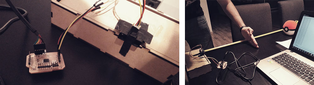
To measure a digital signal we decided to use the PCB that I designed in the Electronic design week and we loaded a blink sketch that turns on/off the LED each one second. First, we tried with a Semoic Mini ARM DSO212 Osciloscopier, but for some reason, when we connected to the boards it was giving us weird readings, creating short circuits and some times it gots frozen.
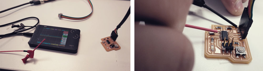
So we decided to use another oscilloscope, a Dso sheel one that Alejandro Ulecia assembled, and then we finally got the feedback of the digital signal from the PCB.
To probe the analog levels we decided to use the PCB that I designed for a phototransistor in the Input devices week. and after regulating the range of signal that the oscilloscope shows in the screen we got the feedback.
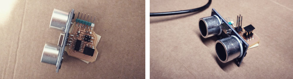
Distance input device: Ultrasonic sensor HC-SR04
For this assignment, I wanted to try some sensors that I could use for my final project. Since I want that my lamp reads the presence of the user, I thought it would be a good idea to try a distance sensor, so maybe the lamp would be able to know if someone or something is in front of it.
Additionally, I also thought it would be a good idea to add a BUS connector so I can use this board for the networking and communications week, so, having as a reference the Szilárd A. Kados's assignment, I decided to use an ITtiny44 microcontroller because of the extra communication connector pins.
The components that I used for this boards are:
> 1 x ATtiny44
> 1 x 10kΩ resistors
> 1 x 1uF capacitor
> 1 x 2x3 pin header (ISP)
> 1 x 2x2 pin header (BUS)
> 6 x Male headers (FTDI)
> 1 x Ultrasonic sensor HC-SR04
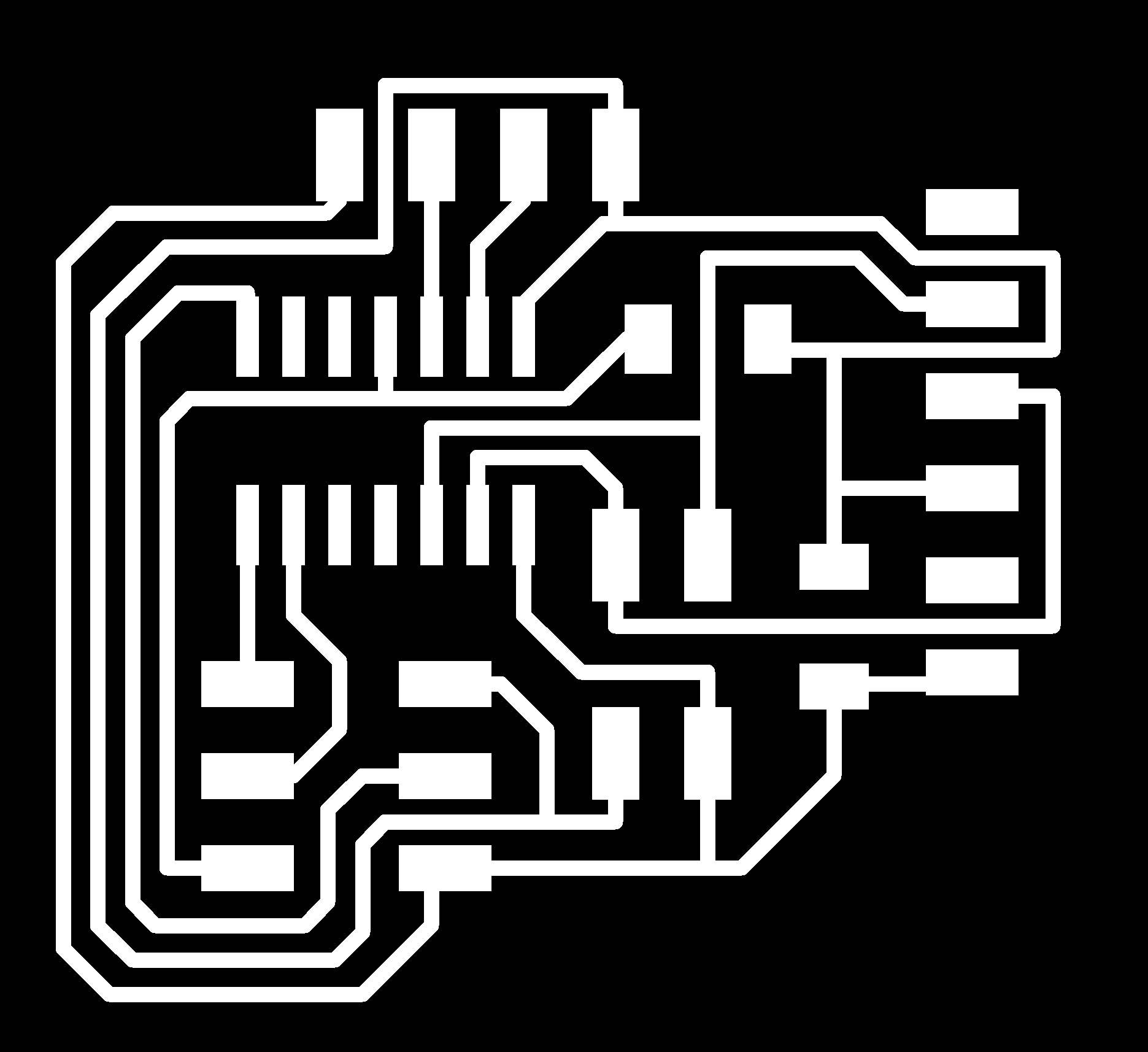
I designed the PCB in Eagle. I created a new schematic, I added all the components and I made all the connections. Then I created a board file from it, I checked the design rules and I arranged all the components and traces.
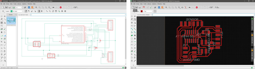
I couldn't find the sensor HC-SR04 in the libraries so I added an extra FTDI since they have the same footprint but just with 4 pins. I renamed the pins in the schematic according to the sensor pins and then in Photoshop I erased the extra two pines.
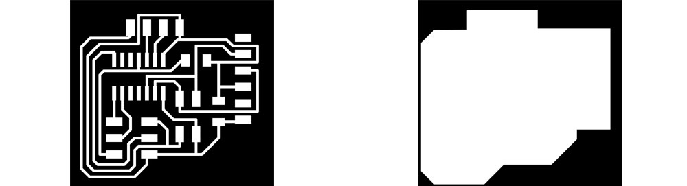
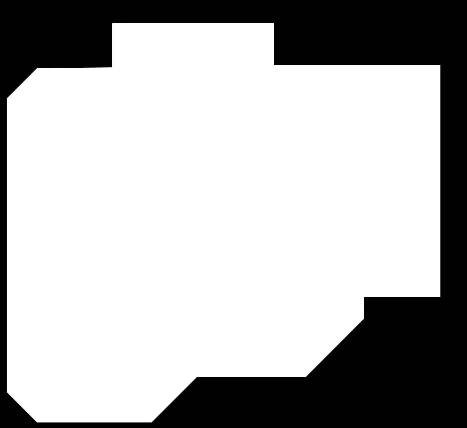
Then I exported the images for the traces into .png, I got the .rml files through Fab Modules and then I milled the PCB. The first attempt didn't go well. I had to level the base of the machine because in some areas the end-mill didn't cut all the way thought of the copper layer, but after that, the milling part went quite smoothly, without any incident and the board came out nicely.
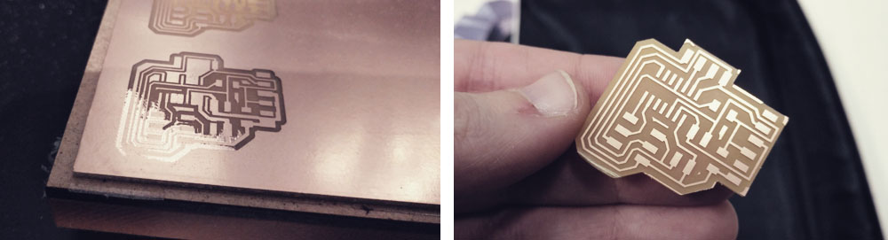
Then I soldered all the components and I checked with the multimeter that all connections were good.
It is quite easy to lose the reference of the scale while working in Eagle. I didn't realize how tiny was the board until it was cut and I started soldering. This time this process was a bit hard as I hadn't to much space to work. Mental note: make bigger PCBs; leave more space between components.
Once everything was soldered I made a program in Arduino IDE. Here I had to go to the datasheet of ATtiny44A in order to know the clock that it uses, which is 8MHz. Then I had to convert de physically pins so Arduino could recognize in which pins I connected the sensor. For the serial output part, I used the SoftwareSerial Library, which is the way that you have in Arduino to get the information from other devices.
So I burned the bootloader and I uploaded the program to the sensor board through the FabISP and everything went well. But, when I tried to get the information of the sensor from the Serial Monitor of Arduino IDE this error came up:
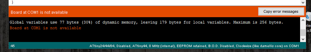
I checked the program, the number of the pins and the settings, and everything seemed to be ok. I checked the soldering and everything seems to be ok too. I used the multimeter and I had good continuity. So, why couldn't I read the information from my sensor? Maybe is the sensor broken? Maybe is a problem with the Arduino version that for some reason is not able to read the información from the sensor? After a couple of hours trying to find the mistake, I told with my instructor and following together the steps that I had followed she realized that I was connecting the FTDI to an external supply, instead of to my computer... So the computer wasn't receiving any information...
In the previous weeks, I had connected the computer to the FabISP, the FabISP to the board, and the board to an external supply. So I had that reference in my mind. But this time I didn't realize that I needed to get información directly from the board, and if I don't connect the board to the computer through the FTDI cord... #cosasdenovatos
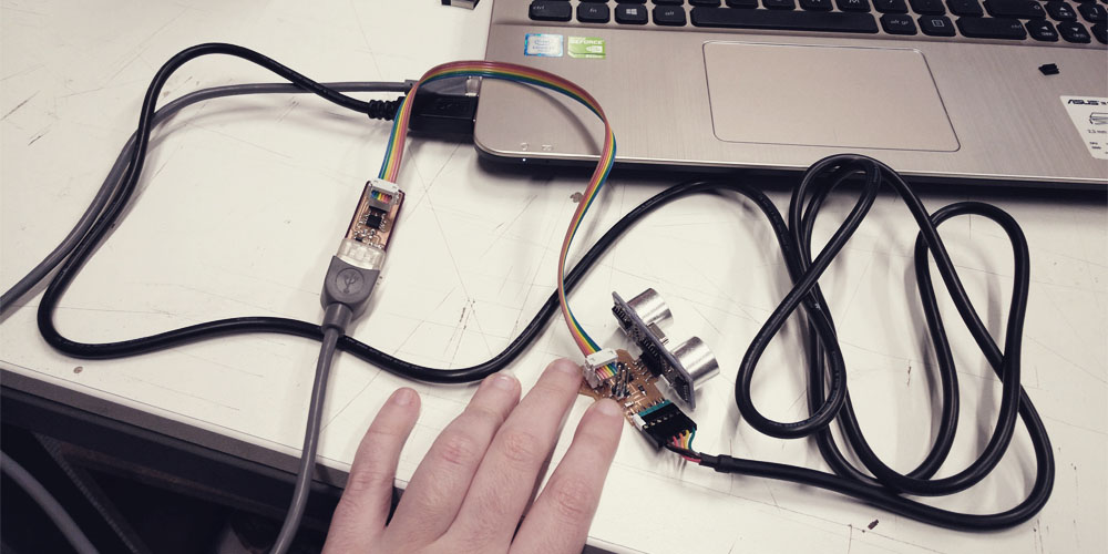
So I connected everything in the right position (computer > FabISP > board > computer) and I started getting feedback from the sensor through the serial monitor!!
I was testing the sensor and I could observe several things:
1.- In the data sheet, you can read that the range of the sensor is between 2cm. and 400cm. However, the maximum that the sensor can read is around 200cm.
2.- If for some reason the sensor gets crazy because the surface that you are using as a limit for the reading is too close or too far, I have observed that there is a point around 20-40cm that makes it come back. So probably that is the optimal distance.
3.- To get a good reading, the sensor has to be as perpendicular as possible to the reading surface (the limit for reading), otherwise, if the angle is different the pulse cannot come back and the reading will be wrong or the sensor will not work at all. For instance, I have tried to use my hand as a limit and it didn't work.
For sure I can apply this sensor to my final project, what I am a bit worried about is what I can use for the reading limit, I mean, I need to come up with some method for not getting wrong readings... maybe I may cover the sensor with something while you want to use the lamp, in such a way that if the sensor is reading 10-12cm, then the lamp turns on, but if it is reading a different number, then the lamp turn off... I think something like that could work...
Light input device: IR phototransistor
For this assignment, I also wanted to try a sensor that would be able to read the amount of light, a sensor that I could also apply for my final project. I decided to try with an IR phototransistor which I may configure for the future weeks in such a way that the lamp projects light when the room if not illuminated enough.
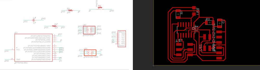
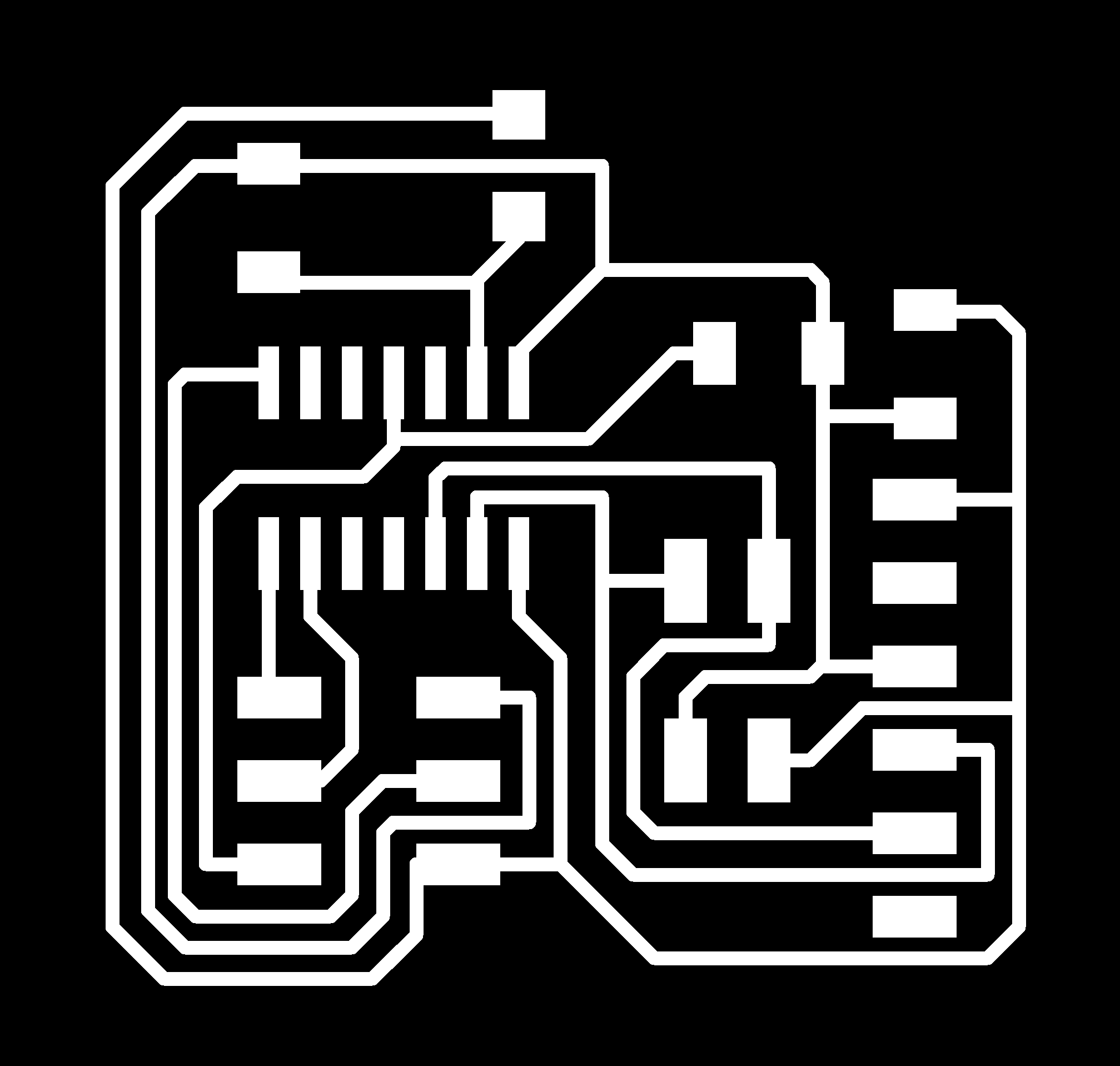
I designed the PCB in Eagle. I created a new schematic, I added all the components and I made all the connections. As in the ultrasonic sensor board, I also added a BUS connector so I can use this board for the networking and communications week. The components that I used for this boards are:
> 1 x ATtiny44
> 2 x 10kΩ resistors
> 1 x 1uF capacitor
> 1 x 2x3 pin header (ISP)
> 1 x 2x2 pin header (BUS)
> 6 x Male headers (FTDI)
> 1 x IR phototransistor
But when I checked that everything is correct, from tools > errors, a couple of warnings messages appeared, telling me that something was wrong connected. I checked the schematic and everything seemed to be good. Then I asked my instructor and she recommended me to use labels instead of lines to make the connections as sometimes Eagle gets crazy due to the overlapped lines. So I opened a new file, I imported again the components and I used the labels to make de connections. And when I went to check the errors again, it was even worse!! Now instead of having only two warning errors, I had fourteen!!
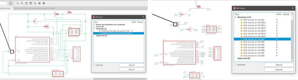
I didn't know which was the problem, the software was telling me that something was disconnected, but if I moved the component I moved de lines too, so it dindn't make any sense. I even closed and opened Eagle and I restarted the computer, but the warnings were still there... So I decided to go ahead, as in the board window everything seemed to be well connected.
PD: When I opened the Eagle file the day after, all the warning messages had disappeared. Boom! Magic! Definitely, it weren't my poor skills in Eagle, it was some bug in the schematic... Aggg I really hate this kind of things because it makes you waste a lot of time!!!
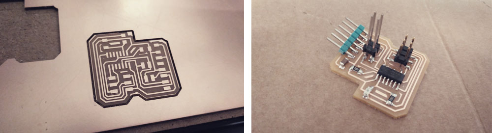
Some boards look like torture machines with so much skewer coming out from everywhere ...
Once everything was soldered I made a program in Arduino IDE. Here I had to go to the datasheet of ATtiny44A in order to know the clock that it uses, which is 8MHz. Then I had to convert de physically pins so Arduino could recognize in which pins I connected the sensor. For the serial output part, I used the SoftwareSerial Library, which is the way that you have in Arduino to get the information from other devices.
Here I had a couple of problems:
First of all, I completely forgot to connect the IR phototransistor sensor to a PWD/ADC pin, so the first time that I run the program it gave me wrong readings. So I had to do a bridge with an external cord.
And secondly, I don't know why but the readings that I was getting were upside down, I mean, I got 1024 when the room was in darkness and 0 when it was fully illuminated. To solve this, in the code I added a map funcion to invert the numbers.

I will also use this sensor in my final project. Using/applying these two sensors for the lamp I have interaction with the environment through the IR sensor (which will turn on the light when the room is not enough illuminated) and interaction with the user/person through the ultrasonic sensor (which will be able to read the presence of the person and illuminated that area of the room where he/she is).
Some weeks later I made the final version of the phototransistor's PCB. You can find more information in Final project. First prototype.
Distance input device: SHARP GP2Y0A02YK0F IR Sensor
I am adding this part of the assignment in the week 17 while developing the first prototype of the final project.
As the ultrasonic sensor has so many inconveniences in order to work well, I wanted also to tray an infrared distance sensor. To control de device I used the FabKit that I made for the first prototype of the final project.
After a couple of hours trying to get good readings from the sensor without success, I found out this tutorial and I followed it to program the microcontroller. It uses a library that reduces the lines of code and makes so much easier to use/program the sensor.
To know the pinout of my Atmega328, I used this image.
The sensor works pretty well, it is very precise in distance between 20 and 70 cm. If you place something in a distance less than 15-18 cm, the sensor gives you weird readings. From 70 cm. the readings have a mismatch of about 2 or 3 cm with respect to the actual measurement (which I think is expected and admissible, at least in my case). From 90-100 cm. the readings are not very good, you can have a mismatch of about 10 or 15 cm. and this mismatch grows exponentially as you move the reading surface away from the sensor. Although the specifications of the sensor say that it is able to work until 150 cm., from 120 cm. it doesn't work at all.
These readings can be affected by the amount of light in the room or if the reading surface is a very dark color.
In the video is a bit hard to see the values in the serial monitor (sorry for that), but the sensor is quite precise and definitely, this sensor works better for me, as I can read objects that have irregular shapes, such as a hand, or a person sited in front of the lamp... something that I cannot do with the ultrasonic one. So I will incorporate this sensor to my final project.
Files
Find below the files that I made for this assignment. Please do not hesitate to download it!! I hope you enjoy it!!
Ultrasonic sensor - traces - .png
Ultrasonic sensor - outline - .png
Ultrasonic sensor - Eagle schematic + board
Ultrasonic sensor - Arduino - .ino
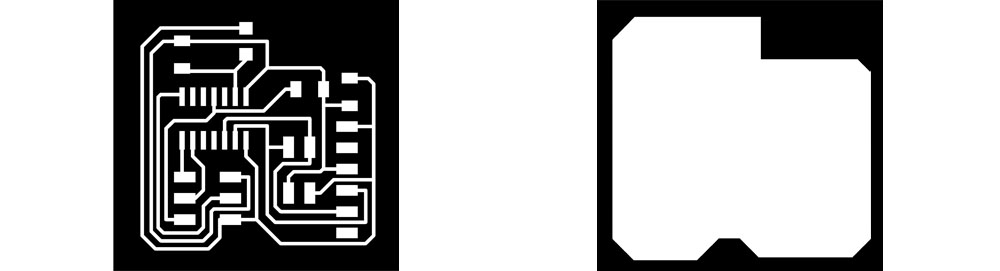
IR phototransistor - traces - .png
IR phototransistor - outline - .png
IR phototransistor - Eagle schematic + board
IR phototransistor - Arduino - .ino
SHARP GP2Y0A02YK0F IR Sensor - Arduino - .ino