18. Mechanical Design and Machine Design
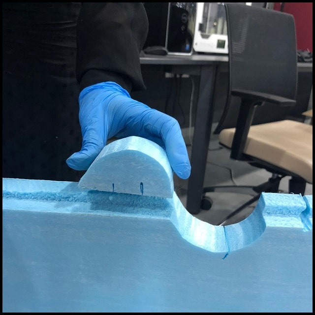
In this part we will build Arduino CNC Foam Cutting Machine. The machine is inspired by the work found here.
This is a team working task and different students will be working on different parts. My part with my colleague Hani is to work on electronics and software, including drivers, boards, motors, hot wire and control programs.
At the beginning we had a team discussion and assigned tasks to sub groups, and we worked in parallel on all machine parts (mechanical, electronics, 3D printing and software). We had three sub groups:
Aziz, Hani: Electronics and software.
Faisal, Hani: Mechanical design.
Batoul, Omar: 3D printing.
When all assigned tasks completed, we all worked as a group to assemble and test the machine, including axes movement, axes calibration, and hot wire calibration. Then we made cutting tests and captured one in the Hero Shoot video.
Group Page
Individual Contribution
File Download
DRV8825 driver module datasheet
GRBL firmware
Universal G-code Sender
Arduino CNC Machine Electronics
Electronics BOM
| Item | Qty. | Source |
|---|---|---|
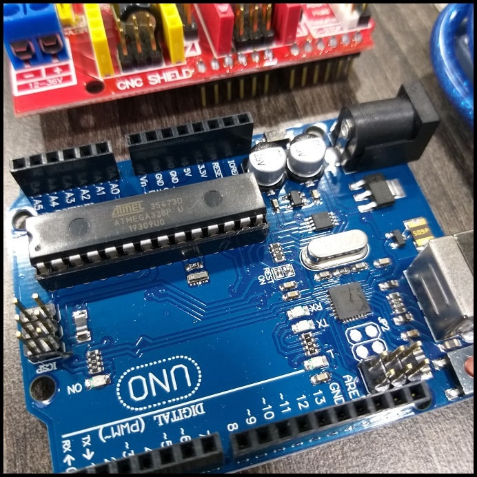
| ARDUINO UNO - R3 | 1 pcs. | Local market |
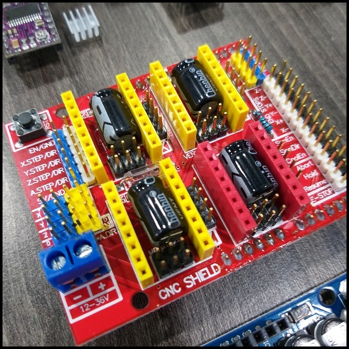
| ARDUINO CNC SHIELD V3 | 1 pcs. | Local market |
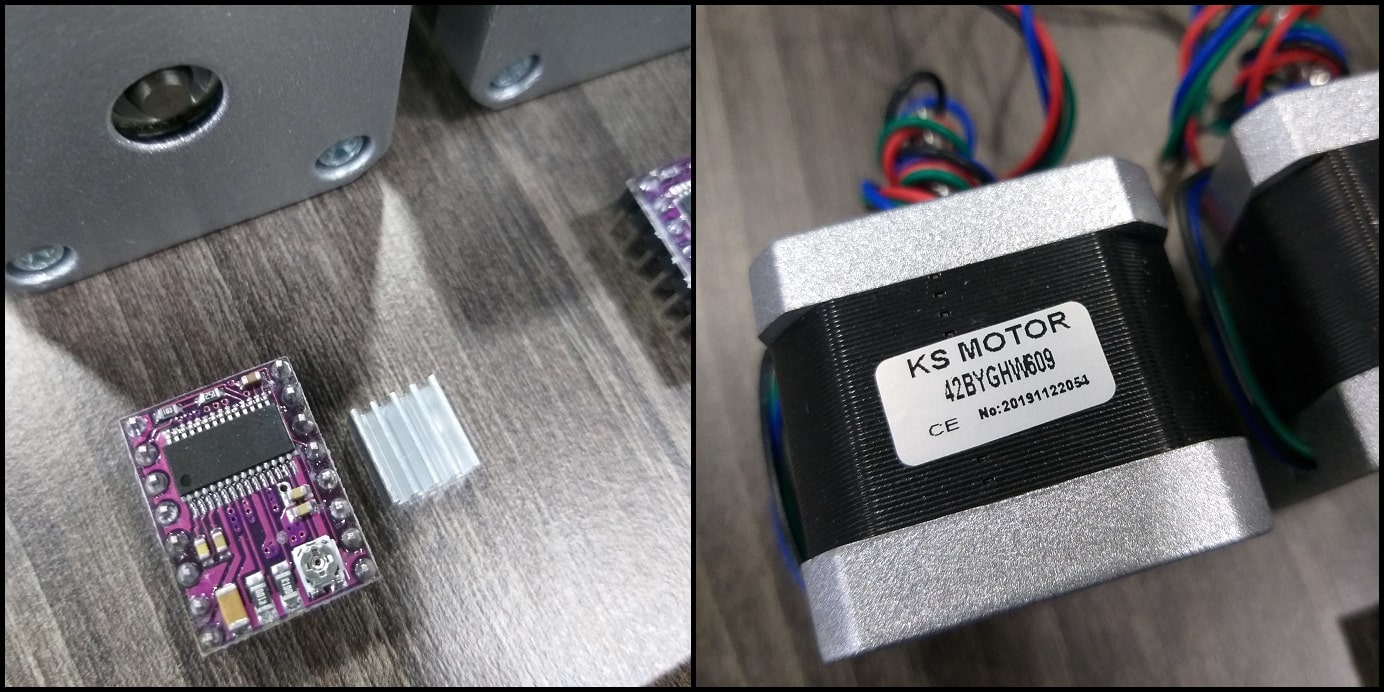
| DRV8825 STEPPER MOTOR DRIVER MODULE | 4 pcs. | Local market |
| STEPPER MOTOR 1.8° PER STEP, 1.7 A, 0.36 N.M (NEMA17) | 3 pcs. | Local market |
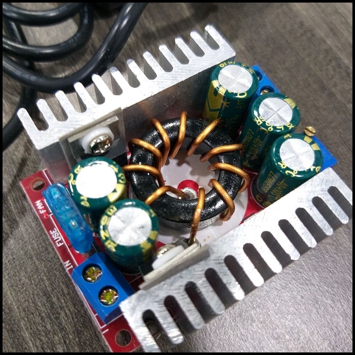
| DC-DC STEP DOWN15A CONVERTER 4-32V 12V TO 1.2-32V BUCK ADJUSTABLE | 1 pcs. | Local market |
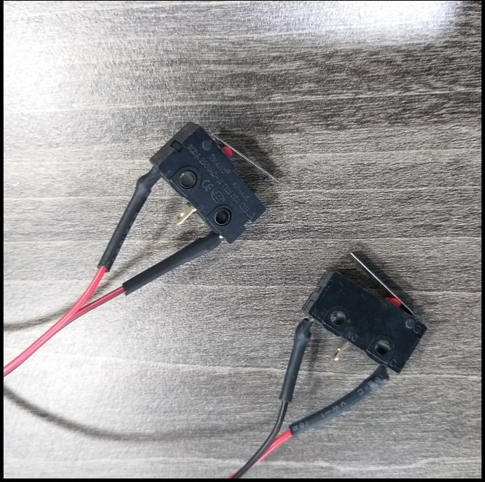
| MICRO NORMALLY OPEN CLOSE LIMIT SWITCH | 2 pcs. | Local market |
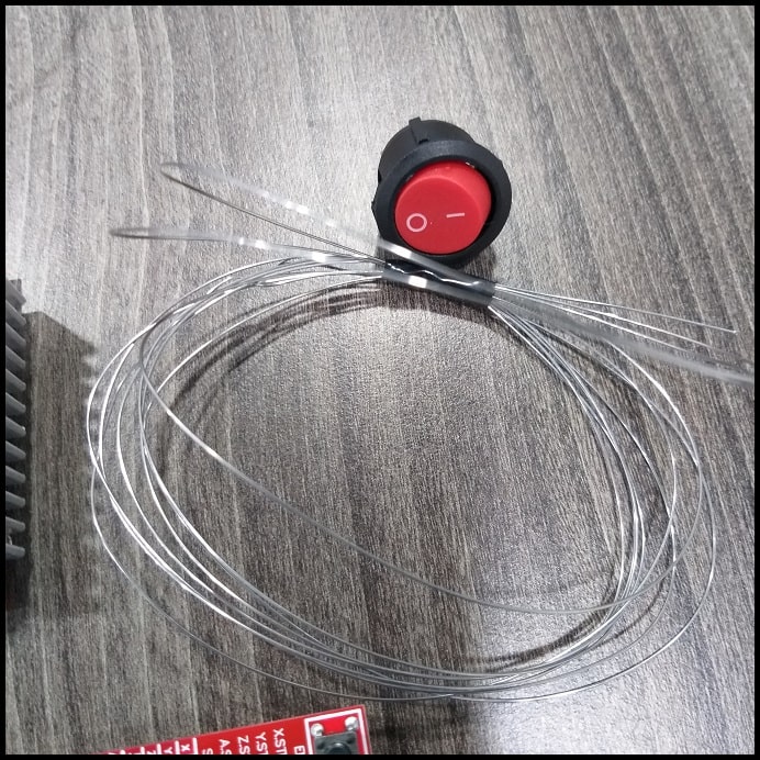
| Hot wire | 2 m | Local hardware store |
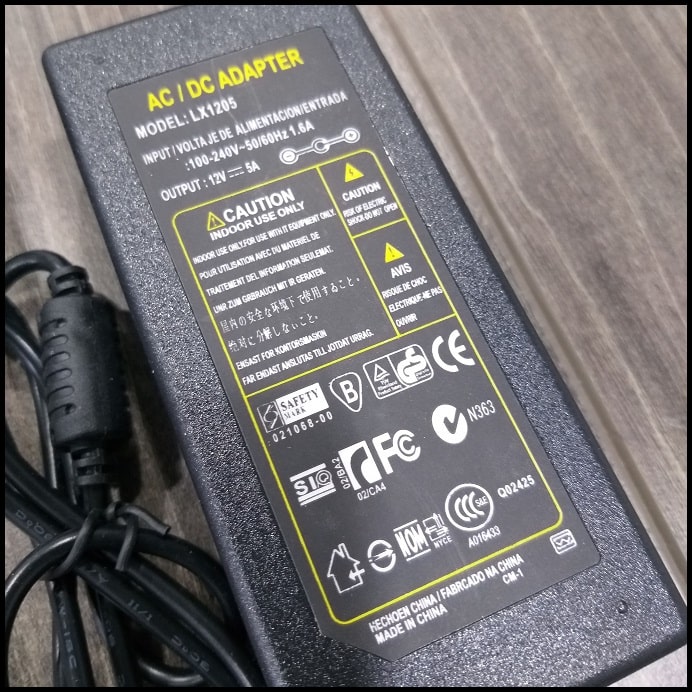
| ADAPTER 12V 5A POWER SUPPLY AC/DC | 1 pcs. | Local market |
The Arduino Uno is where the GRBL will be installed and will control the machine.
DRV8825 drivers will control the steppers which provide motion.
Arduino CNC shield interfaces DRV8825 drivers to Arduino board.
DC-DC converter will control the temperature of the hot wire
Limit switches will define the zero or home position of +X and +Y axes.
Hot wire will heat cut the foam. Hot wire should maintain uniform temperature along its length when it heats up.
And finally, the adaptor will supply power to the whole system.
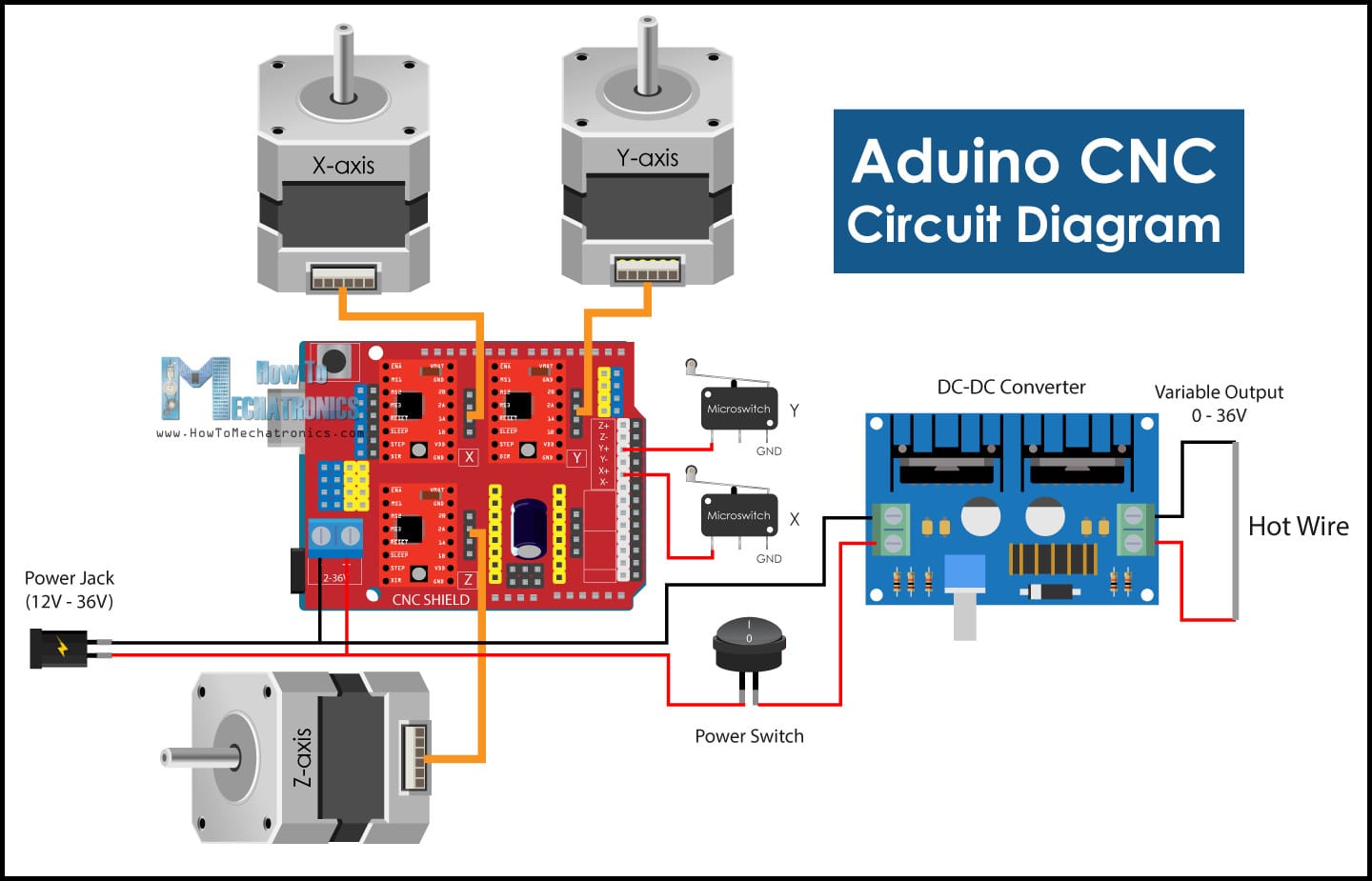
Circuit Diagram
The image below shows how different components are connected to each other. Note how all components are interfaced to Arduino board using the CNC shield. This will make connected compact and easier to complete.
Driver Resolution
The DRV8825 driver can be set to drive stepper motors at different resolutions. The driver resolution selectors have 100 kOhm pull-down resistors, which makes them level LOW if there are left unconnected.
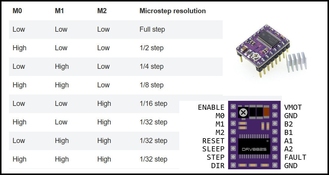
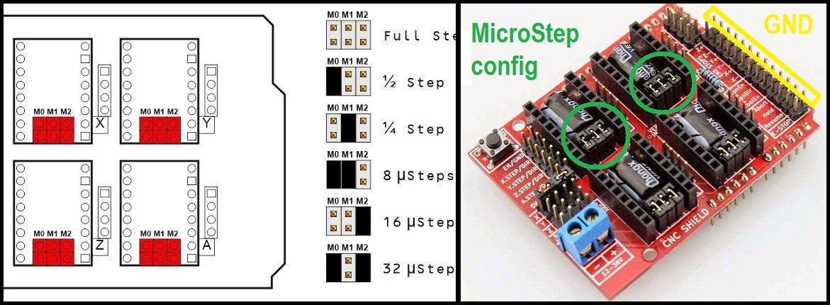
The CNC shield has connections to resolution selectors and jumpers can be used to set the required resolution. A connected jumper will drive the selector pin (M0, M1, M2) to level high. The image below shows some examples for driver resolution for DRV8825. In our machine will use 1/16 stepper resolution.
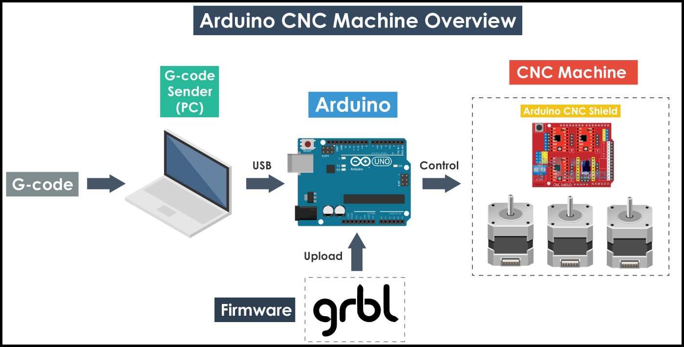
Arduino CNC machine Software
Two programs will be used to control the machine. The first is GRBL firmware which will installed into Arduino board and enable it to understand g-codes, and the other is g-code sender that will be installed to PC and communicate with Arduino board and send g-codes.
GRBL Firmware
GRBL is a firmware for Arduino board running on ATmega328P microprocessor. GRBL accepts g-code as inputs and generates outputs at Arduino board pins. Compared to industrial CNC machines, when GRBL is used there is no need for any ports to control the machine, only the USB port connected to Arduino board. In other words, when GRBL firmware is installed to Arduino board, it will read g-codes and control the machine accordingly. To know more about GRBL, check the project page.
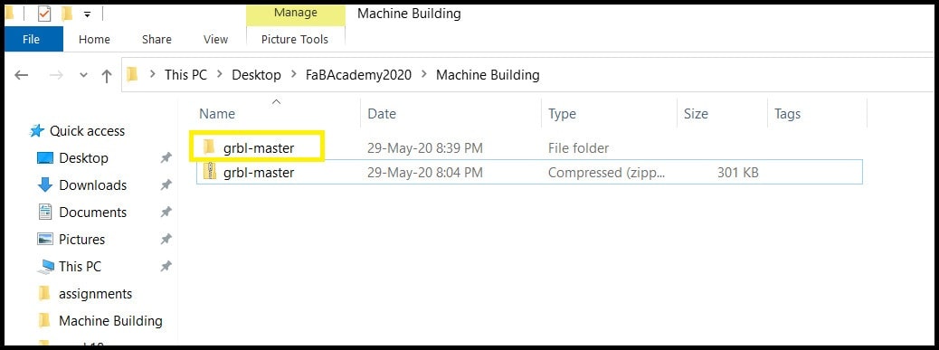
Step 1: Download GRBL firmware and extract it and copy the folder “grbl-master”. Do not copy this folder to “Arduino library directory!”
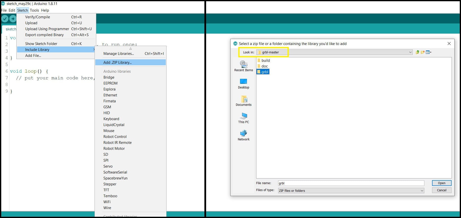
Step 2: In Arduino IDE go to “Sketch > Include Library > Add .ZIP Library…” and from inside “grbl-master” folder locate “grbl” folder. Click open.
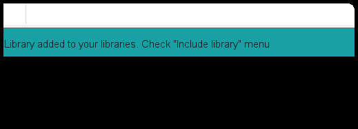
You should receive the message below.
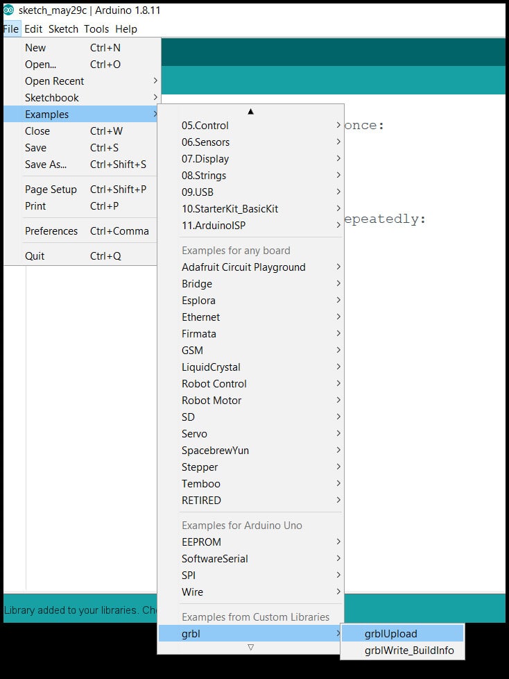
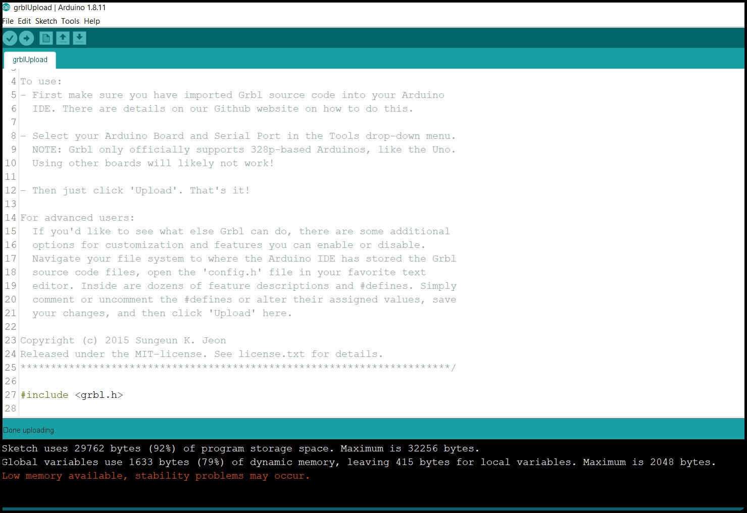
Step 3: Go to “File > Examples > grbl > grblUpload”, select the Arduino board (UNO in our case) and the COM port, click upload.
Note that the firmware used most of the board memory.
Step 4: Open the “Serial Monitor” and set baud rate to 115200. You should see “Grbl 1.1h [‘$’ for help] ” in serial monitor. Type “$$” and send, settings list will appear. We will modify these settings to fit with our machine using the GRBL controller software or g-code sender.
Step 5: Since we don’t have a Z-axis switch, we should define that in the config.h file of GRBL. Go to “Arduino library directory > grbl” and open config.h, then find the following parts
// NOTE: Defaults are set for a traditional 3-axis CNC machine. Z-axis first to clear, followed by X & Y.
#define HOMING_CYCLE_0 (1<<Z_AXIS)                // REQUIRED: First move Z to clear workspace.
#define HOMING_CYCLE_1 ((1<<X_AXIS)|(1<<Y_AXIS))  // OPTIONAL: Then move X,Y at the same time.
// #define HOMING_CYCLE_2                         // OPTIONAL: Uncomment and add axes mask to enable

// NOTE: The following are two examples to setup homing for 2-axis machines.
// #define HOMING_CYCLE_0 ((1<<X_AXIS)|(1<<Y_AXIS))  // NOT COMPATIBLE WITH COREXY: Homes both X-Y in one cycle.

// #define HOMING_CYCLE_0 (1<<X_AXIS)  // COREXY COMPATIBLE: First home X
// #define HOMING_CYCLE_1 (1<<Y_AXIS)  // COREXY COMPATIBLE: Then home Y
and change it to
// NOTE: Defaults are set for a traditional 3-axis CNC machine. Z-axis first to clear, followed by X & Y.
//#define HOMING_CYCLE_0 (1<<Z_AXIS)                // REQUIRED: First move Z to clear workspace.
//#define HOMING_CYCLE_1 ((1<<X_AXIS)|(1<<Y_AXIS))  // OPTIONAL: Then move X,Y at the same time.
// #define HOMING_CYCLE_2                         // OPTIONAL: Uncomment and add axes mask to enable

// NOTE: The following are two examples to setup homing for 2-axis machines.
// #define HOMING_CYCLE_0 ((1<<X_AXIS)|(1<<Y_AXIS))  // NOT COMPATIBLE WITH COREXY: Homes both X-Y in one cycle.

#define HOMING_CYCLE_0 (1<<X_AXIS)  // COREXY COMPATIBLE: First home X
#define HOMING_CYCLE_1 (1<<Y_AXIS)  // COREXY COMPATIBLE: Then home Y
Save the file and reupload the “grblUpload” sketch to our Arduino board.
GRBL Controller Software (g-code Sender)
This software will generate g-codes according to job and send those codes to Arduino board (which knows how to read g-codes now!). We will use Universal G-code Sender.
Step 1: Install JAVA Runtime Environment to your PC from here. The GRBL controller is a JAVA program and runtime environment should be installed. You may need to create an account.
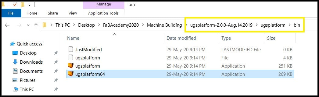
Step 2: Go to download page and download 2.0 Platform version and extract the zip file. Inside extracted file open “ugsplatfrom > bin” and run one of the executable files (ugsplatform64 in my case).
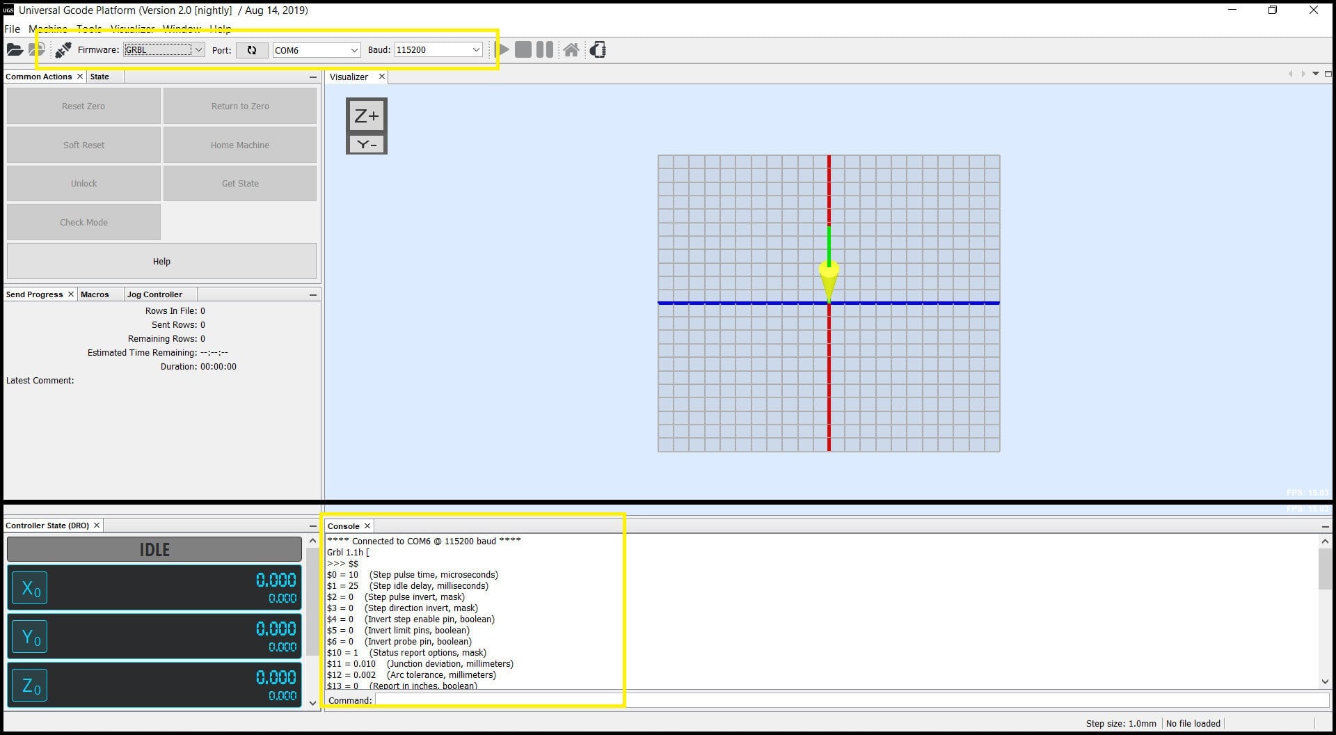
Step 3: Connect to Arduino board. Set baud rate to 115200 and the right COM port. Click on “Connect/Disconnect” button. In the console window you should see connection confirmation and defined settings.
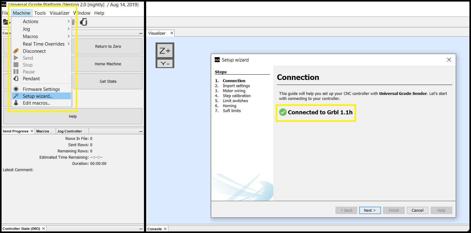
Step 4: To configure the machine, we will use the built in setup wizard. Go to “Machine > Setup wizard…”. A new window will appear, which will confirm connection to GRBL.
Testing System Component
Steppers and Limit Switches
We tested system components before assembly to the mechanical part of the machine.
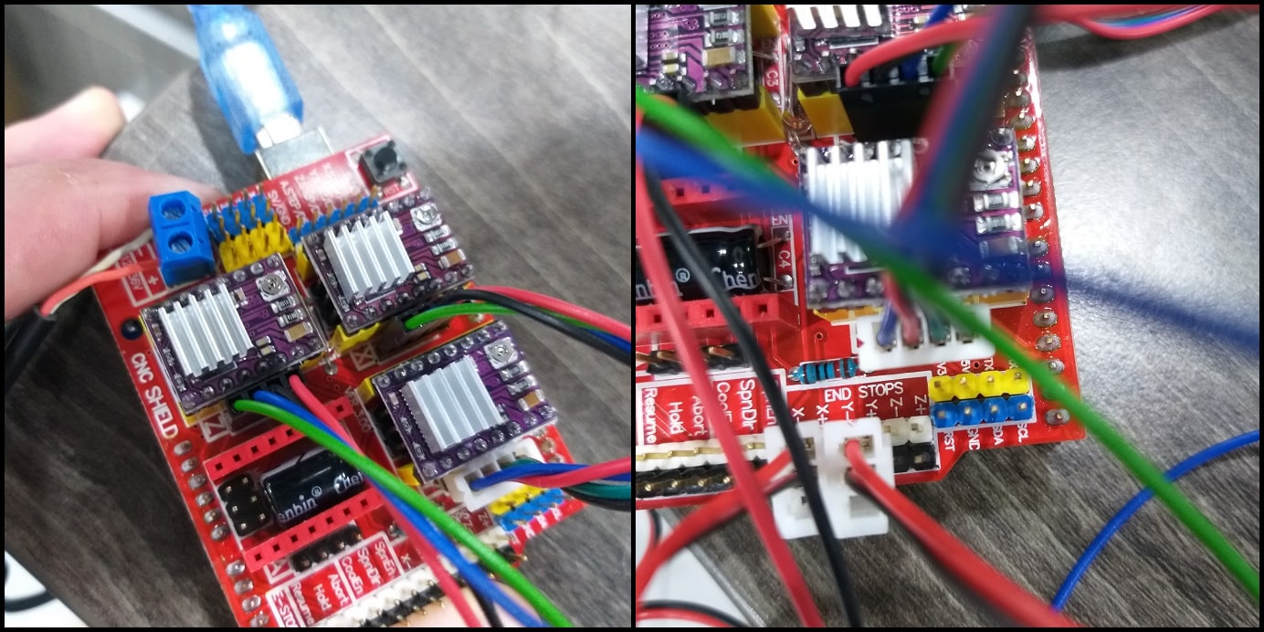
First we connected the CNC shield to Arduino board and put a jumper to M2 pins for each axis (1/16 resolution), then connected the DRV8825 stepper driver.
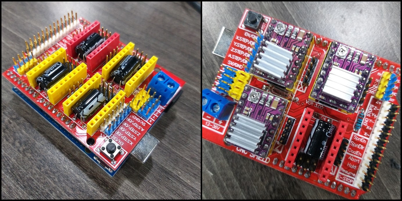
Then we connected stepper motors, limit switches for +X and +Y axes, powered the shield with +12 VDC and connected Arduino USB cable.
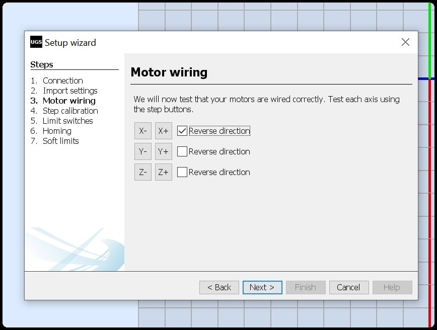
To test steppers and limit switches, we used the g-code sender. We ran the setup wizard and connected to GRBL in Arduino. In “Motor wiring”, we tested the operation for each stepper and tried to reverse direction.
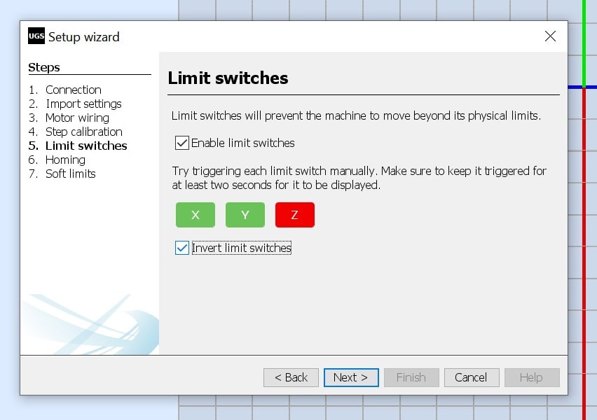
And we used the “Limit switches” section to test +X and +Y home switches. First limit switches were enabled. Note that the Z axis is rotational and has no home position. In hardware we have normally closed switches. In normal position when the switches are not actuated the switch box will be in green, and should turn into red when the switch is actuated. “Invert limit switches” checkbox is checked to achieve this.
Hot wire
First we tested the hot wire using the DC-DC stepdown converter. We tried the hot wire at different voltages. The maximum output we could achieve from the converter was 8.17 VDC, and was not enough to have a good cut.
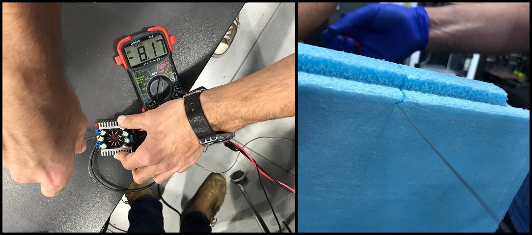
Then we connected the hot wire to +12 VDC, and removed the converter from the system and directly connected the hot wire to system power adapter. Cutting results were better and acceptable.
Hero Shoots!
This video shows steppers testing. The X-axis stepper was rotating in reverse direction compared to Y and Z axes steppers. We reversed the rotation of X-axis stepper using the g-code sender.
This video shows limit switches. When actuated, switches colors turn into red in g-code sender programs. We inverted switches since we are using NC ones.
This video shows the hot wire cutting test using +12 VDC.