6. 3D Scanning and Printing
Group Assignment
3D Printer: Ultimaker 2+
Machine: Ultimaker 2+
Slicing Software: Ultimaker Cura
File Download
Ultimaker 2+ profile settings file
Supported overhang STL file
Supported clearance STL file
Supported overhang and clearance gcode file
Unsupported angle STL file
Unsupported overhang STL file
Unsupported bridging STL file
Unsupported angle, overhang and bridging gcode file
Wall thickness STL file
Dimensions STL file
Wall thickness and dimensions gcode file
Anisotropy STL file
Surface finish STL file
Anisotropy and surface finish gcode file
Infill 0% STL file
Infill 0% gcode file
Infill 15% STL file
Infill 15% gcode file
Infill 50% STL file
Infill 50% gcode file
Infill 100% STL file
Infill 100% gcode file
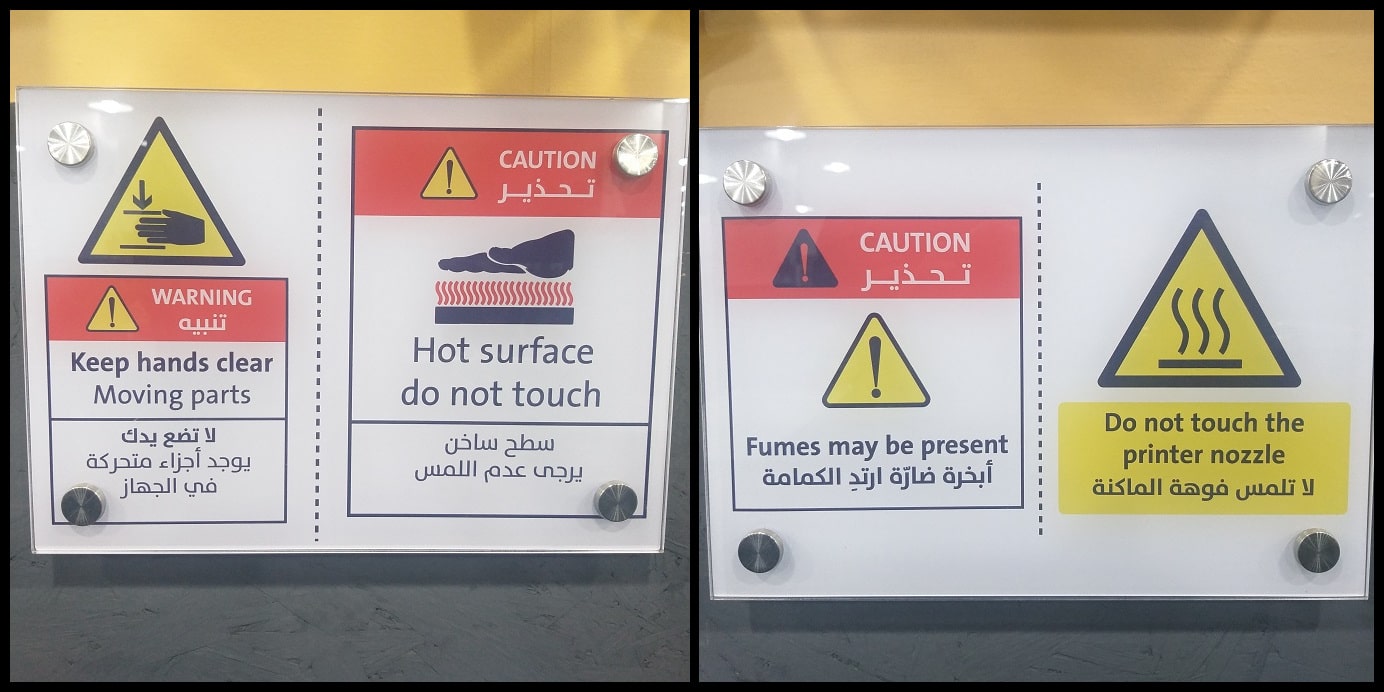
Safety First!: Safety cautions and procedures must be considered while working on 3D printers. Please read, understand and apply all caution signs.
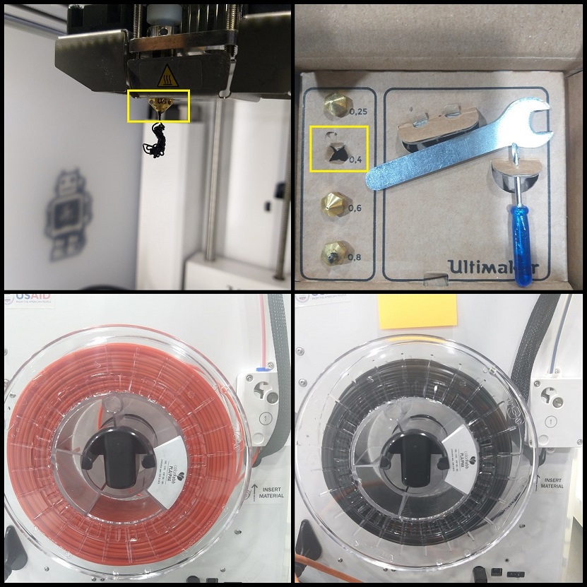
The Ultimaker 2+ is a Fused Deposition Modelling (FDM) printer which has a Cartesian work volume (X, Y, Z). It is optimized for 0.4 mm nozzle size and 2.85 mm filament. Other nozzles can be used on the printer. We are going to use 0.4 mm nozzle and 2.85 mm Polylactic Acid (PLA) filament.
Ultimaker 2+ printing limits are X x Y x Z = 223 x 223 x 205 mm. It is an open work volume printer, which means it won’t do great on ABS.
Design Rules
When you work on a model to 3D print, there are some rules and restrictions that are recommended to apply. Rules should be considered at the time of making the 3D model to have the best prints.
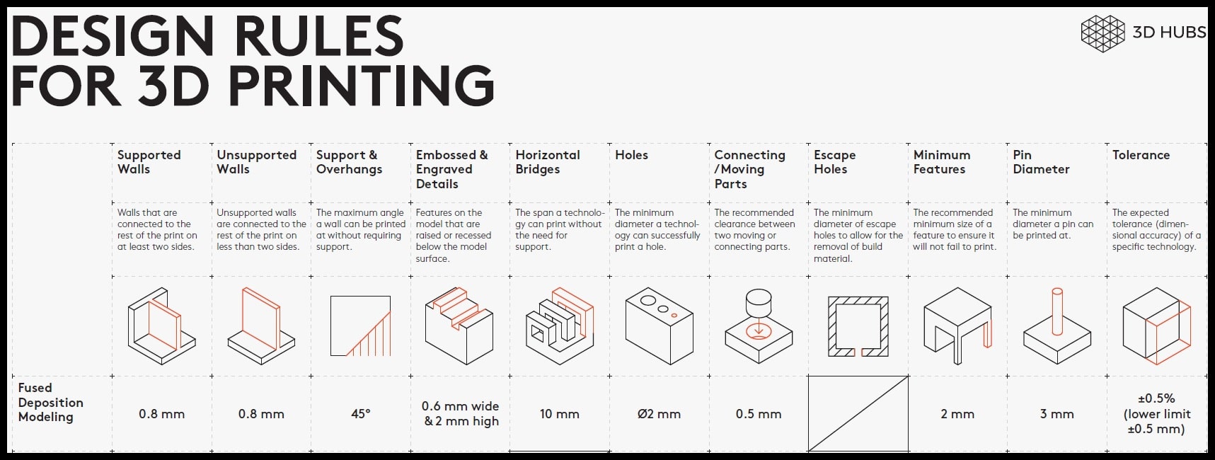
These are the design rules for FDM printing (Source). For example, when working with holes, the minimum recommended hole diameter is 2.0 mm.
We printed 13 different designs to test the design rules on our printer; the Ultimaker 2+.
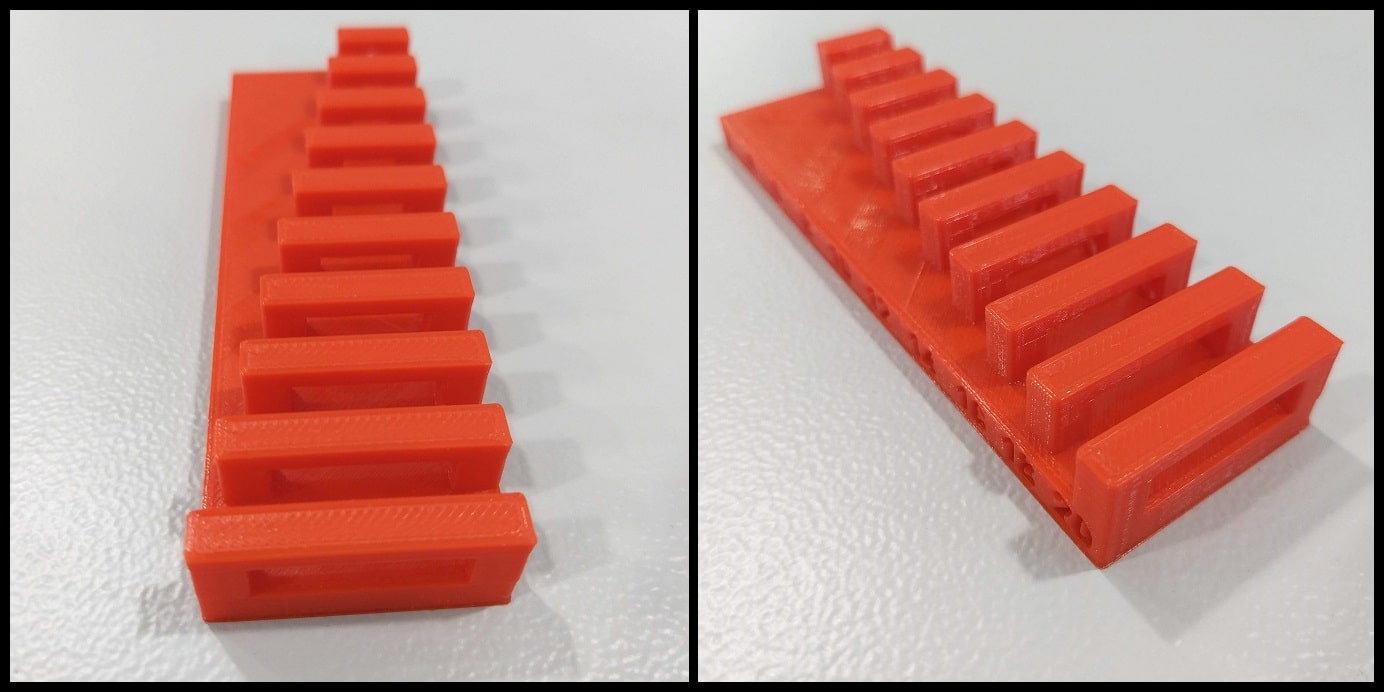
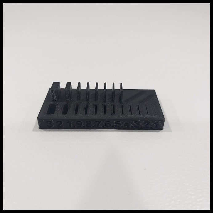
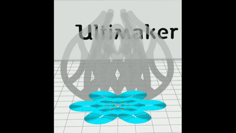
Part 1: Supported Overhangs and Clearance: This print consists of two STL files. The point is to test the quality of supported overhang and clearance between moving parts.
Step 1: Download the files “Supported overhang” and “Supported clearance” STL files. If you are using Ultimaker 2+ you can download the associated gcode files and print.
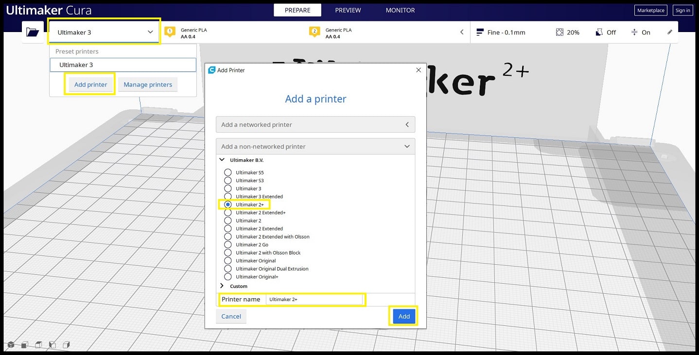
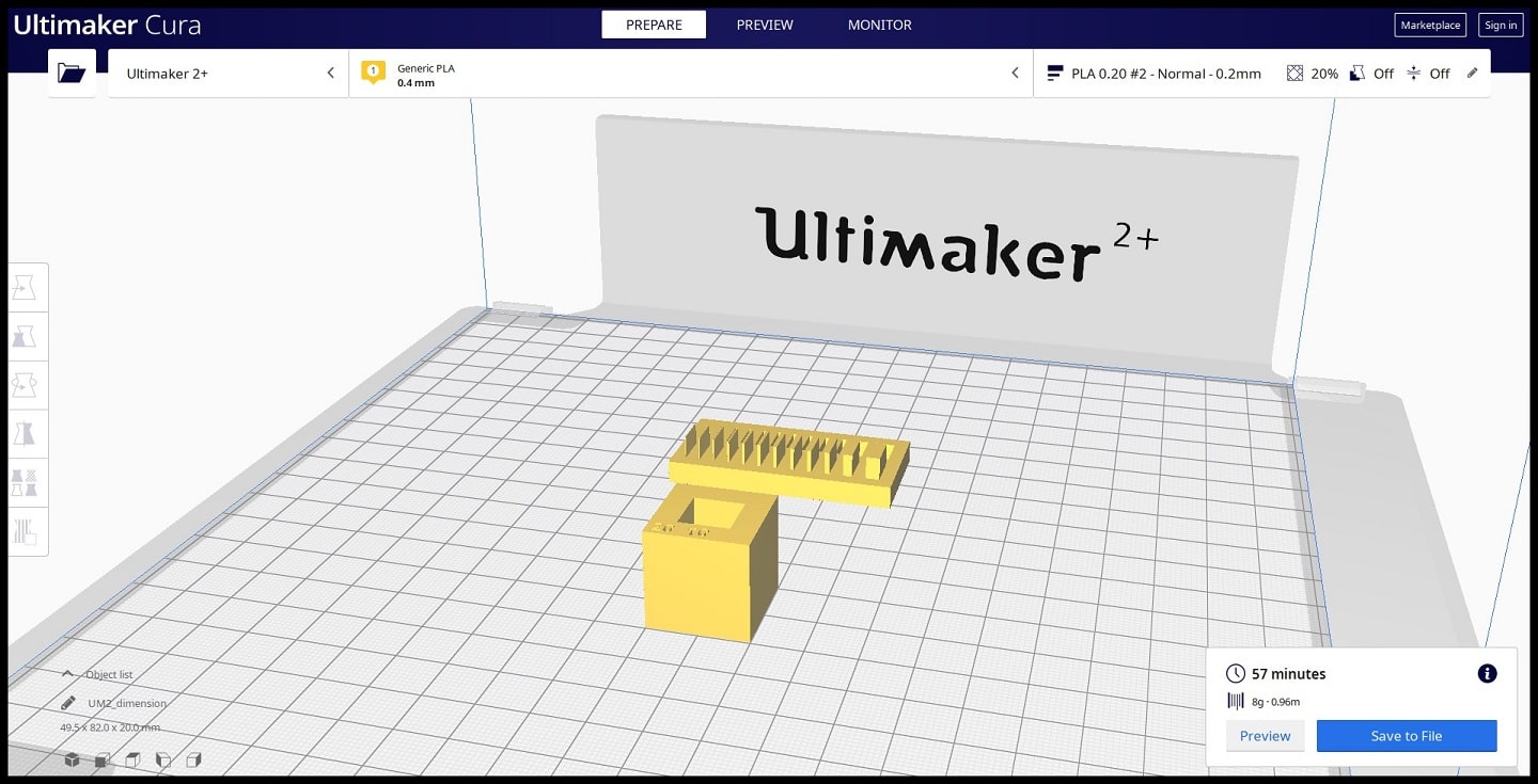
Step 2: Open Ultimaker Cura. Click on “Printers” dropdown menu and then on “Add Printer”. Select “Ultimaker 2+” from the list and then “Add”. Now the Ultimaker 2+ is added to printers list and can use it through the slicing software.
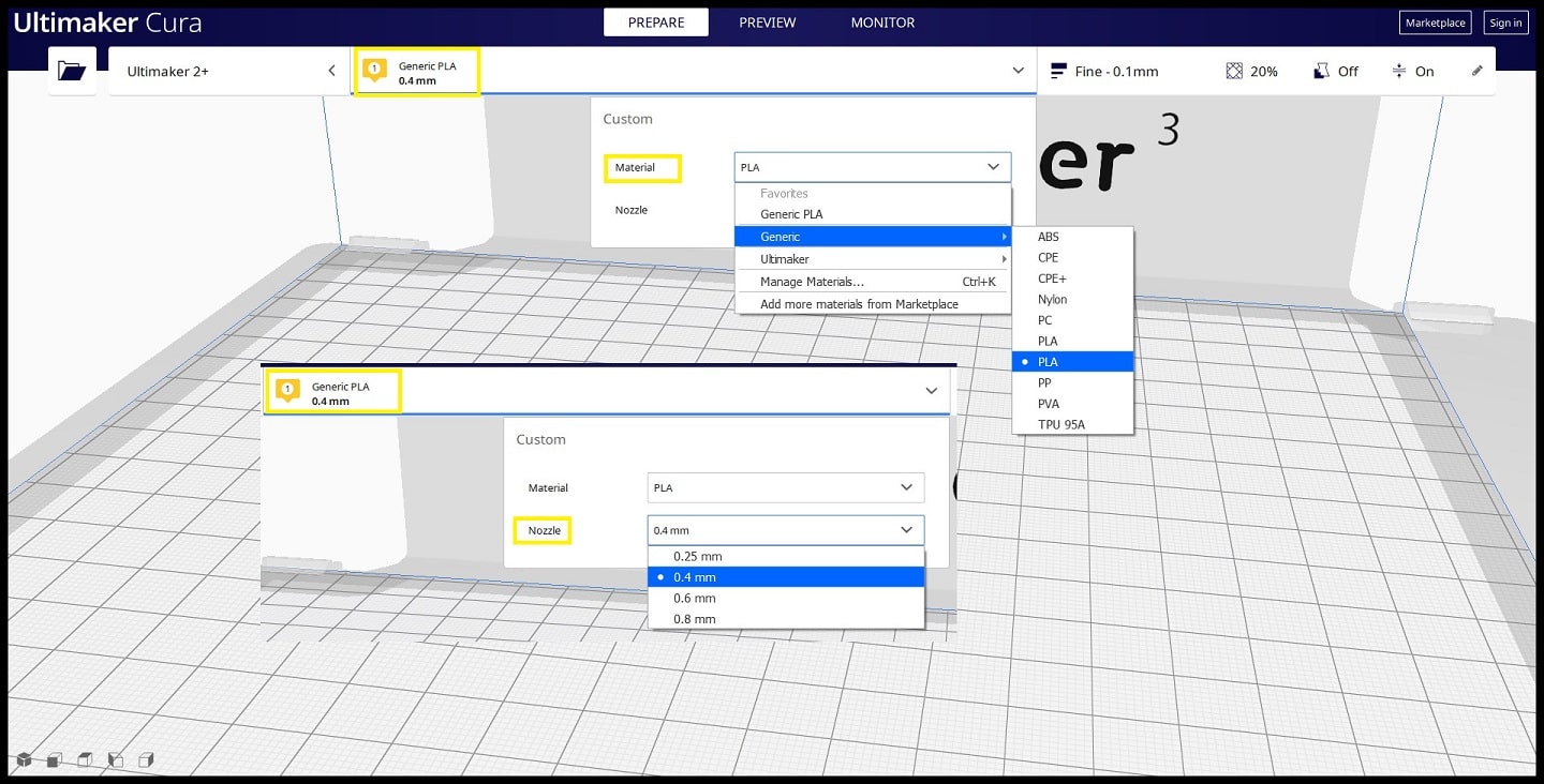
Step 3: Click on “Nozzle 1” settings and from “Material” dropdown menu select “Generic > PLA” or “Ultimaker > PLA” if you are using Ultimaker filaments. From “Nozzle” dropdown menu select 0.4 mm.
Step 4: Click on “Printing Settings” and then “Custom”. Here we can change default printing settings.
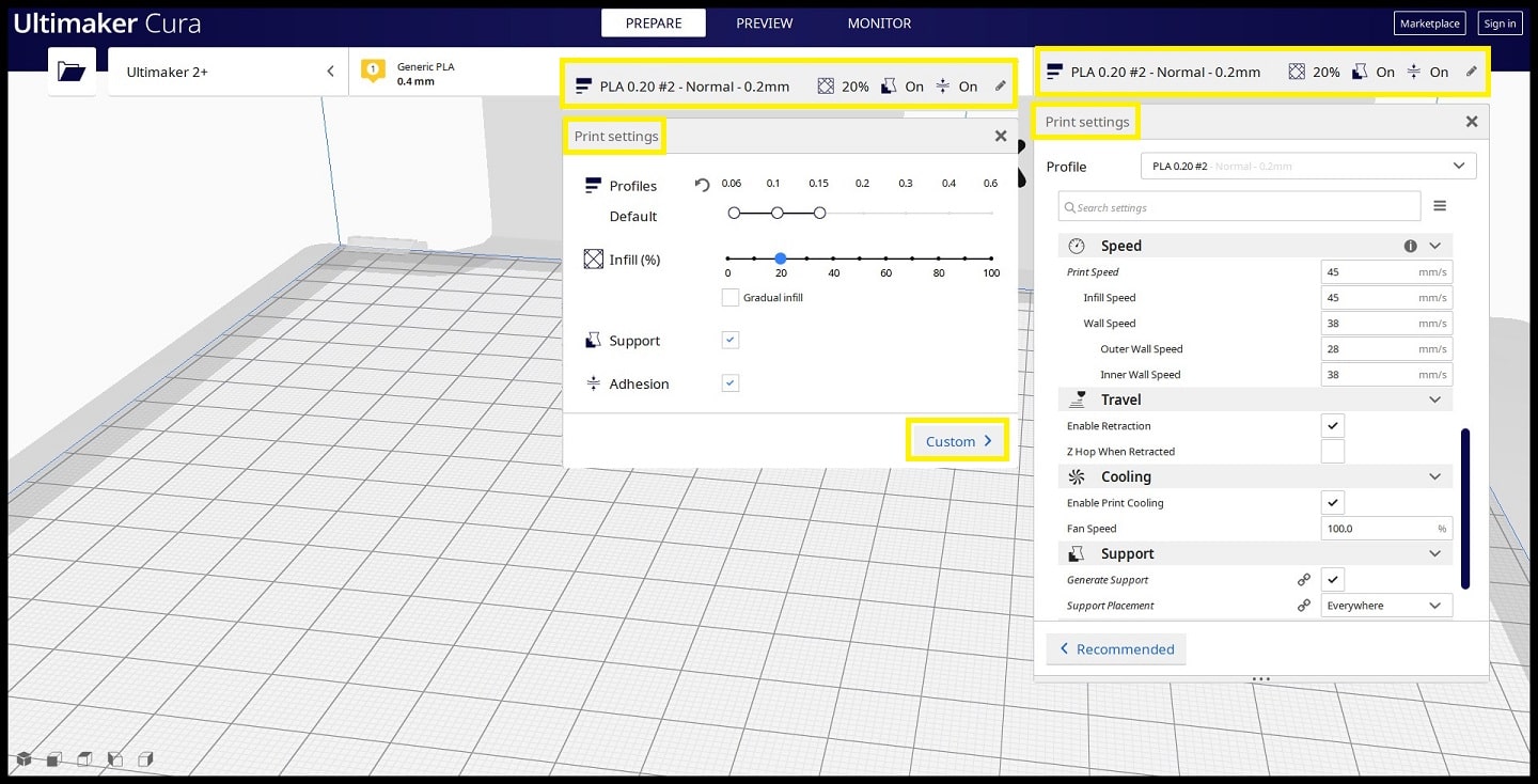
We used the settings below to print the first part of design rules test.
Quality
Layer Height: 0.20 mm
Line Width: 0.35 mmShell
Wall Thickness: 0.7 mm
Top/Bottom Thickness: 0.6 mmInfill
Infill Density: 20%
Infill Pattern: GridMaterial
Printing Temperature: 200 °C
Build Plate Temperature: 60 °CSpeed
Print Speed: 45 mm/sTravel
Enable Retraction: YesCooling
Enable Print Cooling: Yes
Fan Speed: 100%Support
Generate Support: Check
Support Placement: Everywhere
Support Overhang Angel: 50°
Support Pattern: ZigZagBuild Plate Adhesion
Build Plate Adhesion Type: Skirt
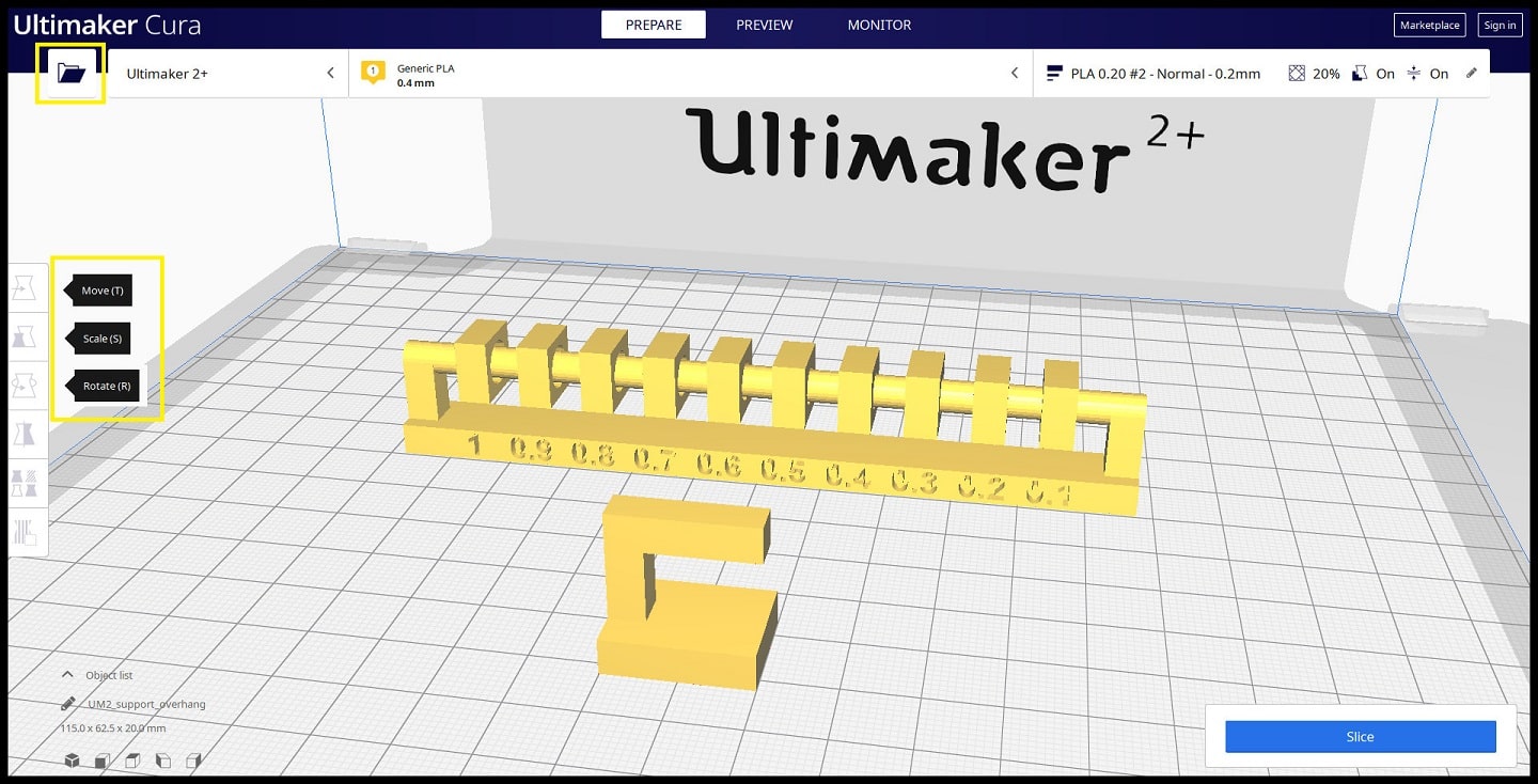
Step 5: Click on “Open File(s)” icon and select the STL file. Use “Move”, “Scale” and “Rotate” to control the position, size and orientation of your print.
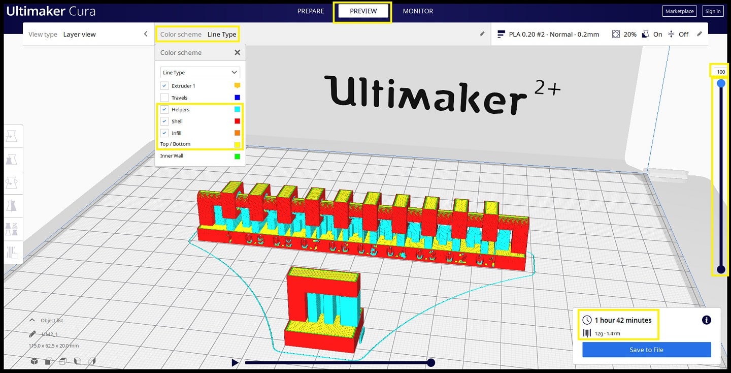
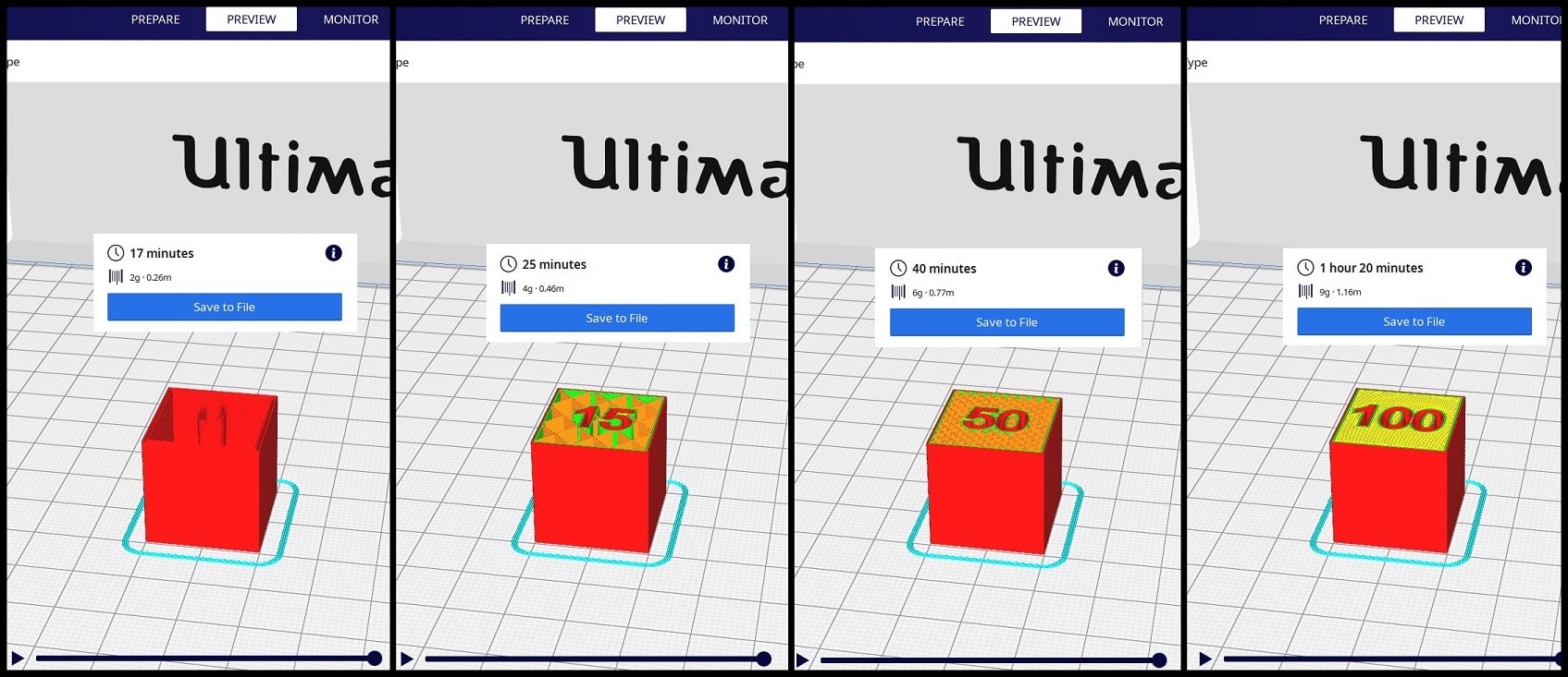
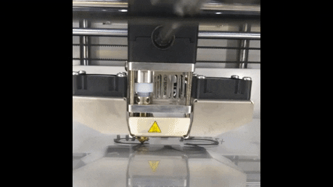
Step 6: Click on “Slice”. When slicing finishes you can see needed time to complete the print as well as quantity of material needed in grams and meters. Click on “Preview” and you can see number of layers (100), support and skirt (in blue), shell (in red), infill (in orange) and top/bottom layers (in yellow). Move the vertical slider bar to see layer by layer action.
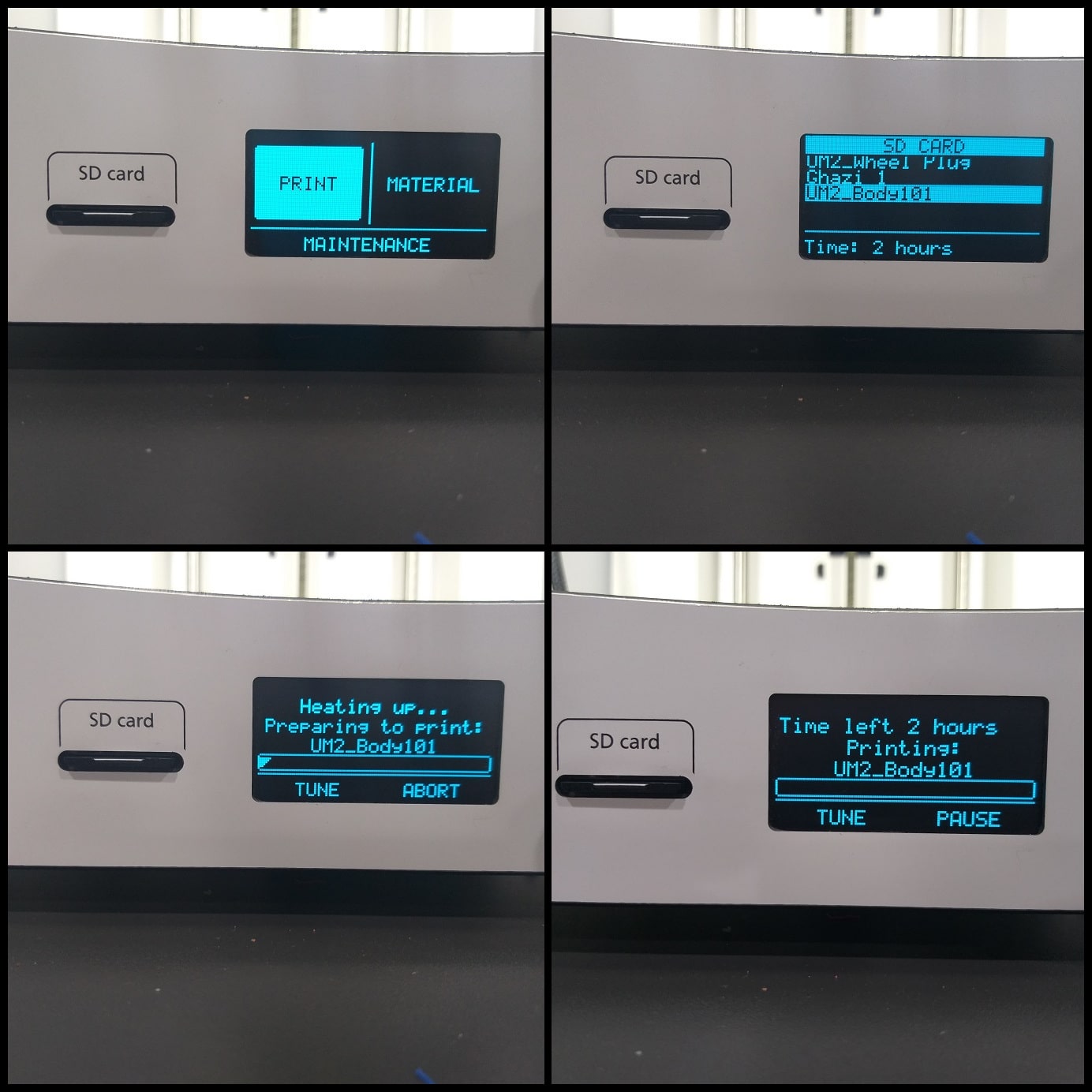
Step 7: Click on “Save to File” and save the gcode file to printer storage media. Make sure that the correct material (PLA 2.85 mm) and nozzle (0.4 mm) are used on the printer.
Click on “Print” then find your model and press on the knob to select it and start printing. Printing will start heating up. When it is done printer will start printing and show remaining time.
Findings:
Supported overhang shows good quality after support removal.
Supported clearance shows a good clearance at 0.3 mm. Clearance less than 0.3 mm (0.1 mm and 0.2 mm) is not enough to make object move.
![]()
Part 2: Unsupported Overhangs, Bridging and Angle: This print consists of three STL files. The point is to test the quality of unsupported overhangs, bridging and angles.
Step 1: Download the files “Unsupported overhang”, “Unsupported bridging” and “Unsupported angle” STL files. If you are using Ultimaker 2+ you can download the associated gcode files and print.
Step 2: Use the following printing settings.
Quality
Layer Height: 0.20 mm
Line Width: 0.35 mmShell
Wall Thickness: 0.7 mm
Top/Bottom Thickness: 0.6 mmInfill
Infill Density: 20%
Infill Pattern: GridMaterial Printing Temperature: 200 °C
Build Plate Temperature: 60 °CSpeed
Print Speed: 45 mm/sTravel
Enable Retraction: YesCooling
Enable Print Cooling: Yes
Fan Speed: 100%Support
Generate Support: UncheckBuild Plate Adhesion
Build Plate Adhesion Type: Skirt
Step 3: Click on “Open File(s)” icon and select the STL file. Use “Move”, “Scale” and “Rotate” to control the position, size and orientation of your print.
Step 4: Repeat Step 6 and Step 7 in Part1.
Findings:
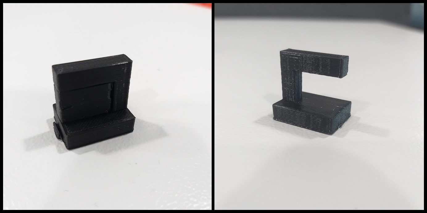
Unsupported bridging seems to work fine over all lengths.
Unsupported overhangs show bad quality from the shortest length (1 mm).
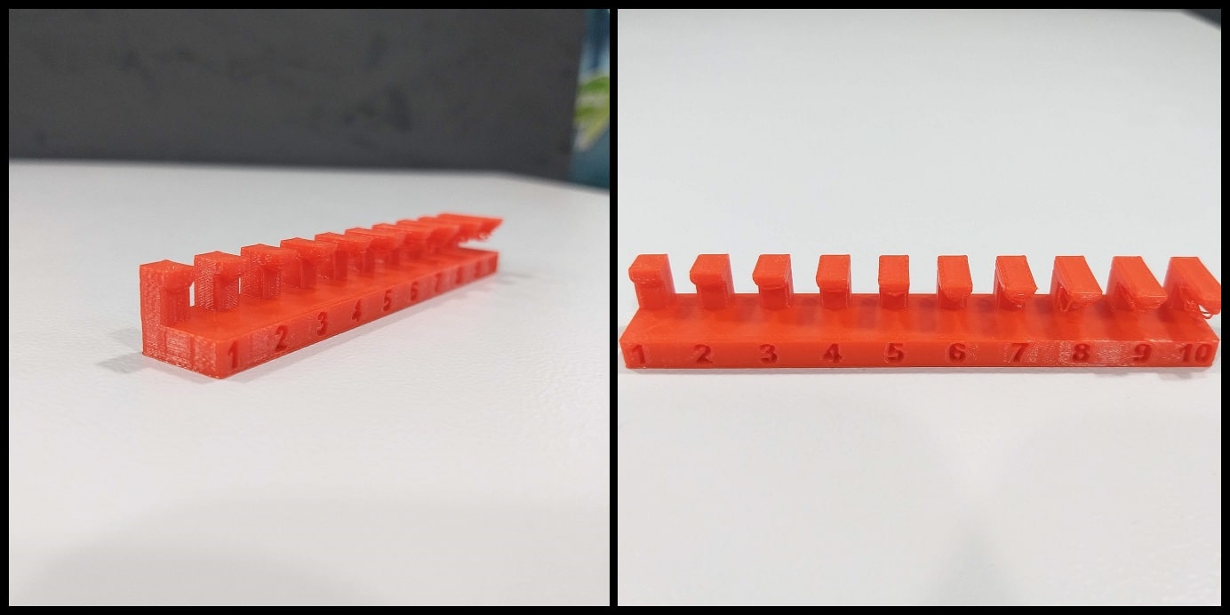
Unsupported angles show good quality at angles >= 50 Deg.
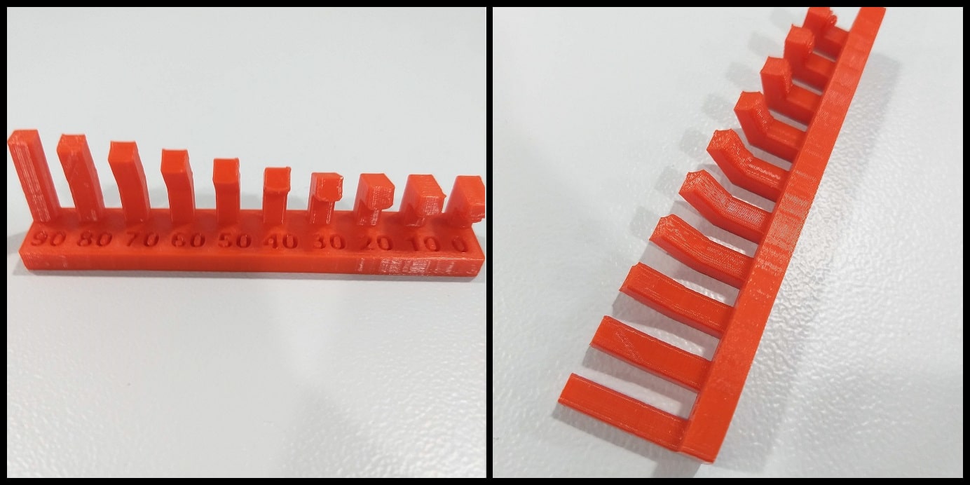
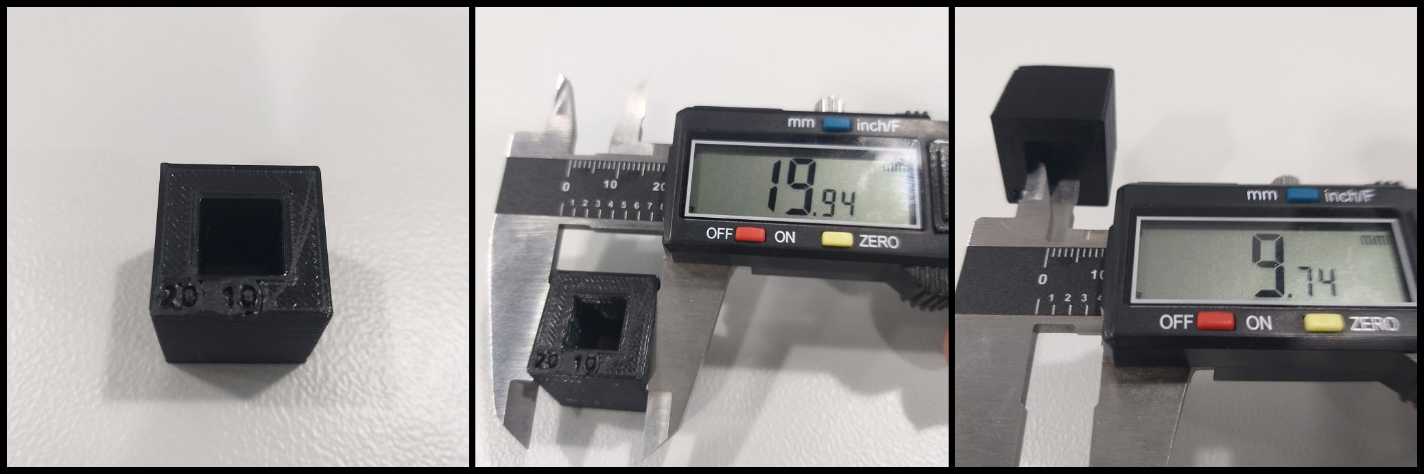
Part 3: Wall Thickness and Dimension: This print consists of two STL files. The point is to test the quality of wall thickness and dimensions.
Step 1: Download the files “Wall thickness” and “Dimensions” STL files. If you are using Ultimaker 2+ you can download the associated gcode files and print.
Step 2: Use the following printing settings.
Quality
Layer Height: 0.20 mm
Line Width: 0.35 mmShell
Wall Thickness: 0.7 mm
Top/Bottom Thickness: 0.6 mmInfill
Infill Density: 20%
Infill Pattern: GridMaterial Printing Temperature: 200 °C
Build Plate Temperature: 60 °CSpeed
Print Speed: 45 mm/sTravel
Enable Retraction: YesCooling
Enable Print Cooling: Yes
Fan Speed: 100%Support
Generate Support: UncheckBuild Plate Adhesion
Build Plate Adhesion Type: Skirt
Step 3: Click on “Open File(s)” icon and select the STL file. Use “Move”, “Scale” and “Rotate” to control the position, size and orientation of your print.
Step 4: Repeat Step 6 and Step 7 in Part1.
Findings:
Wall thickness less than 0.5 mm were not printed. Slots thickness over 0.1 mm seem to be printed fine.
Dimensions There are dimensional errors in printed item. For the outs dimensions error is -0.06 mm, and for inner dimension error is -0.26 mm.
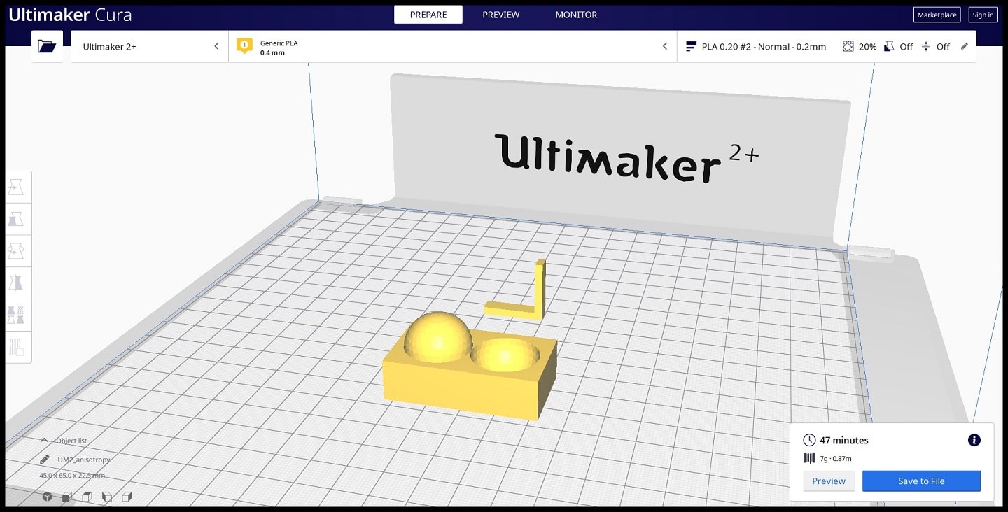
Part 4: Anisotropy and Surface Finish: This print consists of two STL files. The point is to test the quality of anisotropy and surface finish.
Step 1: Download the files “Anisotropy” and “Surface finish” STL files. If you are using Ultimaker 2+ you can download the associated gcode files and print.
Step 2: Use the following printing settings.
Quality
Layer Height: 0.20 mm
Line Width: 0.35 mmShell
Wall Thickness: 0.7 mm
Top/Bottom Thickness: 0.6 mmInfill
Infill Density: 20%
Infill Pattern: GridMaterial Printing Temperature: 200 °C
Build Plate Temperature: 60 °CSpeed
Print Speed: 45 mm/sTravel
Enable Retraction: YesCooling
Enable Print Cooling: Yes
Fan Speed: 100%Support
Generate Support: UncheckBuild Plate Adhesion
Build Plate Adhesion Type: Skirt
Step 3: Click on “Open File(s)” icon and select the STL file. Use “Move”, “Scale” and “Rotate” to control the position, size and orientation of your print.
Step 4: Repeat Step 6 and Step 7 in Part1.
Findings:
Surface Finish at 0.2 mm layer height shows good quality.
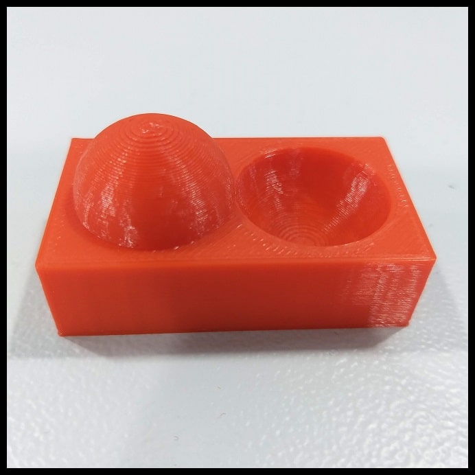
Anisotropy is having physical properties that vary with respect to direction. Item seems to show good quality and low variations.
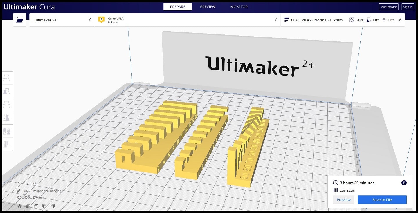
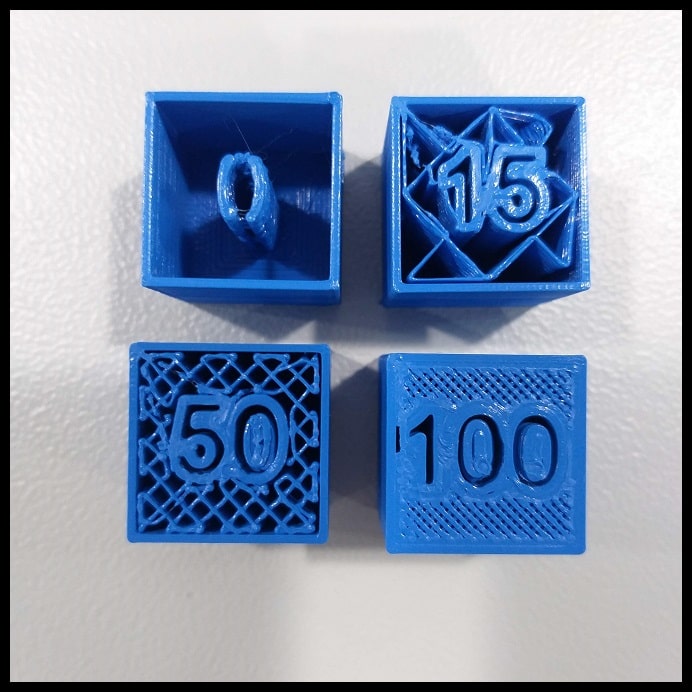
Part 5: Infill: This print consists of four STL files. The point is to test the infill of 3D printing.
Step 1: Download the files “Infill 0%”, “Infill 15%”, “Infill 50%” and “Infill 100%” STL files. If you are using Ultimaker 2+ you can download the associated gcode files and print.
Step 2: Use the following printing settings. Note that there are four prints in this parts and infill percentage should be changed for each file in each print.
Quality
Layer Height: 0.20 mm
Line Width: 0.35 mmShell
Wall Thickness: 0.7 mm
Top/Bottom Thickness: 0.6 mmInfill
Infill Density: 0%, 15%, 50%, 100%
Infill Pattern: GridMaterial Printing Temperature: 200 °C
Build Plate Temperature: 60 °CSpeed
Print Speed: 45 mm/sTravel
Enable Retraction: YesCooling
Enable Print Cooling: Yes
Fan Speed: 100%Support
Generate Support: UncheckBuild Plate Adhesion
Build Plate Adhesion Type: Skirt
Step 3: Click on “Open File(s)” icon and select the STL file. Use “Move”, “Scale” and “Rotate” to control the position, size and orientation of your print.
Step 4: Repeat Step 6 and Step 7 in Part1.
Findings:
Image below shows printing at 0%, 15%, 50% and 100% infill. Note how printing time changes as infill density increases.
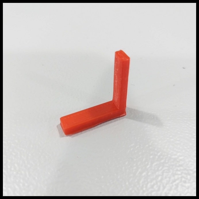
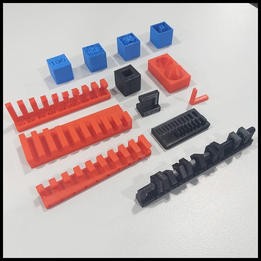
Hero Shoot!
Week Assignment
3D Design: Additive Manufacturing!
File Download
3DAdditive Fusion 360 .f3d File
3DAdditive .stl File
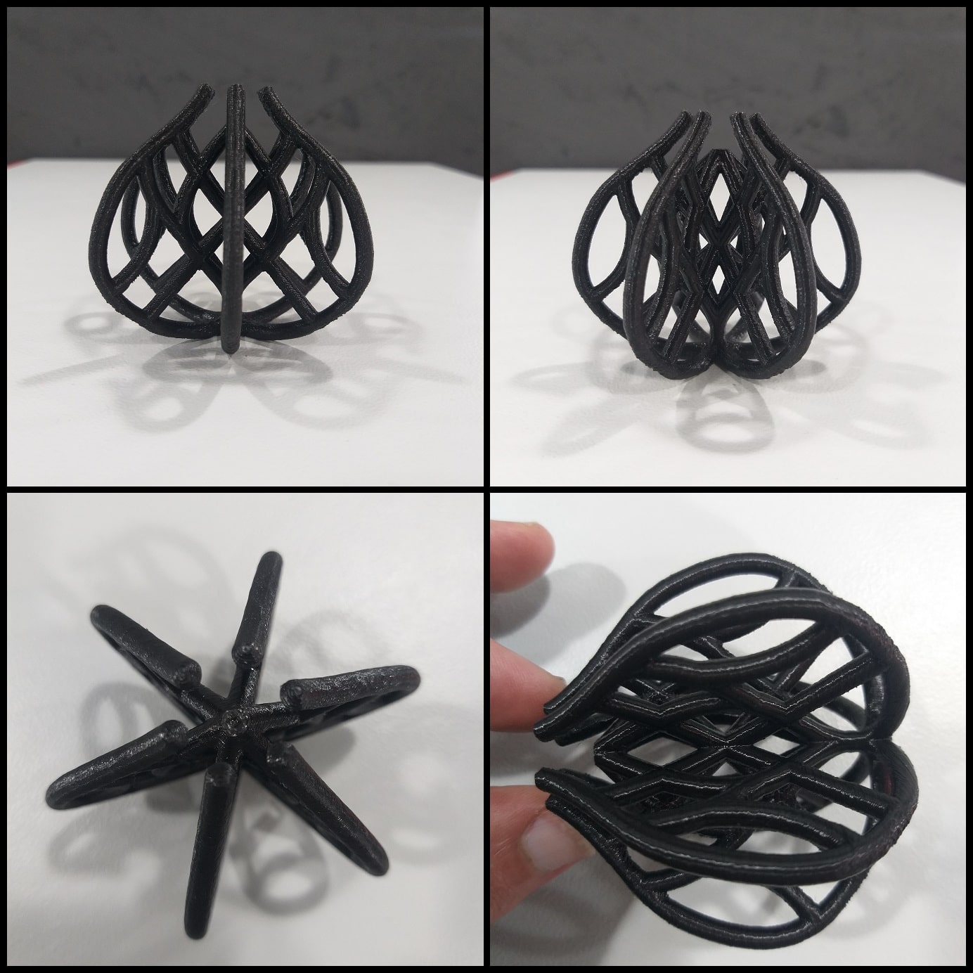
“Additive Manufacturing refers to a process by which digital 3D design data is used to build up a component in layers by depositing material.” Source.
The model I built cannot be done in the other way; using Subtractive Manufacturing. It has undercuts and nested parts which are inaccessible by a milling tool. This a good example of additive manufacturing capabilities in making complex objects.
The 3D Design
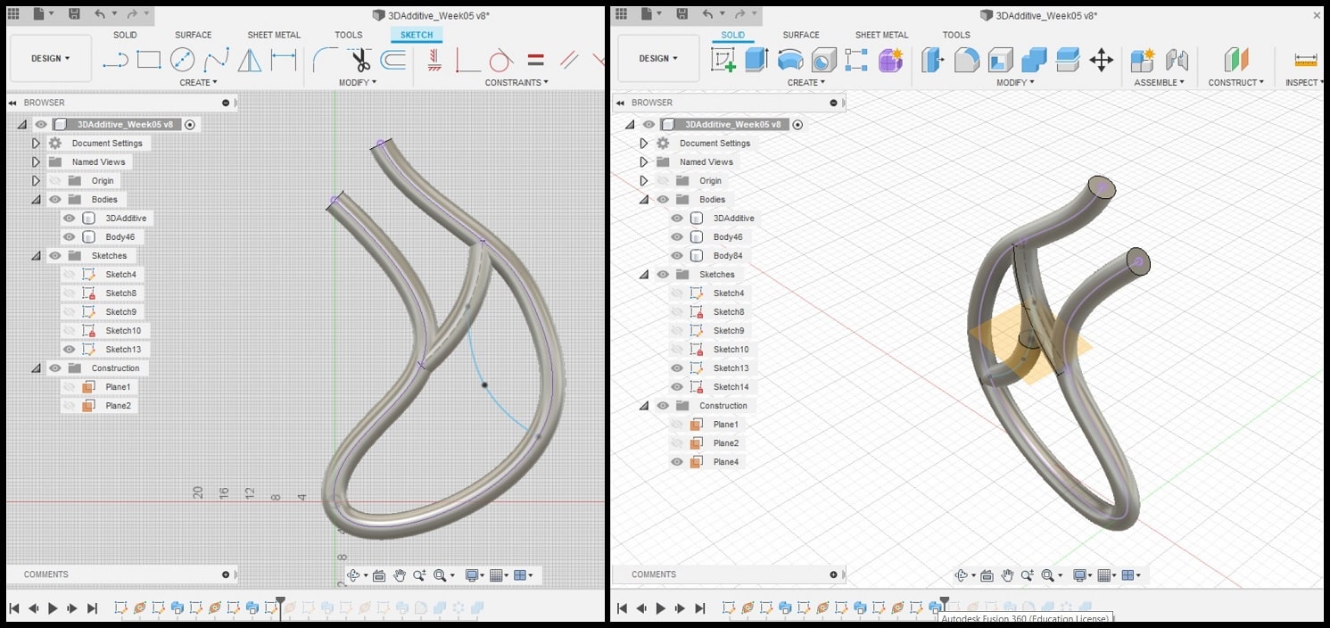
I used Fusin 360 to model the object. I created a base object then patterned it circularly. The base object itself consists of 4 bodies, each created using a single spline, then a circle sketch was swept (using sweep) through each spline.
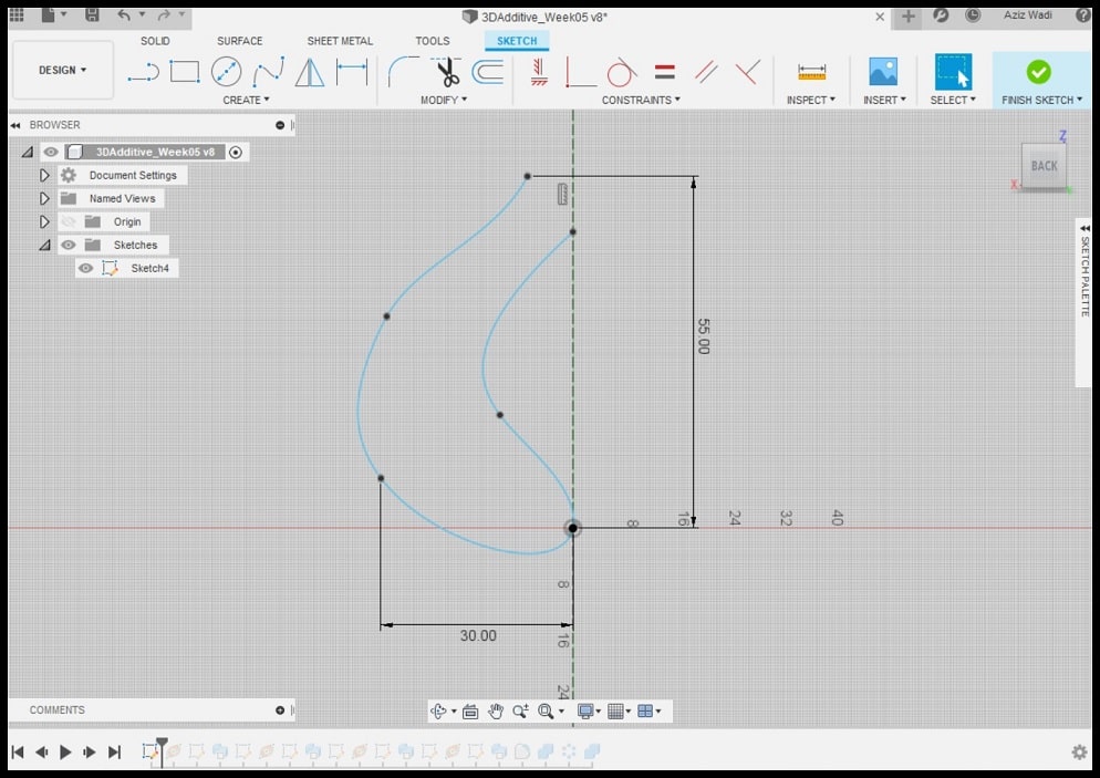
Step 1: Using the “Sketch” tool, create a sketch on the “Front” plane. Using “Line” tool, draw a construction vertical line crossing the origin. This is the axis around which the base object will be patterned circularly.
Using “Spline” tool, draw a shape to the left of the vertical line. Use “Dimension” tool to measure your extreme points. The object should be limited in size (few cm3). Finish the sketch.
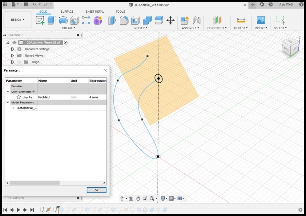
Step 2: Using “Construct > Plane Along Path”, create a plane at one of the ends of the spline line.
Using “Sketch” tool, create a sketch on the plane you just created. Using “Circle” tool, draw a circle concentric to the plane origin. The diameter is defined in “Parameters” as “ProfileD”, and it is assigned to 4.0 mm. Finish the sketch.
Step 3: Start a “Sweep” and “Edit Feature” will appear. for “Path” select the spline and for “profile”, select the circle. for “operation” choose “New Body”, this will make the result of the sweep as a new body. This is the first body in the base object.
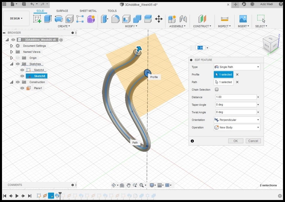
Step 4: Repeat Step 1, Step2 and Step 3 to make the other 3 bodies of the base object.
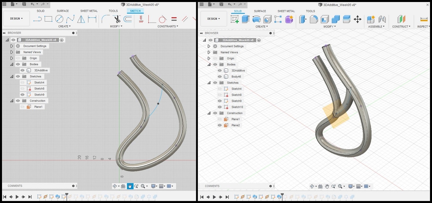
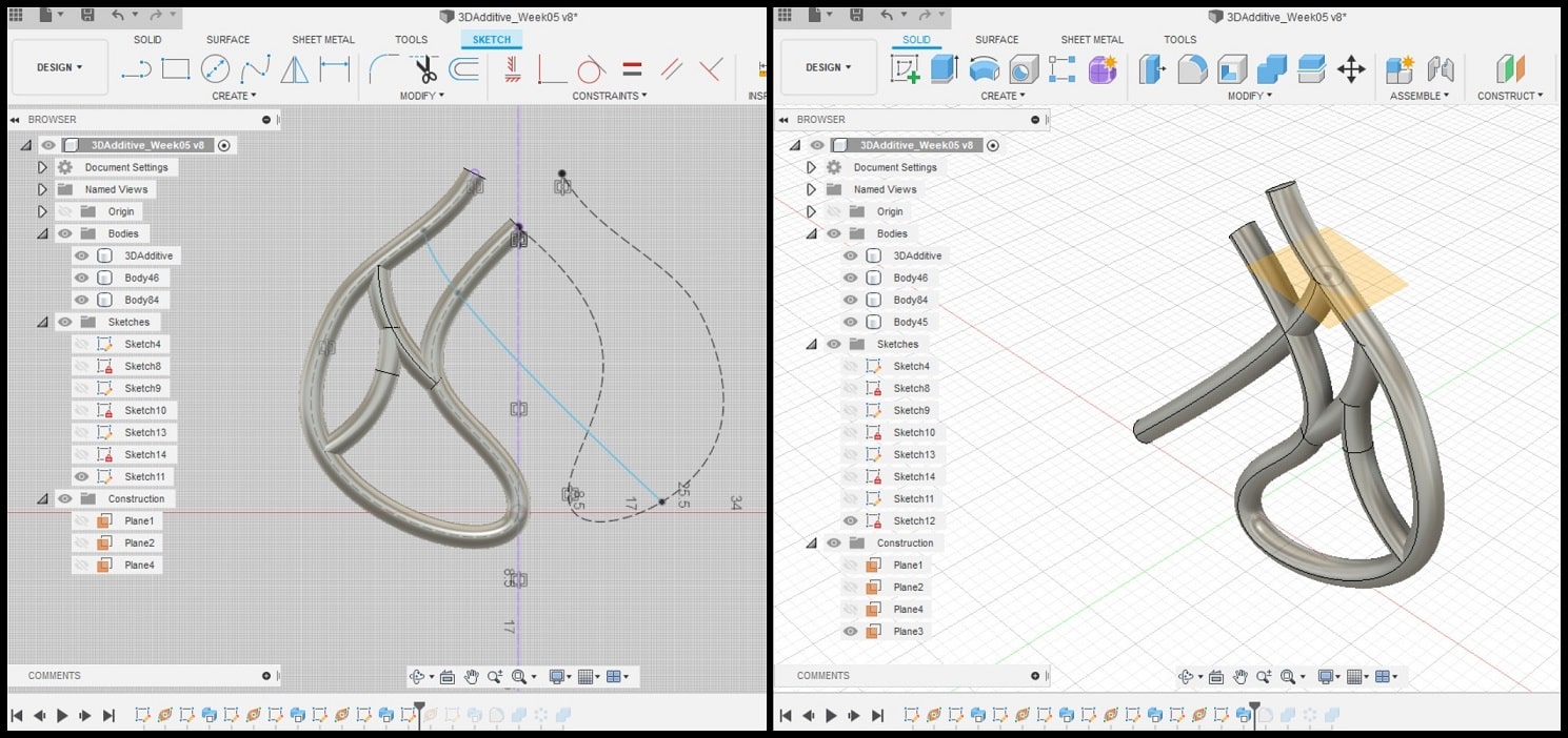
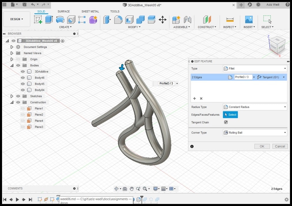
Step 5: Using “Fillet” tool, make round fillets to the top ends of the bodies. The radius is defined relative to “ProfileD” so that R = ProfileD / 3.
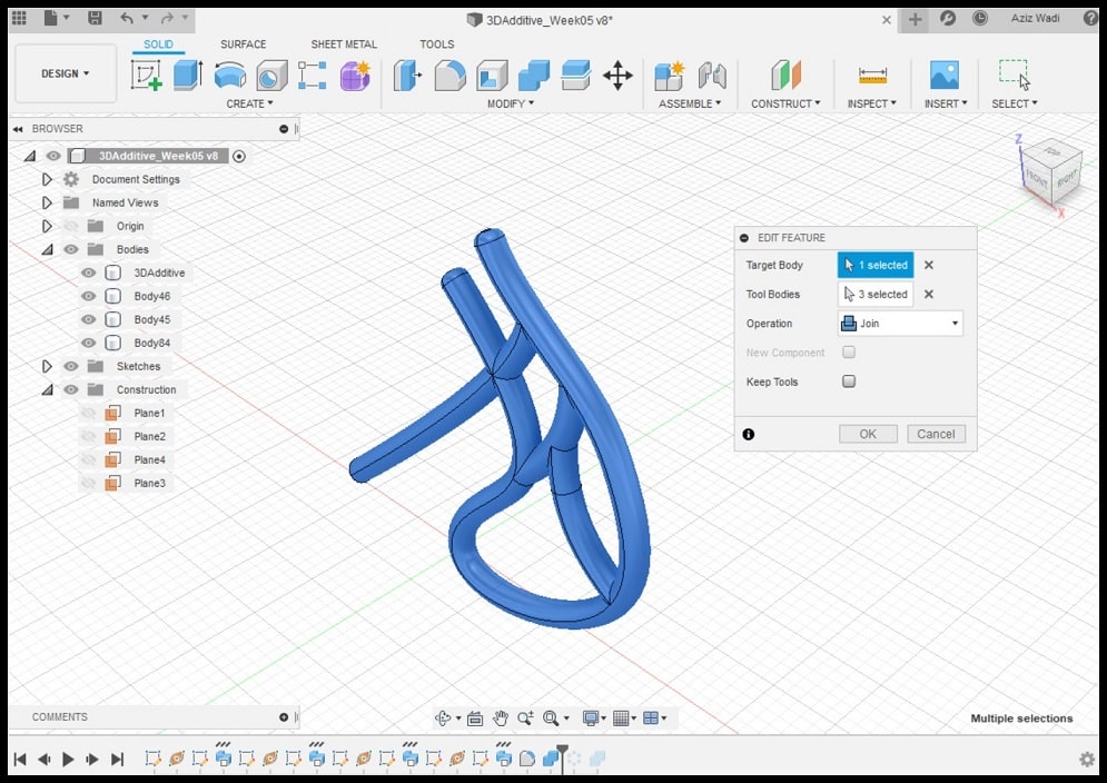
Step 6: Select the four bodies and using “Combine” tool and select “Joint”. This will combine the four bodies into a single one. This will make it easier to do the circular pattern.
Step 7: Using “Create > Patter > Circular Pattern”, for “Objects” select the base body and for “Axis” select the vertical axis created in Step 1. For “Quantity” you can put 6 or 8, I chose 6.
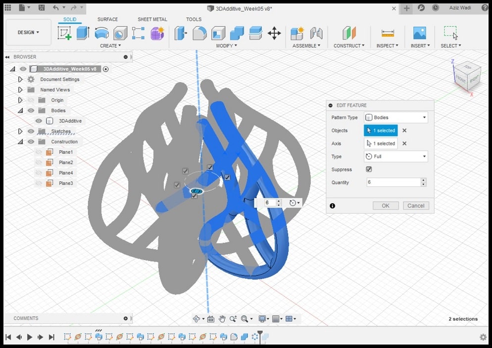
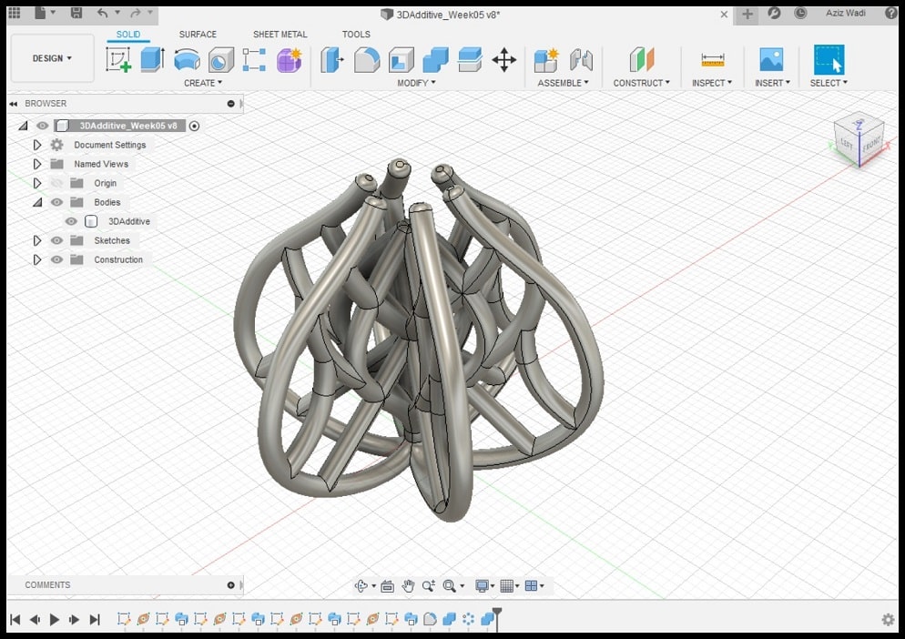
Step 8: Select all result bodies and using “Combine” tool and select “Joint”. This will combine bodies into a single one. This will be used to save the object as STL file for 3D printing. Rename the result to “3DAdditive”.
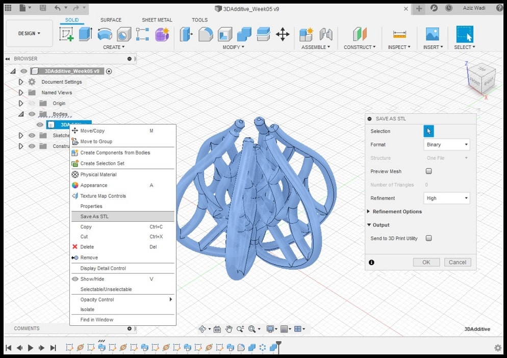
Step 9: To save STL copy of the object, right click on the body’s name and select “Save As STL”. For the format select “Binary” and for “Refinement” I chose “Fine”. Now we are ready to work on the slicing software to 3D print our model.
Slicing for 3D Printing
I used Ultimaker Cura to slice the STL file and PLA filament to print the object.
Step 1: Open Cura and import STL from previous section. Use “Move”, “Scale” and “Rotate” commands to work on the position, size and orientation of the STL file. Select machine, which is “Ultimaker 2+” in my case. For material select “PLA” and “Nozzle” 0.4 mm.
Step 2: Open “Print Settings” and click on “Custom”. Change printing settings as described below.
Quality
Layer Height: 0.20 mm
Line Width: 0.35 mmShell
Wall Thickness: 0.7 mm
Top/Bottom Thickness: 0.6 mmInfill
Infill Density: 0%, 15%, 50%, 100%
Infill Pattern: CubicMaterial Printing Temperature: 200 °C
Build Plate Temperature: 60 °CSpeed
Print Speed: 45 mm/sTravel
Enable Retraction: YesCooling
Enable Print Cooling: Yes
Fan Speed: 100%Support
Generate Support: Check
Support Placement: Everywhere
Support Overhang Angel: 60°
Support Pattern: ZigZagBuild Plate Adhesion
Build Plate Adhesion Type: Brim
Step 4: Click on “Slice” and Cura will slice your object and show time will take to 3D print, grams of PLA filament needed and length in meters of PLA filament needed.
Step 5: Click on “Preview” tab. Here you can move the vertical slide and check the print layer by layer. It is a good practice to review supports used and how the object will be built. The STL was sliced into 307 layers.
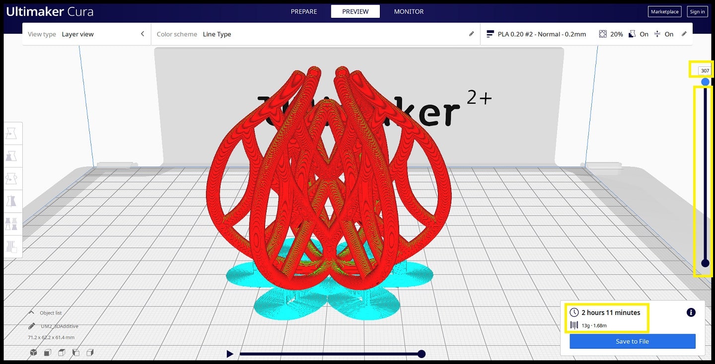
The clip below shows the layer-by-layer process. Brim and support appear in blue.
3D Printing
Copy the gcode file to printer storage media. Make sure that the correct material (PLA 2.85 mm) and nozzle (0.4 mm) are used on the printer. Click on “Print” then find your model and press on the knob to select it and start printing. Printing will start heating up. When it is done printer will start printing and show remaining time.
Hero Shoot!
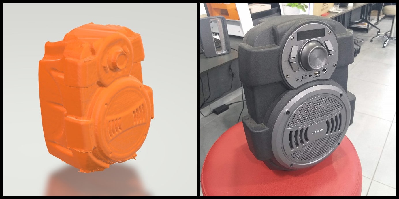
3D Scanning
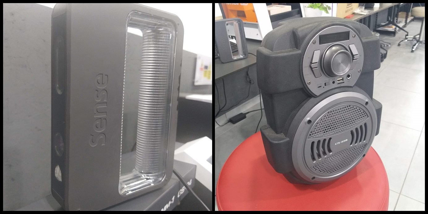
3D Scanner: Sense 1st Generation
Software: 3DSystems Sense
File Download
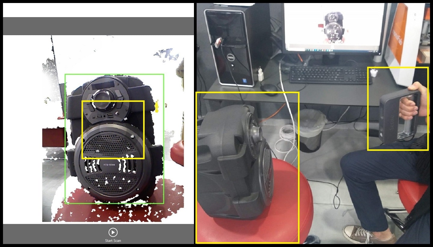
In this part I scanned a small object using Sense 3D scanner and Sense software. Image below shows the scanner and the object I scanned.
Step 1: Open the Sense software for Sense 3D scanner. Select type of scan (Person or Object), then select the size of object to be scanned. In our case it is a small object.

Step 2: Put your object on a rotating base if possible. Hold the scanner in front of the object. Move forward and backward till you have a good view and a green rectangle surrounding the object. Make sure that the object is centered to the circle appears in software screen. Stay still at your position holding the scanner. Ask your colleague to press on “Start Scan”.
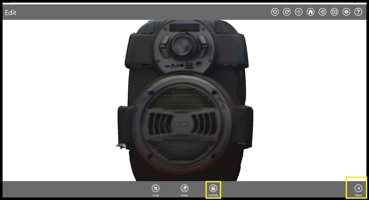
Step 3: Ask your colleague to rotate the base slowly till a complete turn is completed. When it is done, click “Next” to finish scanning and move to next step. Now the scan is hollow and should be solidified. Click “Solidify” to fill in the scan. Click “Next”.
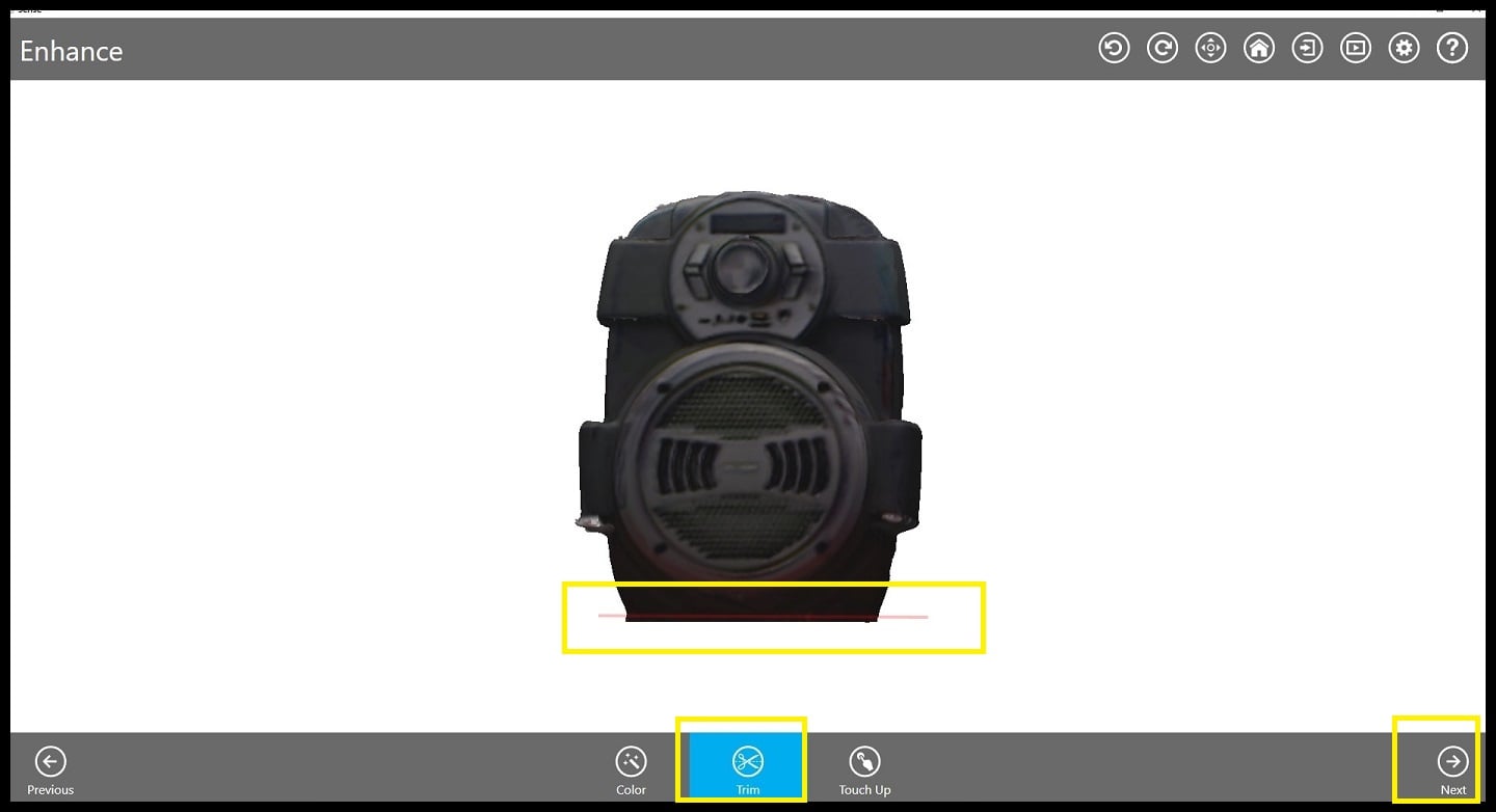
Step 4: Using “Trim” tool, draw a straight line at the bottom of your scanned object to make sure it will have a flat base for 3D printing. Click “Next”.
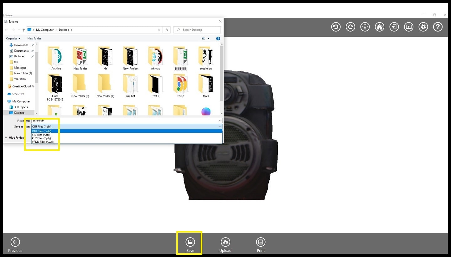
Step 4: Click on “Save” and select file type. I saved my scan as STL file.
Hero Shoot!