3. Computer Aided Design
In this part I worked on 2D vector design using Inkscape, and 3D modelling using Fusion360. 3D modelling will be needed in my final project, to make the casing for main measuring unit and fan control unit. Each unit will have extrudes to fix PCBs inside, opening for controls and displays, and should be at the right size. All those design requirements, benefiting from this week, will be considered in the 3D model. Working in 2D design makes all of this easier by 2D projecting units openings and right locations and then build-on the 3D model.
2D Design
File Download
Inkscape Mandala file (Click to download)
Inkscape vector graphics editor
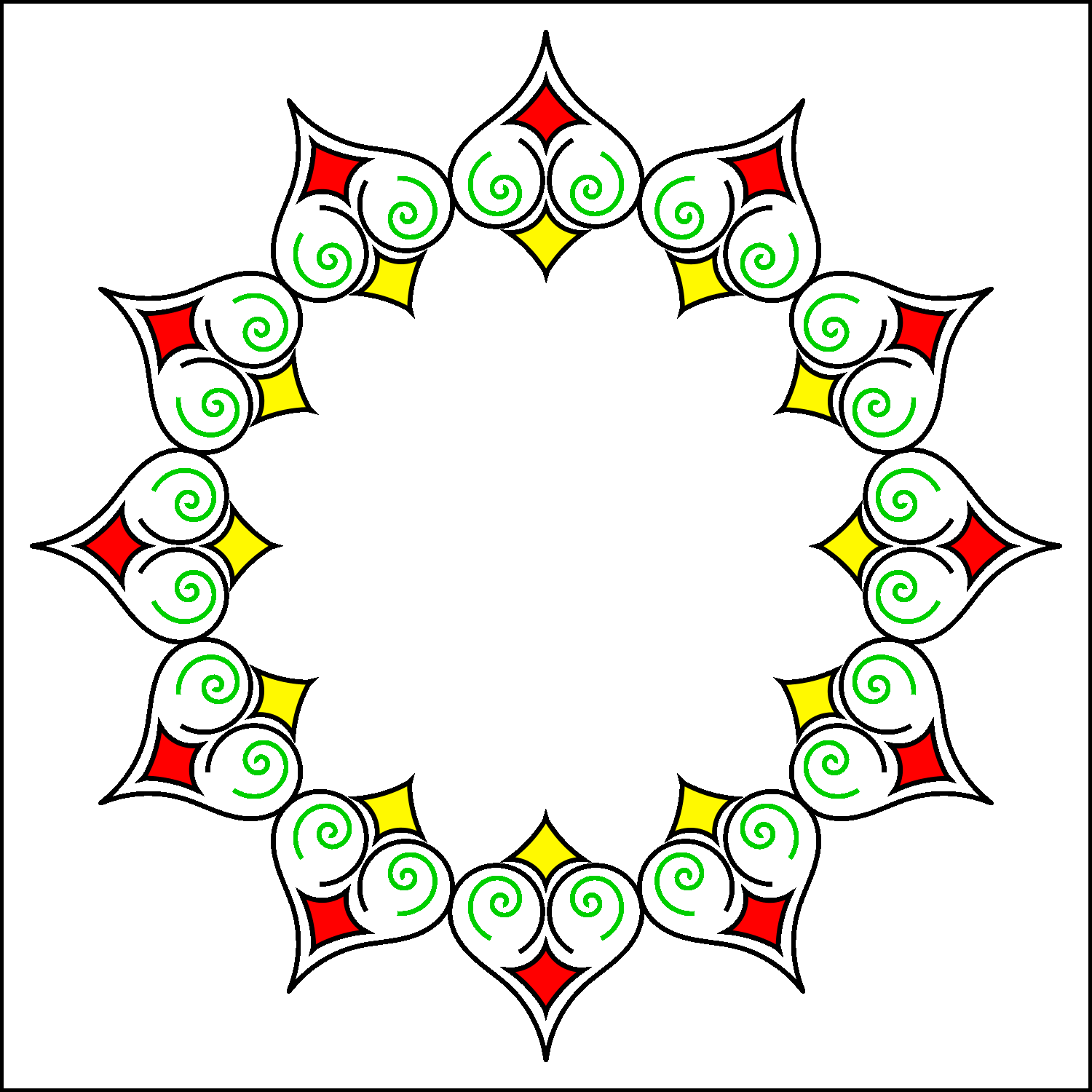
“Inkscape is professional quality vector graphics software”. I worked on creating a simple Mandala where I used many tools and techniques in Inkscape.
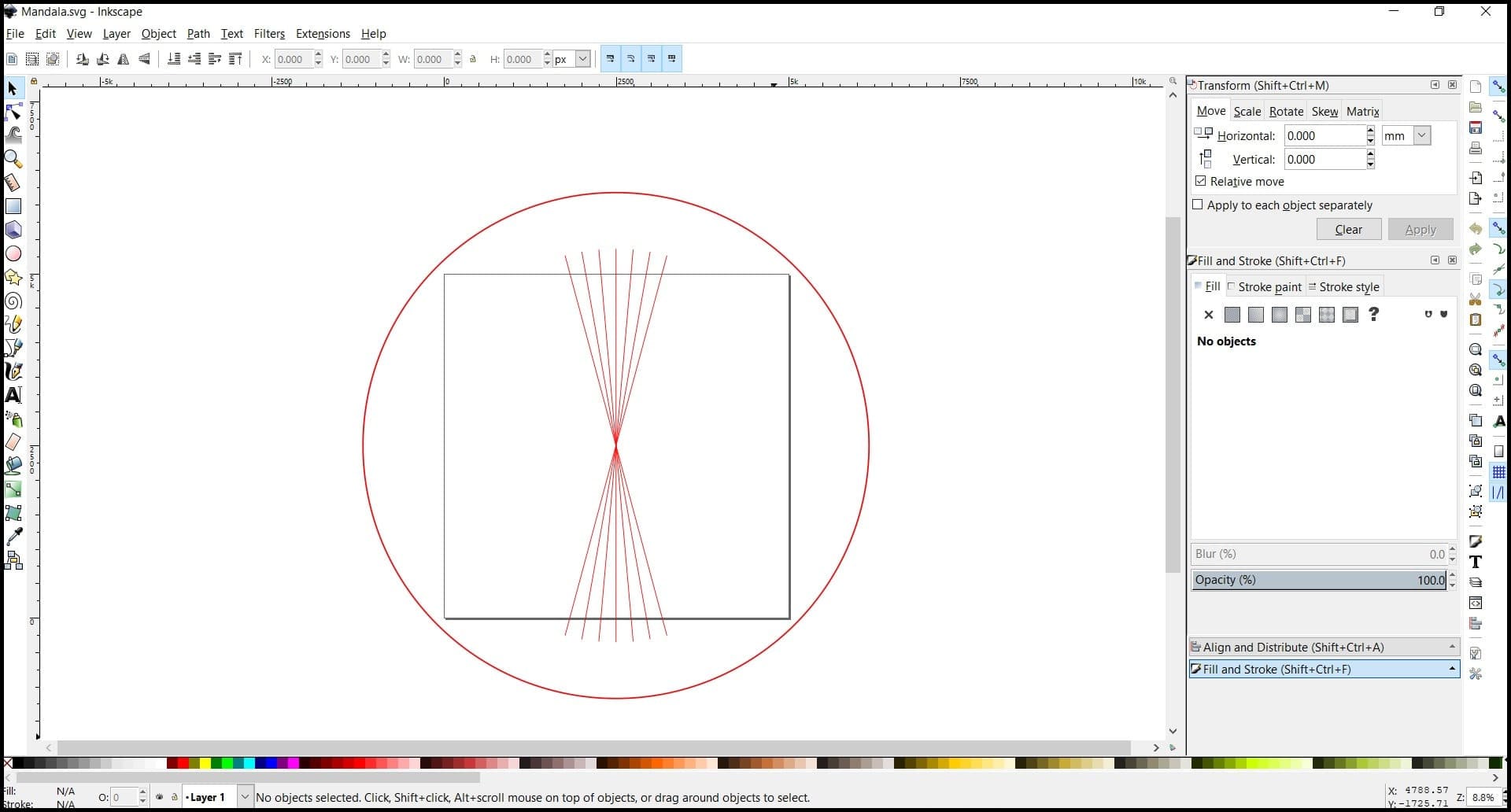
I created a new document and customized size to 5000x5000 px.
Then, I set up guide objects. The first object is a circle that surrounds the document and centered to it. I used the “Create circle” tool to make this object. This object was used to rotate the parent pattern of the Mandala around the document center.
The second object are 15 Deg spaced lines. I used the “Draw Bezier” to create these lines. The lines were used to control the angle occupied by the parent object (30 Deg).
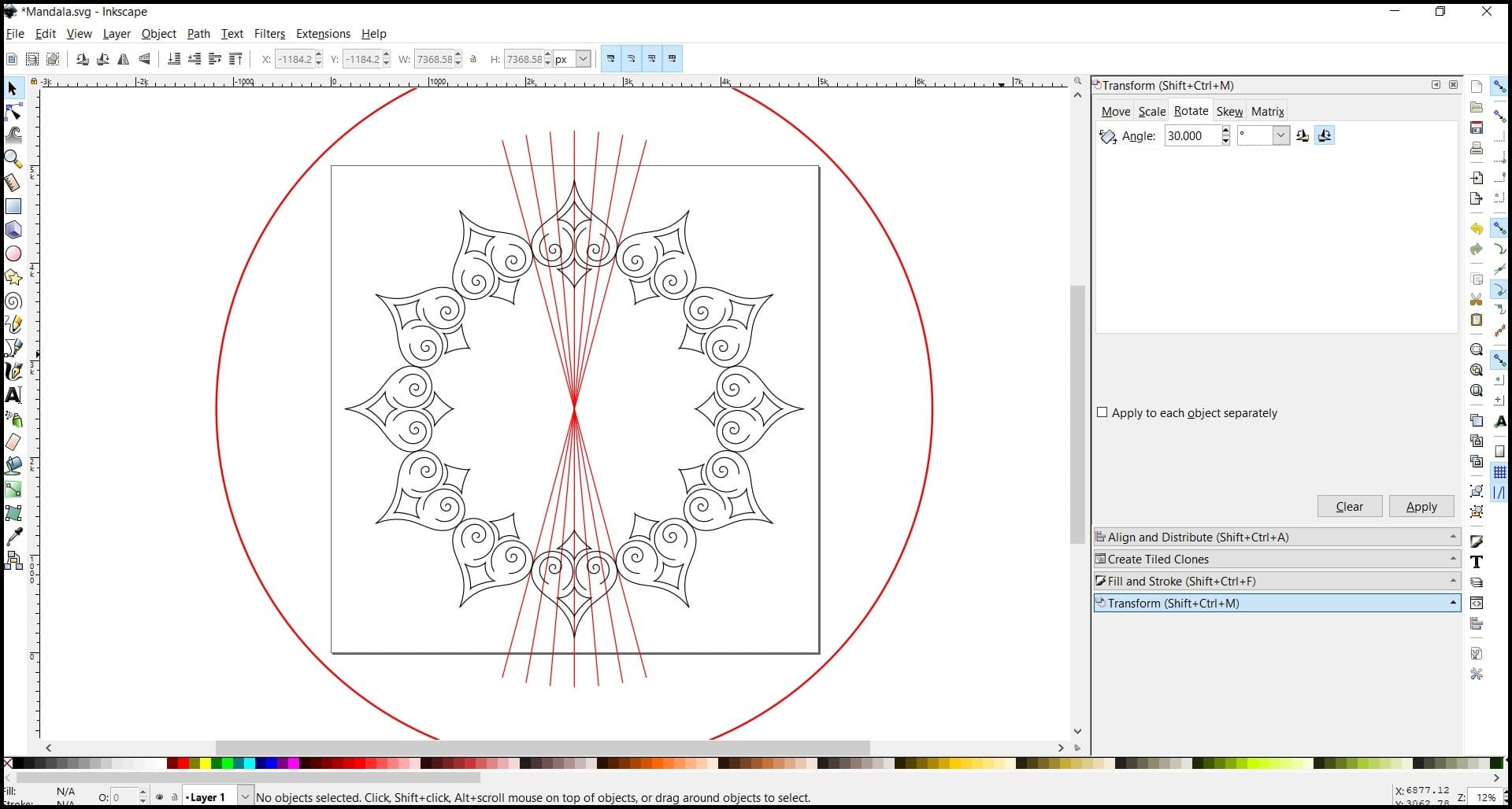
In the next step I started to create the parent pattern. I used “Draw Bezier” to create this pattern and then worked on fine editing. I worked on the right part then duplicated it and vertically flipped it. Then the right and left part were joined and centered horizontally.

The parent pattern then cloned and each clone was rotated 30 Deg away from the previous one. The result 12 patterns (1 parent pattern, 11 cloned), each pattern occupied 30 Deg.
Finally, the parent pattern settings (color, stroke, filling) were changed and all changes were reflected to the clones. The result was exported as png file, and it was scaled at export to 1500x1500.
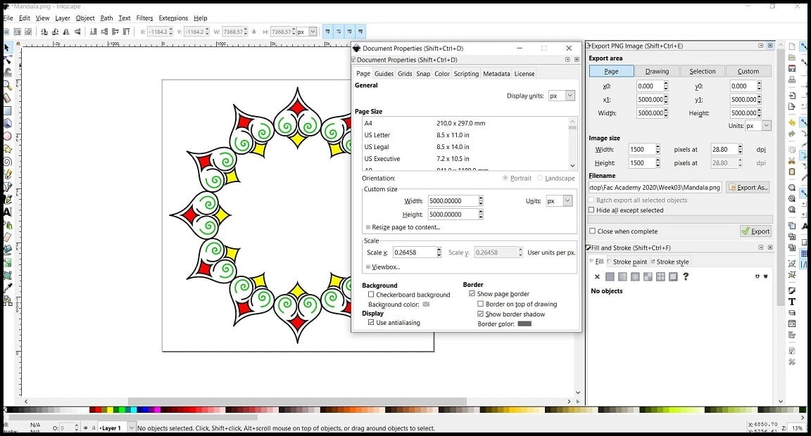
Hero Shoot!
3D Design
File Download
Fusion 360 .f3d (Click to download)
.step file (Click to download)
Fusion 360
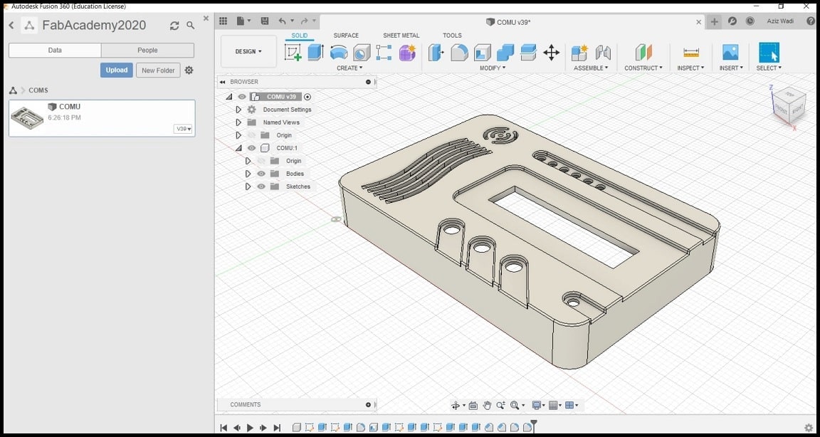
I used Fusion 360 to design the upper case of the COMU (check my final project).
In Fusion 360 everything is recorded in the timeline. You can go back to any sketch or feature you created and edit it. Changes made will affect relevant features after the editing point. Also, all bodies, component, assemblies and animation are saved in a singe file. For parametric design, you can define your variables and equations and use them in your design.
Below is the description of creating the basic part of the upper cover of COMU where all input and output parts will be fixed.
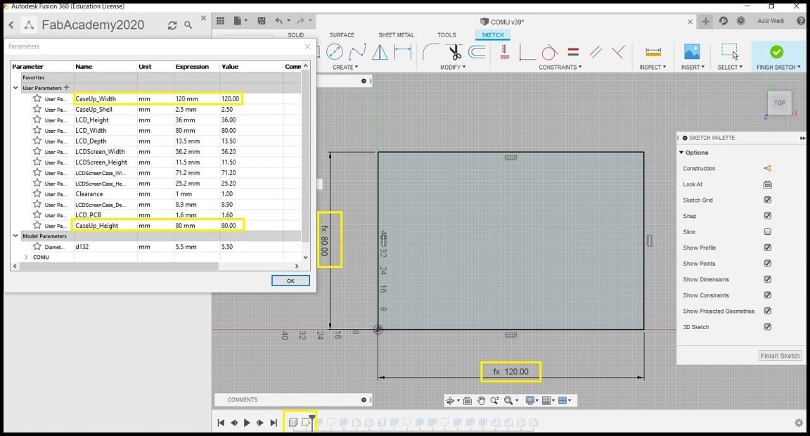
Step 1: First I created a new empty component and made it active. Using “Create Sketch” command, I created a sketch on the top plane. The sketch is used to make the raw upper cover where other features were applied.
Cover width and height were saved as parameters in Fusion 360. If the size of the cover is to be changed, this can be achieved by changing height and width values in parameters.
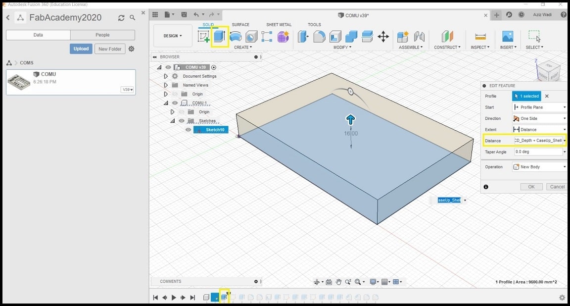
Step 2: Using “Extrude” command, the base sketch was extruded to fit inside the LCD. Extrude height is defined as a function of LCD height and shell or thickness value of the cover. Both values are defined as parameters. The extruded body was saved as a new body inside the component created in step 1.
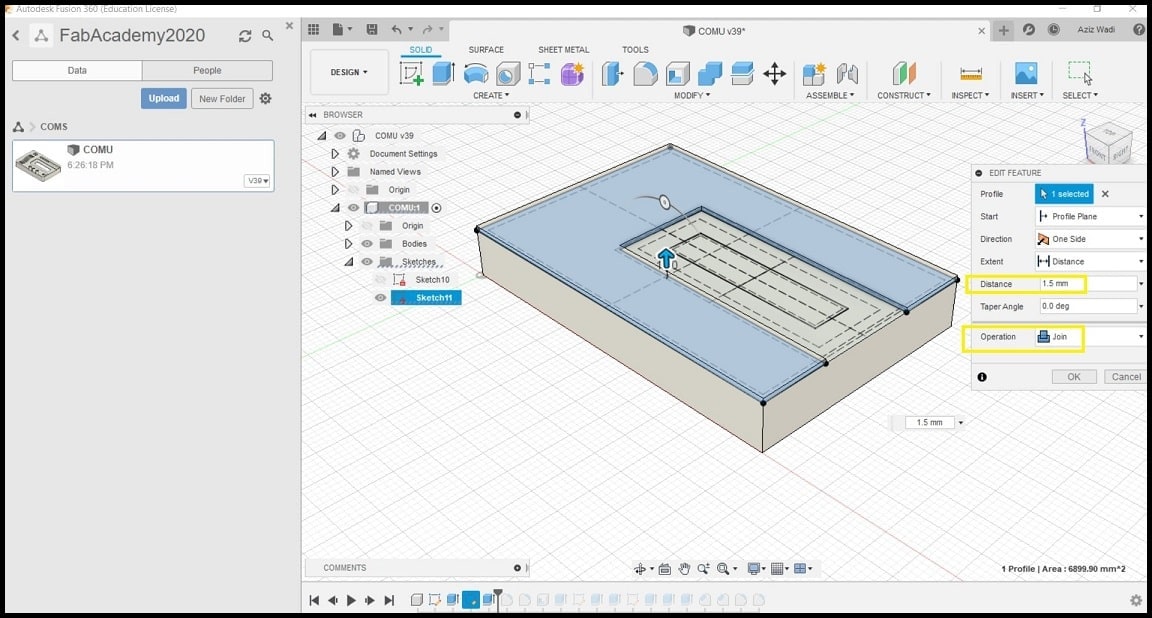
Step 3: Since the cover was created to have enough space for the LCD from inside, the next feature was added to the top surface. Using “Create Sketch”, a sketch was created on the top surface of the part. In this sketch there are construction sketches and areas to be extruded. All dimensions were defined as parameters. Using “Extrude” command, a 1.5 mm of material was added to the top surface as defined by the region shown in image below. Note that sketch color is in black, which means that sketch is fully defined.
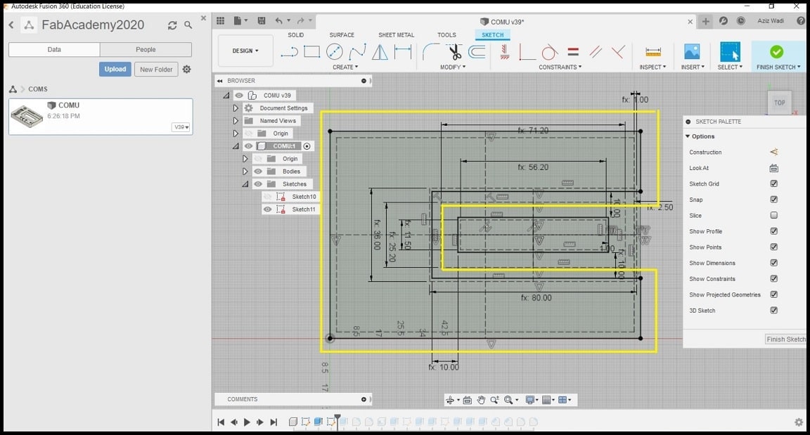
Step 4: Using “Extrude” command, the region was extruded 1.5 mm up. New material was joined to the existing model, so no new body was created.
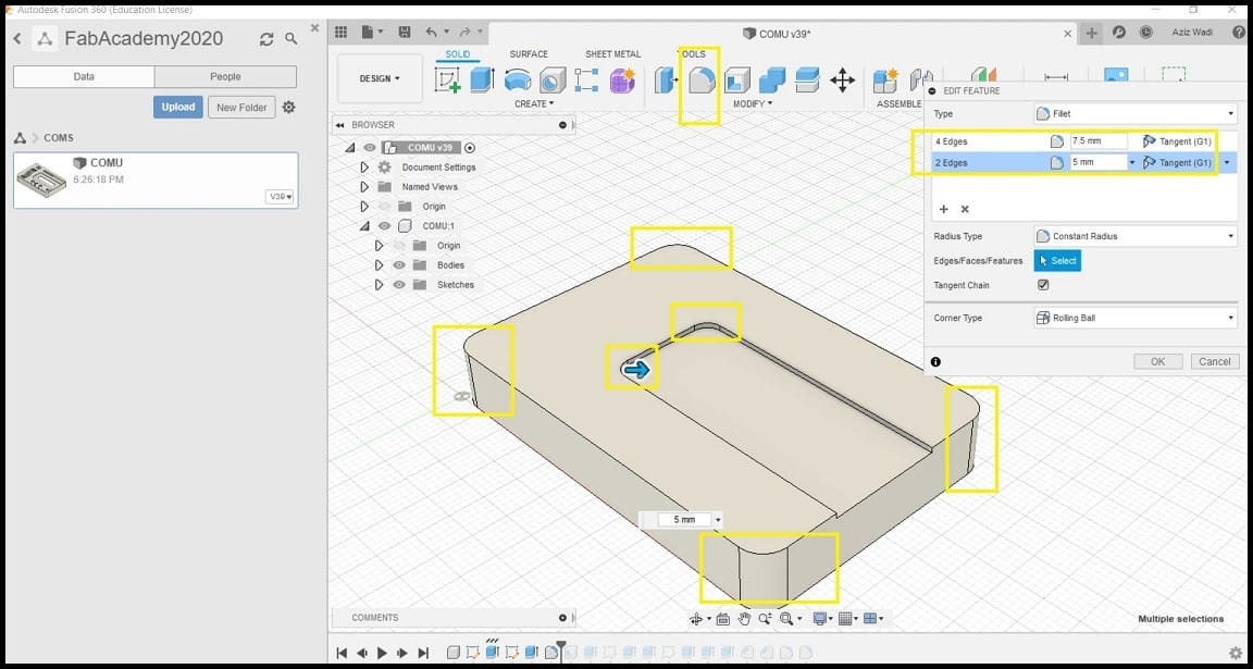
Step 5: Using “Fillet” command, outside body corners were rounded by 7.5 mm (4 edges), and the corners where the LCD were rounded by 5 mm (two edges).
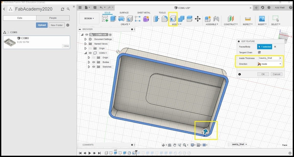
Step 6: Using “Shell” command, the upper case body was shelled from the bottom surface. It was important to make the 1.5 mm extrude and fillets before the shell so they would be included in the final shape. The thickness of shell was defined in parameters table.
Step 7: Using “Extrude” command and the sketch created in step 3, a cut was made for the LCD screen. The size of the rectangle was defined in parameters.
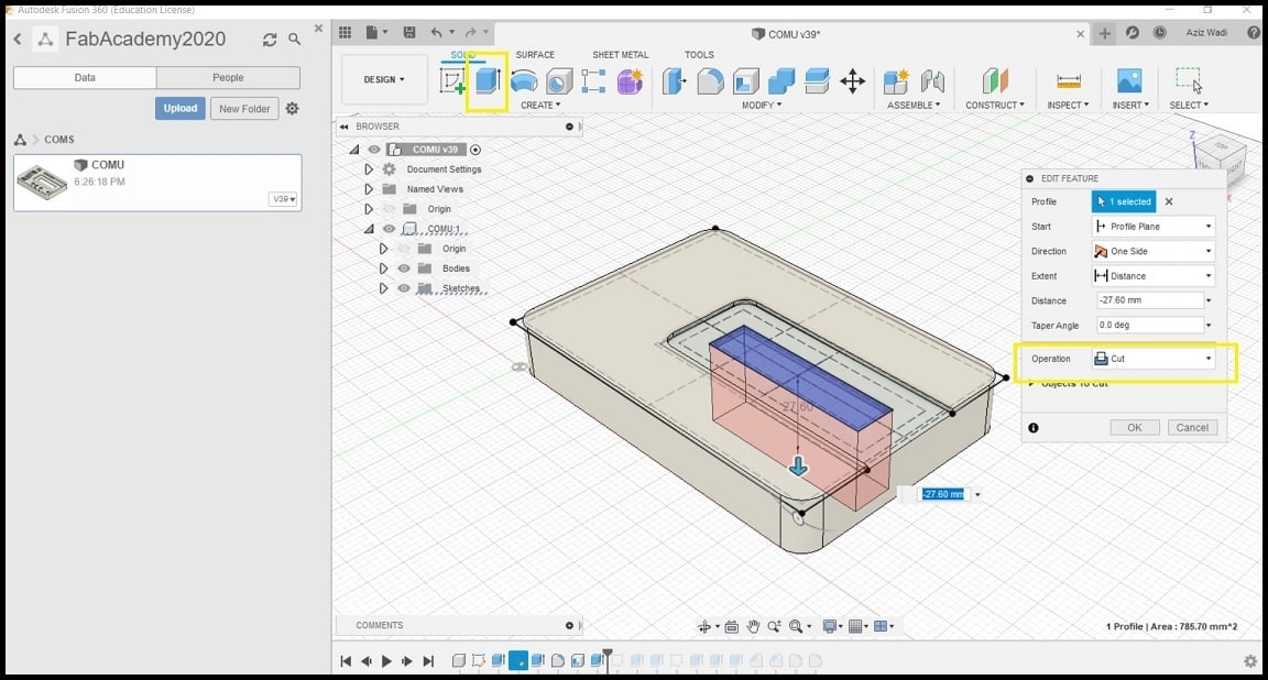
The same steps where used to create and refine the opening for LEDs, push button, buzzer, CO sensor and temperature sensor. Note that all operations are saved in the timeline.
Hero Shoot!