13. Interface and Application Programming
Group Assignment
Useful Links
Python
Processing
Firefly
MIT App Inventor
Due to COVID-19 lock down, we completed this part in a group call, where we discussed Python, Processing, Firefly and MIT App Inventor.
Python: a lot of packages are available to build applications like tkinter and pyserial. Usually a third-part text editor is required to code in Python, like PyCharm and Atom.
Processing: We discussed how we can build a graphical interface and connect it to Arduino board, where the graphical interface would interact with an input device connected to the board.
Firefly: it is used to connect between Grasshopper, Arduino board and input and output devices.
MIT App Inventor: it is an east way to create functional applications for smartphone and tablets.
Week Assignment
In this week I will connect the HC-SR501 PIR Sensor to ATtiny44 Development Board. The reading of the sensor, in addition to development board LEDs will be displayed and controlled using Python graphical user interface GUI. For more information about HC-SR501 PIR Sensor and ATtiny44 Development Board please check Input Devices Week
File Download
Python 3
Atom
GUI Python File
C and Makefile
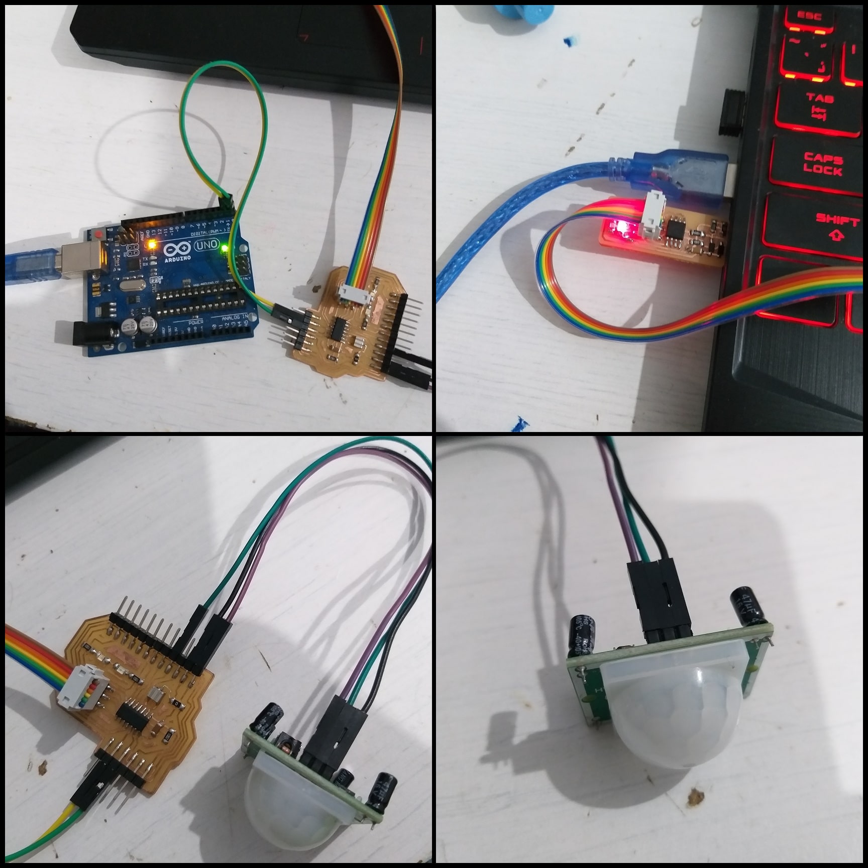
The Hardware
The ATtiny44 Development Board allows connection to all I/O pins and also Vcc and GND. It has FTDI header which is connected to Arduino UNO board to replace FTDI cable. The table below shows connection between input, UNO board and the ATtiny44 Development Board.
| ATtiny44 Development Board | HC-SR501 PIR | UNO Board |
|---|---|---|
| Board LED blue PA5 | ||
| Board LED red PA6 | ||
| PB2 | OUT | |
| Vcc | Vcc | Vcc |
| GND | GND | GND |
| Rx (PA0) | Tx | |
| Tx (PA1) | Rx |
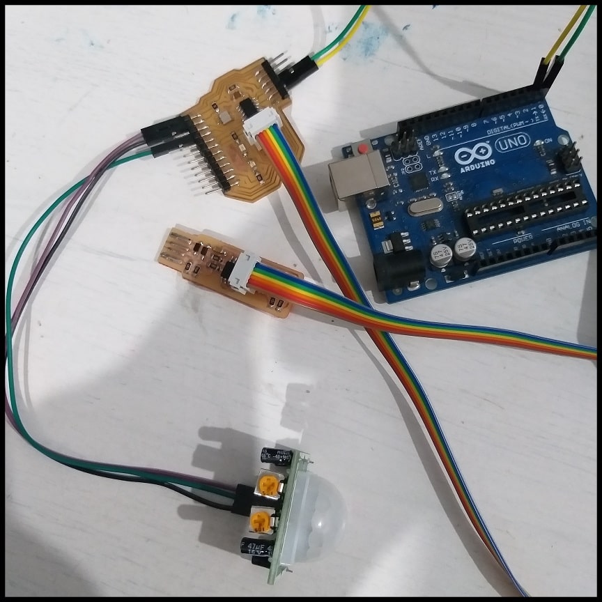
Note that the jumper on programmer board is soldered, so power is supplied from USB to the ATtiny44 Development Board through the programmer. Arduino UNO board is connected to USB as well, which makes the whole system have the same Vcc and GND.
Installing pyserial Package
To enable communication between the GUI application and board, I used pyserial serial communication package. This should be installed to Python as it is not included by default.
Step1: Go to Python page and install python to your PC. I am using Python 3.8.2 under Windows. After completing check Python version using Windows Command Prompt using the command “python –version”. To check what packages are installed to your Python, type “pip list”.
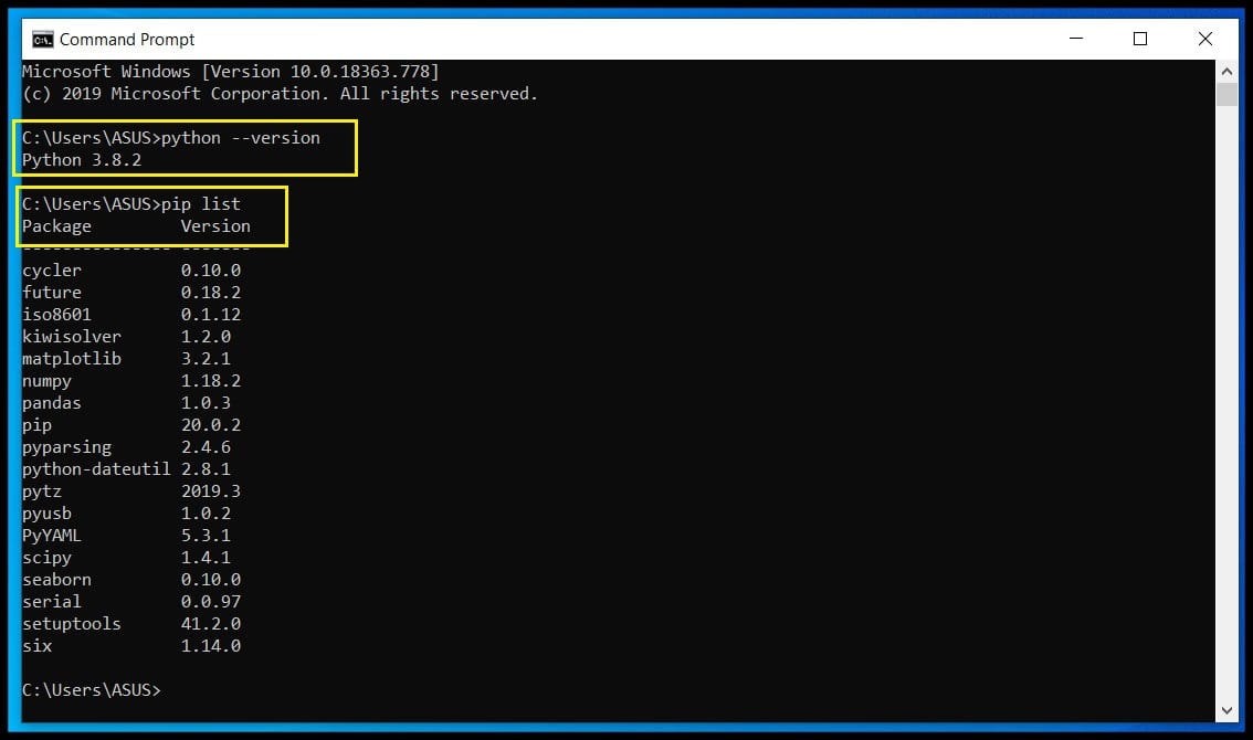
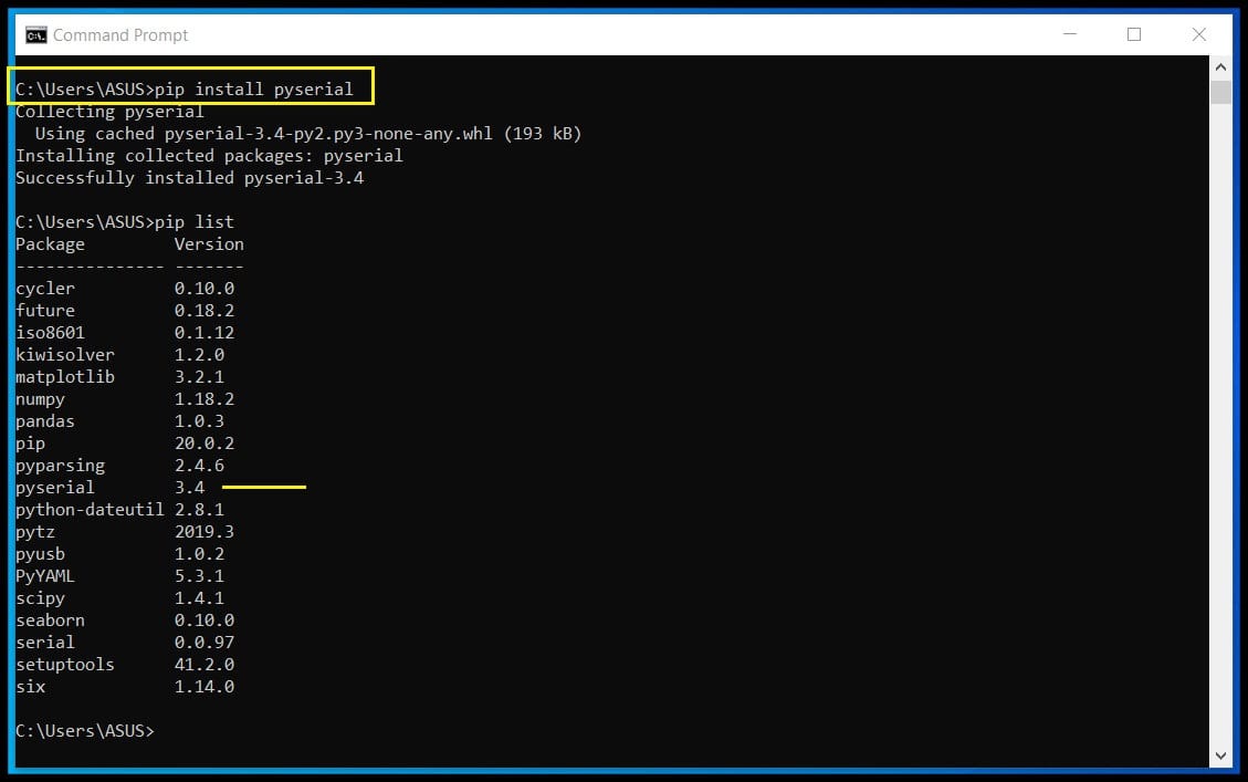
Step2: The list shows that pyserial is not installed to Python. Type “pip install pyserial” to istall the package. Now pyserial 3.4 package is installed.
Atom as Python IDE
I used Atom to write and run Python codes. After installing Atom, we need to install a package that allows to run Python code from Atom.
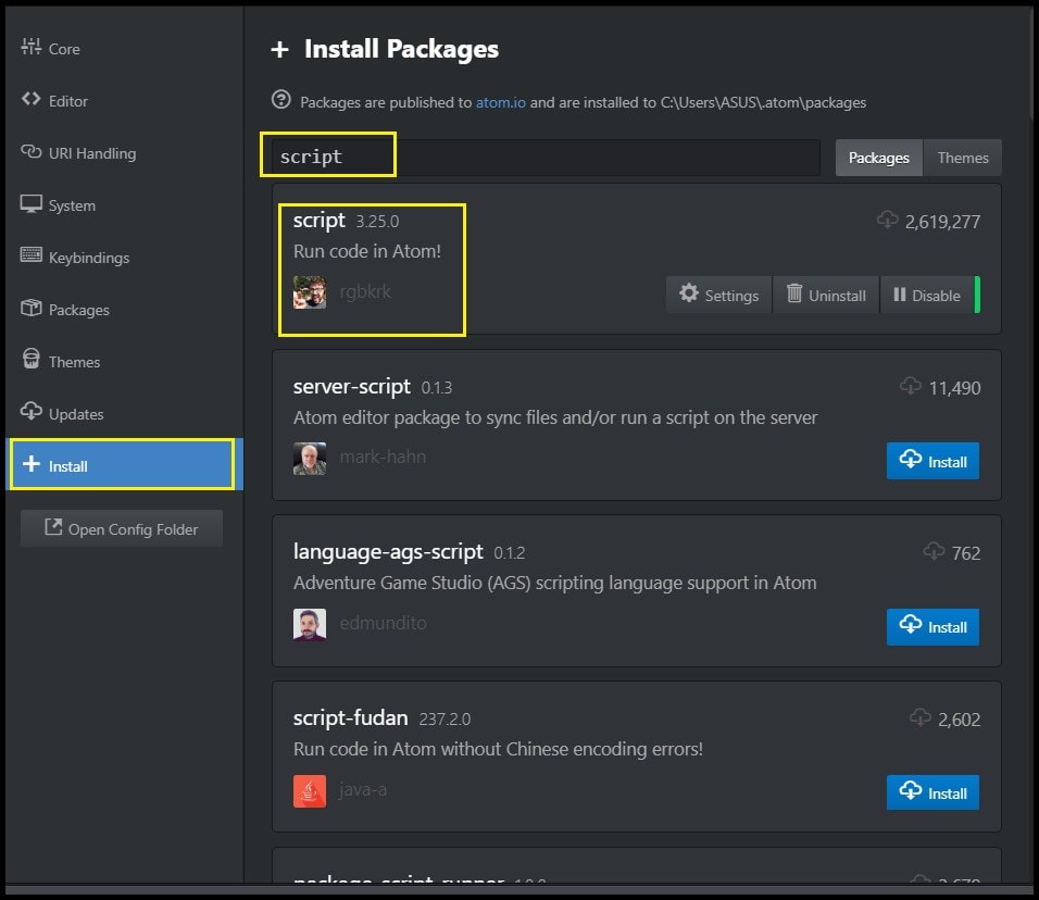
Step 1: Install and open Atom. Go to “File > Setting > Install”. In search package field, type “script”.
Step 2: Click install next to script package by “rgbkrk”. When installation complete restart Atom.
Step 3: To write a Python code, create a new file and save it adding .py to the end of name. To run code, press “Ctrl + Shift + B”.
Python Code
The Graphical User Interface
To create the GUI I used tkinter package. By using this package, you can create Windows application and add widgets like buttons and labels. This package is installed with Python by default.
The GUI I created has 5 components:
1. tkinter.TK() instance: The main or parent container where all other components will be contained. The code below will create the object “root” as instance of type tkinter.TK() and set its settings.
import tkinter as tk
root = tk.Tk()
root.resizable(0, 0) #Window is not resizable
root.title("Application Programming!")
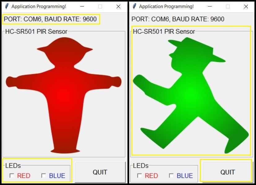
2. Label widget: Used to display communication port information as defined in the code, in my case “PORT: COM6, BAUD RATE: 9600”. The code below creates “serLabel” as instance of type tk.Label and its master or parent is “root”. Note that the label widget is expanded over 2 columns using columnspan = 2 inside “grid” method.
com = "COM6"
bRate = 9600
txt = "PORT: {}, BAUD RATE: {}".format(com, bRate)
serLabel = tk.Label(root, text = txt, font = "bold",
    borderwidth = 2, anchor = tk.W)
serLabel.grid(row = 0, column = 0, padx = 5, pady = 5,
    sticky = tk.W + tk.E + tk.N + tk.S, columnspan = 2)
3. Checkbutton widgets: Used to turn board LEDs on/off. Both widgets (RED, BLUE) are contained in a labeled frame (LEDS). The code below creates ledFrame as instance of type tk.LabelFrame and its parent is “root”. Then two check buttons redChBtn and blueChBtn are created as instances of type tk.Checkbutton and their parent or container widget is “ledFrame”.
ledFrame = tk.LabelFrame(root, text = "LEDs", font = "bold", borderwidth = 2,
    labelanchor = tk.NW, relief = tk.GROOVE)
ledFrame.grid(row = 2, column = 0, padx = 5, pady = 5,
    sticky = tk.W + tk.E + tk.N + tk.S, columnspan = 1)

redVar = tk.IntVar()
redVar.set(0)
redChBtn = tk.Checkbutton(ledFrame, text = "RED", width = 4, fg = "red",
    font = "bold", variable = redVar, indicatoron = 1)
redChBtn.pack(side = tk.LEFT, padx = 2, pady = 2, expand=tk.YES, fill=tk.X)

blueVar = tk.IntVar()
blueVar.set(0)
redChBtn = tk.Checkbutton(ledFrame, text = "BLUE", width = 4, fg = "blue",
    font = "bold", variable = blueVar, indicatoron = 1)
redChBtn.pack(side = tk.LEFT, padx = 2, pady = 2, expand=tk.YES, fill=tk.X)
4. Button widget: Used to quit the GUI and terminate the program. The code below creates “btnQuit” as instance of type tk.Button, and its parent is “root”. When this button is clicked, function “quit” is called, which performs clean up actions (turns the LEDs off and closes the serial port) before terminating the program.
def quit():
    ser.write(bytes([0]))
    ser.close()
    root.destroy()
btnQuit = tk.Button(root, text = "QUIT", font = ("bold", 13), width = 10,
        anchor = tk.CENTER, command = quit)
btnQuit.grid(row = 2, column = 1, padx = 5, pady = 5,
        sticky = tk.W + tk.E + tk.N + tk.S, columnspan = 1)
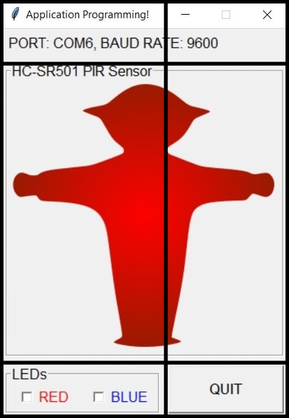
5. Canvas widget: Used to display the PIR status. If motion detected a green walking man will be shown, otherwise a red still man will be shown. The canvas is contained in a labeled frame (HC-SR501 PIR Sensor). The code below creates “PIRCanvas” as instance of type tk.Canvas and its parent is “PIRFrame”. The “PIRFrame” is instance of type tk.LabelFrame and its parent is “root”. Images to be displayed in the canvas are loaded from the hard drive and they are saved in the same folder where the code exists.
imStop = tk.PhotoImage(file = "stop.png")
imMotion = tk.PhotoImage(file = "motion.png")
PIRFrame = tk.LabelFrame(root, text = "HC-SR501 PIR Sensor", font = "bold",
    borderwidth = 2, labelanchor = tk.NW, relief = tk.GROOVE)
PIRFrame.grid(row = 1, column = 0, padx = 5, pady = 5,
    sticky = tk.W + tk.E + tk.N + tk.S, columnspan = 2)

PIRCanvas = tk.Canvas(PIRFrame, width = 310, height = 310)
PIRCanvas.pack()
PIRCanvasW = int(PIRCanvas.cget("width")) / 2
PIRCanvasH = int(PIRCanvas.cget("height")) / 2
imgIndx = PIRCanvas.create_image(PIRCanvasW, PIRCanvasH, anchor = tk.CENTER,
    image = imStop)
Note that the root window is divided into 3 rows and 2 columns (index starts from 0). These rows and columns used in “grid” method to organize items in parent window. A single widget could be expanded over more than a row or a columns. For example, the label widget is expanded over 2 columns using columnspan = 2 inside the “grid” method. Rows height and columns width have not to be equal.
The Serial Communication
The code below imports the pyserial and time packages, create the instance “ser” of type serial.Serial and opens the port COM6 and baud rate 9600.
import serial, time

#Global variables
com = "COM6"
bRate = 9600
ser = serial.Serial(com, bRate)
The serial communication happens in “Communicate” function. Inside, the function reads the value of LEDs check buttons and send (using ser.write) to the ATtiny44 Development Board, and reads (using ser.read) the PIR sensor value from board. The byte to be sent using ser.write should be of type “bytes”, this is done by casting the variable “leds” into type bytes by the line of code “leds = bytes([leds])”.
#send LEDs status
  leds = 2 * redVar.get() + blueVar.get()
  leds = bytes([leds]) #cast leds into bytes type
  ser.write(leds)

  #read PIR status
  pir = ser.read()
  if(int(pir) == 1):
      PIRCanvas.itemconfig(imgIndx, image = imMotion)
  else:
      PIRCanvas.itemconfig(imgIndx, image = imStop)
  PIRCanvas.update()

  #repeat Communicate after idle
  root.after_idle(Communicate)
The line of code “root.after_idle(Communicate)” calls the function each time there are no events to handle in the parent window “root” (when it idles).
root.mainloop() and root.after
The code below starts the parent window “root” and calls the “Communicate” function after 500 ms. The mainloop listens to events happening in “root” like clicking the button or checking one of check buttons and updates the GUI.
root.after(500, Communicate)
root.mainloop()
The C Code
The C code defines serial pins PA0 as Tx and PA1 as Rx, and sets the delay time to match the baud rate 9600.
#define Tx PA0 //Input
#define Rx PA1 //Output
#define DDReg DDRA
#define DataReg PORTA
#define PINReg PINA
#define bitDelay 104 // bit delay 1 / 9600 us
Two functions are defined to handle serial communication, by sending or receiving one byte in each go.
void ReadChar(char *);
void WriteChar(char);
void ReadChar(char *chr){
    *chr = 0;
    while(PINReg & (1 << Tx)){}
    _delay_us(bitDelay / 2);
    _delay_us(bitDelay);

    if(PINReg & (1 << Tx))
        *chr |= (1 << 0);
    else
        *chr |= (0 << 0);
    _delay_us(bitDelay);
    if(PINReg & (1 << Tx))
        *chr |= (1 << 1);
    else
        *chr |= (0 << 1);
    _delay_us(bitDelay);
    if(PINReg & (1 << Tx))
        *chr |= (1 << 2);
    else
        *chr |= (0 << 2);
    _delay_us(bitDelay);
    if(PINReg & (1 << Tx))
        *chr |= (1 << 3);
    else
        *chr |= (0 << 3);
    _delay_us(bitDelay);
    if(PINReg & (1 << Tx))
        *chr |= (1 << 4);
    else
        *chr |= (0 << 4);
    _delay_us(bitDelay);
    if(PINReg & (1 << Tx))
        *chr |= (1 << 5);
    else
        *chr |= (0 << 5);
    _delay_us(bitDelay);
    if(PINReg & (1 << Tx))
        *chr |= (1 << 6);
    else
        *chr |= (0 << 6);
    _delay_us(bitDelay);
    if(PINReg & (1 << Tx))
        *chr |= (1 << 7);
    else
        *chr |= (0 << 7);
    _delay_us(bitDelay);

    _delay_us(bitDelay);
    _delay_us(bitDelay / 2);
}

void WriteChar(char chr){
    DataReg &= ~(1 << Rx);
    _delay_us(bitDelay);

    if(chr & (1 << 0))
        DataReg |= (1 << Rx);
    else
        DataReg &= ~(1 << Rx);
    _delay_us(bitDelay);
    if(chr & (1 << 1))
        DataReg |= (1 << Rx);
    else
        DataReg &= ~(1 << Rx);
    _delay_us(bitDelay);
    if(chr & (1 << 2))
        DataReg |= (1 << Rx);
    else
        DataReg &= ~(1 << Rx);
    _delay_us(bitDelay);
    if(chr & (1 << 3))
        DataReg |= (1 << Rx);
    else
        DataReg &= ~(1 << Rx);
    _delay_us(bitDelay);
    if(chr & (1 << 4))
        DataReg |= (1 << Rx);
    else
        DataReg &= ~(1 << Rx);
    _delay_us(bitDelay);
    if(chr & (1 << 5))
        DataReg |= (1 << Rx);
    else
        DataReg &= ~(1 << Rx);
    _delay_us(bitDelay);
    if(chr & (1 << 6))
        DataReg |= (1 << Rx);
    else
        DataReg &= ~(1 << Rx);
    _delay_us(bitDelay);
    if(chr & (1 << 7))
        DataReg |= (1 << Rx);
    else
        DataReg &= ~(1 << Rx);
    _delay_us(bitDelay);

    DataReg |= (1 << Rx);
    _delay_us(bitDelay);
    _delay_us(bitDelay);
}
Then I/O pins for PIR sensor and LEDs are defined.
//PIR
DDRB &= ~(1 << PB2);

//LEDs
DDRA |= (1 << PA5); PORTA &= ~(1 << PA5); //LEDs
DDRA |= (1 << PA6); PORTA &= ~(1 << PA6); //LEDs
The infinite loop while(1) keeps sending PIR status value and receiving LEDs values. This write/read cycle is repeated every 100 ms.
while(1){

  //Send PIR status
  if((PINB & (1 << PB2))){ //Motion
    WriteChar('1');
  }
  else{
    WriteChar('0');
  }

  //Read LEDs values
  ReadChar(&led);
  if(led == 3){
    PORTA |= (1 << PA5);
    PORTA |= (1 << PA6);
  }
  else if(led == 2){
    PORTA &= ~(1 << PA5);
    PORTA |= (1 << PA6);
  }
  else if(led == 1){
    PORTA |= (1 << PA5);
    PORTA &= ~(1 << PA6);
  }
  else{
    PORTA &= ~(1 << PA5);
    PORTA &= ~(1 << PA6);
  }

  _delay_ms(100);
}
Problems and Fixes
The first time I tried the system, the GUI froze and stopped responding. After some tries and analysis of the code, I found that the sequence serial communication is put does matter. For example, in the C code and inside the while(1) loop, if the part that reads LEDs values is put before the part that sends PIR sensor value, that will cause the GUI to freeze.
Execute The Program
Start Atom and go to “File > Open Folder” and select the folder where the Python code and images exist. A project tab will open to the left. Click on your Python file to open it.
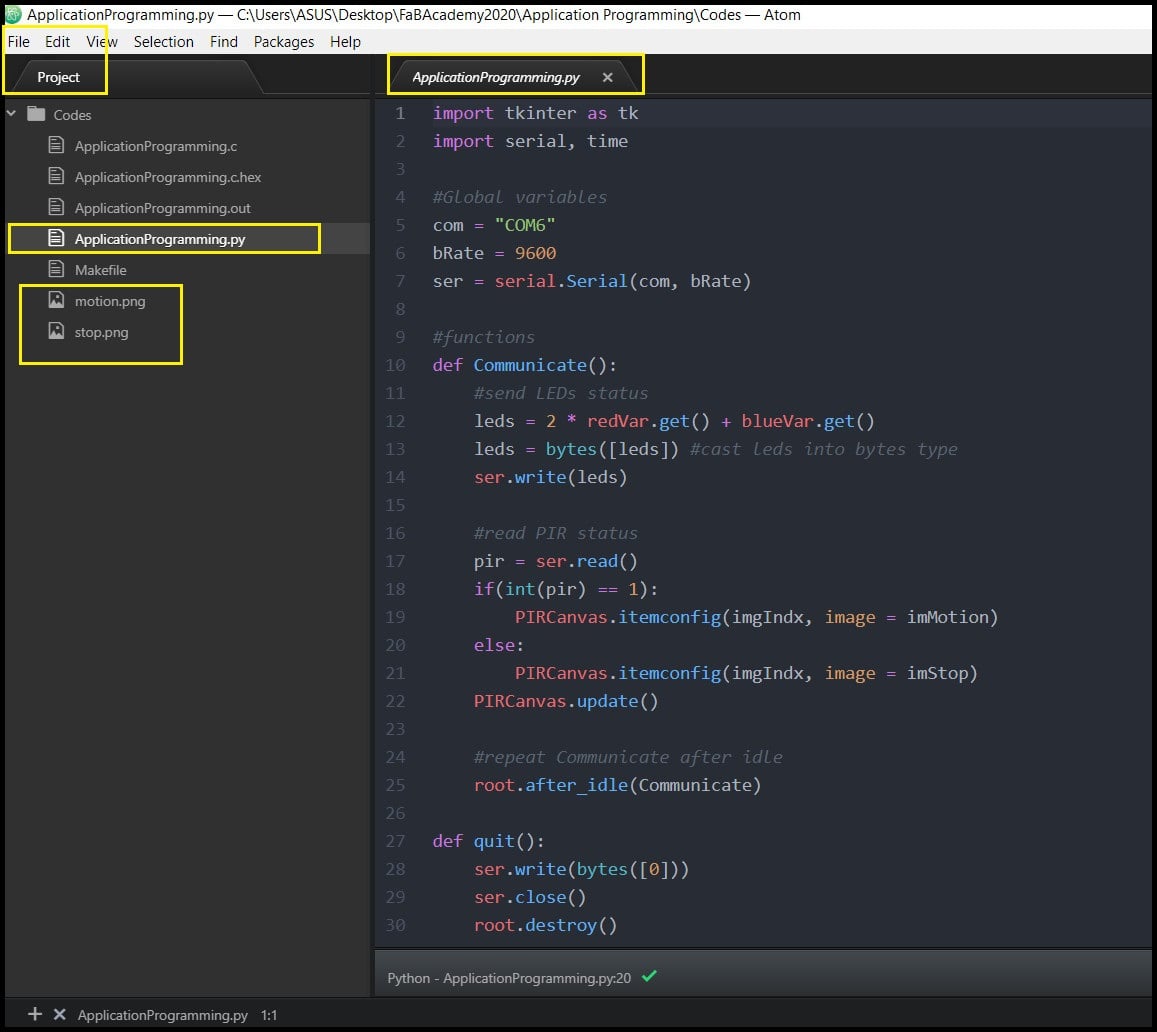
Make sure to connect the FTDI cable or Arduino UNO board before running the program using “Ctrl + Shift + B”.
Both the ATtiny44 Development Board and Python GUI are working in both directions, sending and receiving data serially. Each time communication happens, a single byte (8-bit) is sent or received.
The image should update as the PIR sensor status changes. And using the check buttons, LEDs on the ATtiny44 Development Board could be turned on or off.