8. Computer Controlled Machining
Group Assignment
Machine: ShopBot PRSalpha ATC 96-60-8
Software: VCarve Pro
File Downlaod
Test dxf File
LMT.ONSRUD MDF Cutting Data
LMT.ONSRUD MDF Cutting Tools Catalog
Safety First!: Safety cautions and procedures must be considered while working on Laser machines. Please read, understand and apply all caution signs.

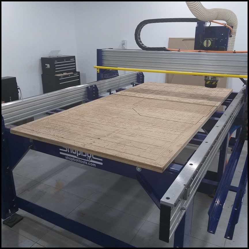
Machine Overview
The ShopBot PRSalpha ATC 96-60-8 is an affordable full-sized gantry tool for CNC cutting, drilling, carving and machining of wood, plastic, aluminum and other materials.
Specs:
Cut/Movement Area (Length x Width x Plunge): 105” x 61” x 8” (2.67m x 1.55m x .2m)
Step Resolution: 0.0004” (0.010mm)
Positional Repeatability: +/- 0.002” (0.051mm)
Spindle RPM: Max 18,000 RPM
XY Move Speed (with full cutting force): Max 360”/min (9.1m/min)
Z Move Speed (with full cutting force): Max 120”/min (3m/min)
Tooling
We visually inspected different types of endmills and used two of them to complete our tests. We inspected the spiral, v-carve, ball nose and tapered ball nose endmills. Each has designed for a specific purpose and all can be used in a CNC router.
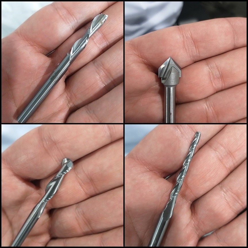
For the tests we used LMT.ONSRUD 57-287, a downcut spiral bit. It has two flutes and a center-cutting tip. Then we repeated the same test using LMT.ONSRUD 52-287 a similar upcut endmill. These endmills are designed for soft Wood, hard Wood, wood composite.

To minimize or eliminate runout (“Runout is the tendency to spin the tool around a centerpoint that is not the tool’s center. It makes the tool wobble instead of spinning cleanly and increases chip loads”), maximum part of endmill shank should be inserted to the collet. The end tip of endmill shank might flush with the collet and if possible it might go beyond the collet end. All ways, a clearance distance between the cutting edges and collet face should be maintained.

To tie the collet and endmill to the spindle, we used to supplied wrenches. A simple safety feature is provided in the machine that one of the wrenches is attached through a string to the “INTERLOCK DISENGAGED - ENGAGED” key. So whenever you need to use the wrench you have to remove the key and spindle cannot be started. Note that to fix the collet to the spindle the dust extractor should be removed first.

Feed Rate
We used the Cutting Data Recommendations provided by the tool manufacturer to calculate the feed rate (“Feed rate the speed at which the cutter engages the part and is typically measured in units/minute”). We used the data provided for MDF which is similar to plywood Recommendations.
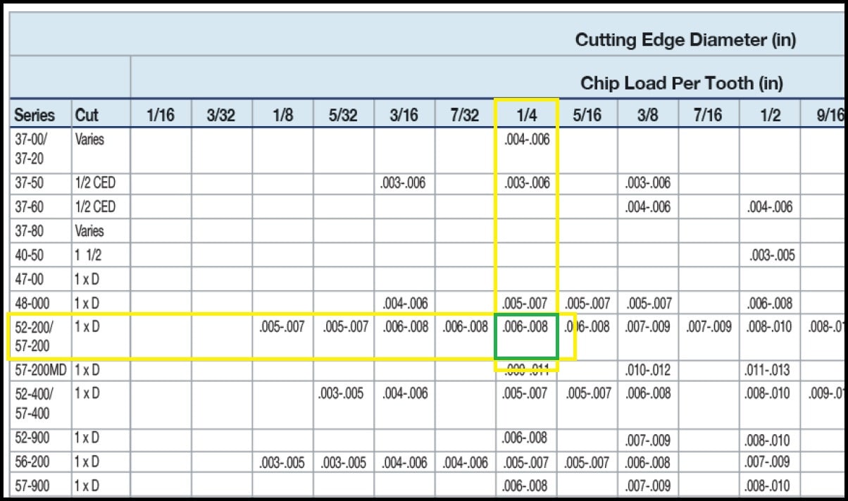
Downcut bit series: 57-200
Upcut bit series: 52-200
Bit diameter: 1/4”
Depth of cut: 1 x 1/4”
Using these inputs on the chart we find the recommended “Chip Load” is equal to 0.006”-0.008 inches/flue”. For this job we set the spindle speed to 14,000 RPM (max is 18,000 RPM).
Using the formula Chip Load = Feed Rate / (RPM x # of Flutes), where chip load in inches per flute, feed rate in inches per minute and RPM in revolution per minute, we can find that feed rate is equal to (168 - 224) inches/minute or (2.8 - 3.7) inches/second. Any value in the range would do fine.
Fixing The Work Piece
The machine has MDF sacrifice board fixed on bed. If the endmill penetrates the work piece the extra cut would happen on the sacrifice sheet. This way we make sure machine body and tool won’t be destroyed. Holes were drilled to work piece and wood screws used to fix it to sacrifice board. Note that when we work on software, we define “Boarder Gap” to be 30mm. Cutting will not be happening on this area, so we can use it to put the screws. On the other hand, if the work piece is misaligned to the machine axes, the boarder gap will compensate misalignment and cuts will be inside work piece.

Working on VCarve Pro
We used 17.0 mm latte sandwich uncovered wood to make the tests. Stock was measure using a caliper and the actual size was 17.2 mm. The actual size should be used in machine software. Step-by-step guide for working on VCarve Pro is provided in week assignment section.
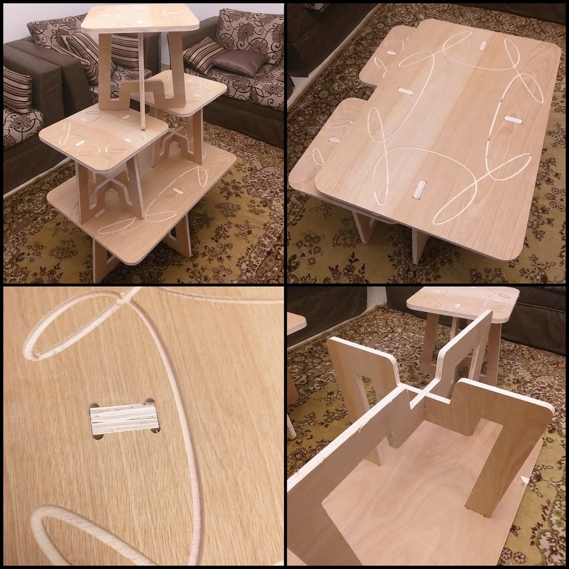
Hero Shoot!
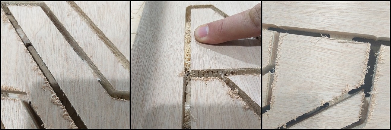
The first image compares the quality of cut on surface using downcut and upcut bits. Note that the chips appears attached to the surface (left) when using an upcut bit, while surface cuts appears better when using downcut bit (right).
In the second image chips are much remained between cuts when using a downcut bit. Also, a downcut bit generates more noise compared to an upcut bit.
The third image shows tabs (joints) between target cut and work piece. This will keep stock in place while performing the cuts.
Week Assignment
File Downlaod
Tables SolidWorks and dxf Files
Tables Nesting Inksacape File
Tables Nesting dxf File
Tables VCarvePro File
Tables VCarvePro Toolpaths File
The Design: Center and Side Tables
For this assignment, I designed center and side tables. I used SolidWorks and defined global variables for parametric design. There are two SolidWorks files. The first for the center table, and the second for side tables.
I used 17.0 mm plywood wood to make the tables. Stock was measure using a caliper and the actual size was 17.2 mm. The actual size should be used in design and machine software.

Each table is extruded from three sketches; one for the top and two for the support bases. Extrusion height is controlled by the global variable “Plywood”, which define wood board thickness.
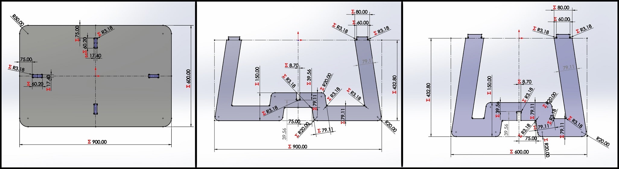
For corner reliefs I used dog-bones. The radius is a function of endmill diameter (0.25”), which define in the global variable “Bit”. Joint (used to assemble top to support bases) width and height are related to plywood thickness global variable “Plywood” and joint length “JointLength” global variable.

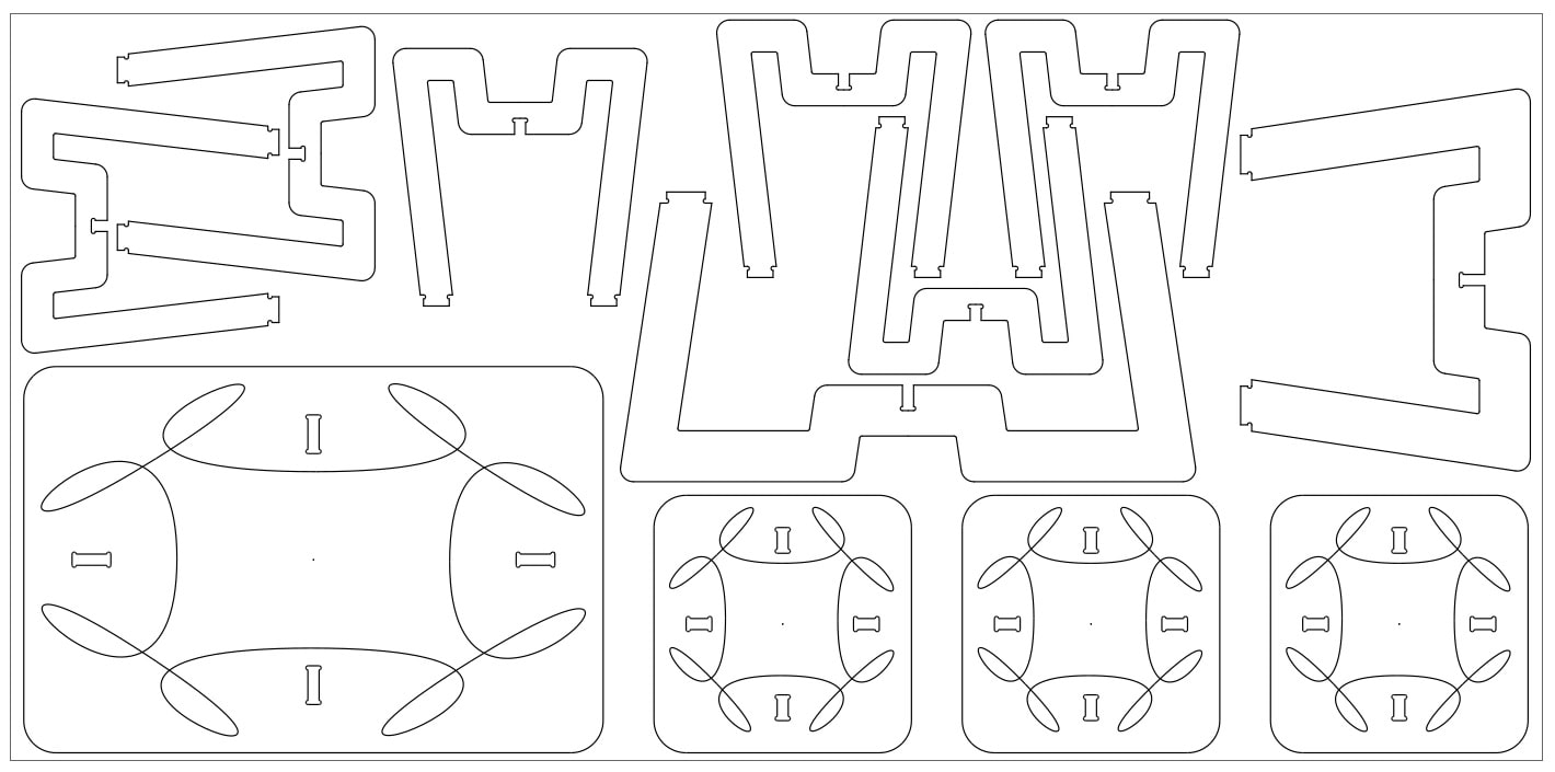
After completing the 3D model, I saved sketches as dxf files and imported them into Inkscape. I used Inkscape to add some engraving to table tops, and to find how many pieces a single 8ft x 4ft plywood board (2440mm x 1220mm) would fit. I drew a boarder assuming 30 mm boarder gap and made manual nesting. The board is enough to make one center table and 3 side tables. After completing working on Inkscape, I saved the file as dxf.
Working on VCarve Pro
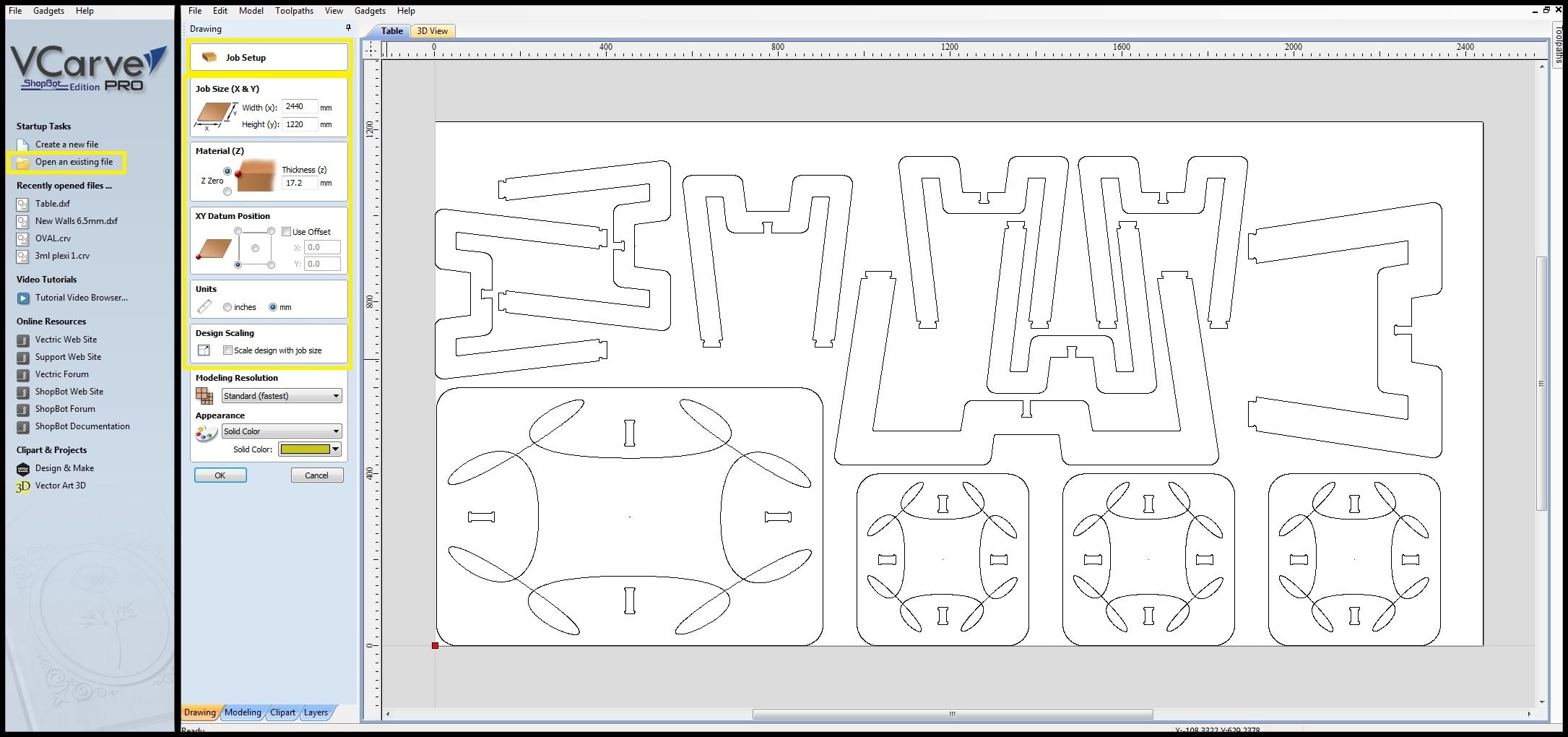
Step 1: Open VCarvePro and click on “Open an existing file”. Locate the Table.dxf file and open it. Dxf file will be displayed and “Job Setup” menu opens. Insert job settings and click “Ok”. The board I used is 2440mm x 1220mm and measured thickness is 17.2mm
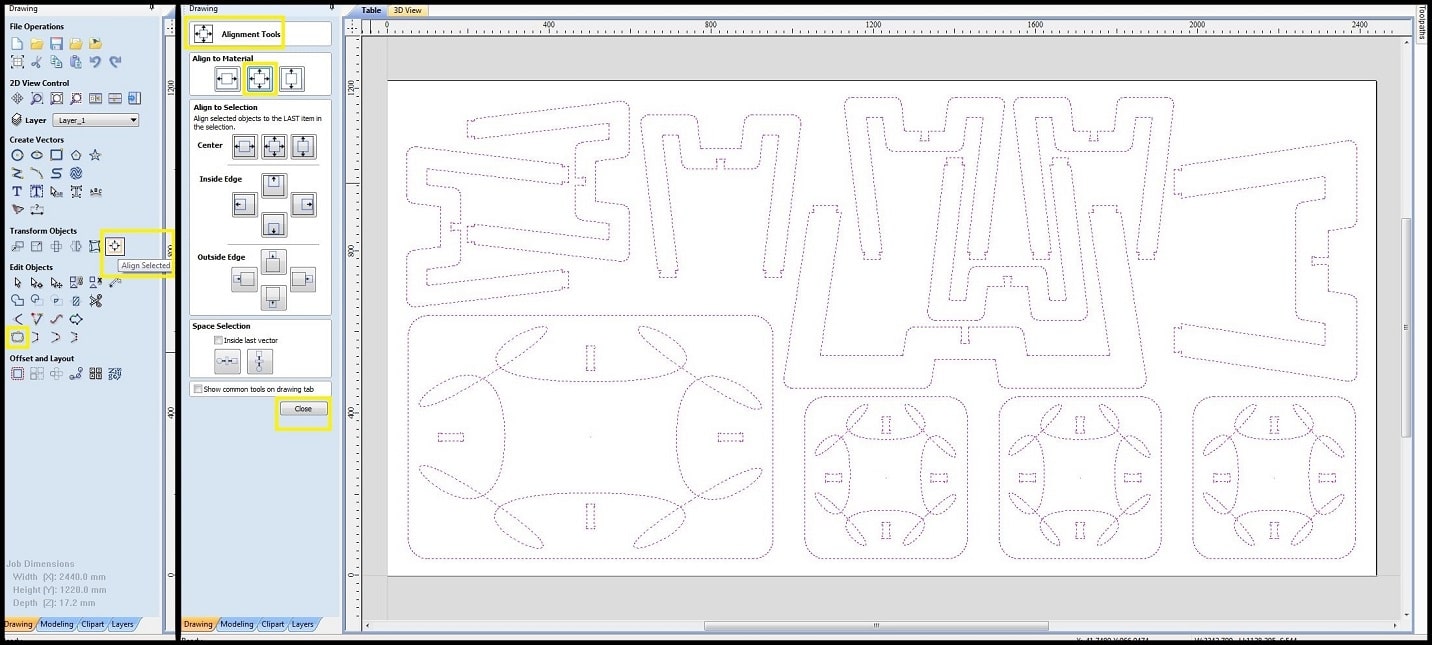
Step 2: Select all objects in the drawing and click on “Align Selected Objects”. “Align Tools” menu opens and in “Align to Material” select to center drawing to working board center. You can see there is a boarder gap around objects, which made in Inkscape file. Click “close”.
Step 3: While all objects selected, click on “Join - join open vectors”, This will join lines and curves in each object so is will be treated as a single toolpath.
Step 4: We need to temporary group objects that contain more than a toolpath, specifically the tops of center and side tables. Select top one by one and for each click on “Group - group selected objects”. This is needed if we will use nesting feature to make sure each object will be moved, rotated or aligned as a single block. After completing grouping, unselect all and click on “Nesting - nest selected objects”.

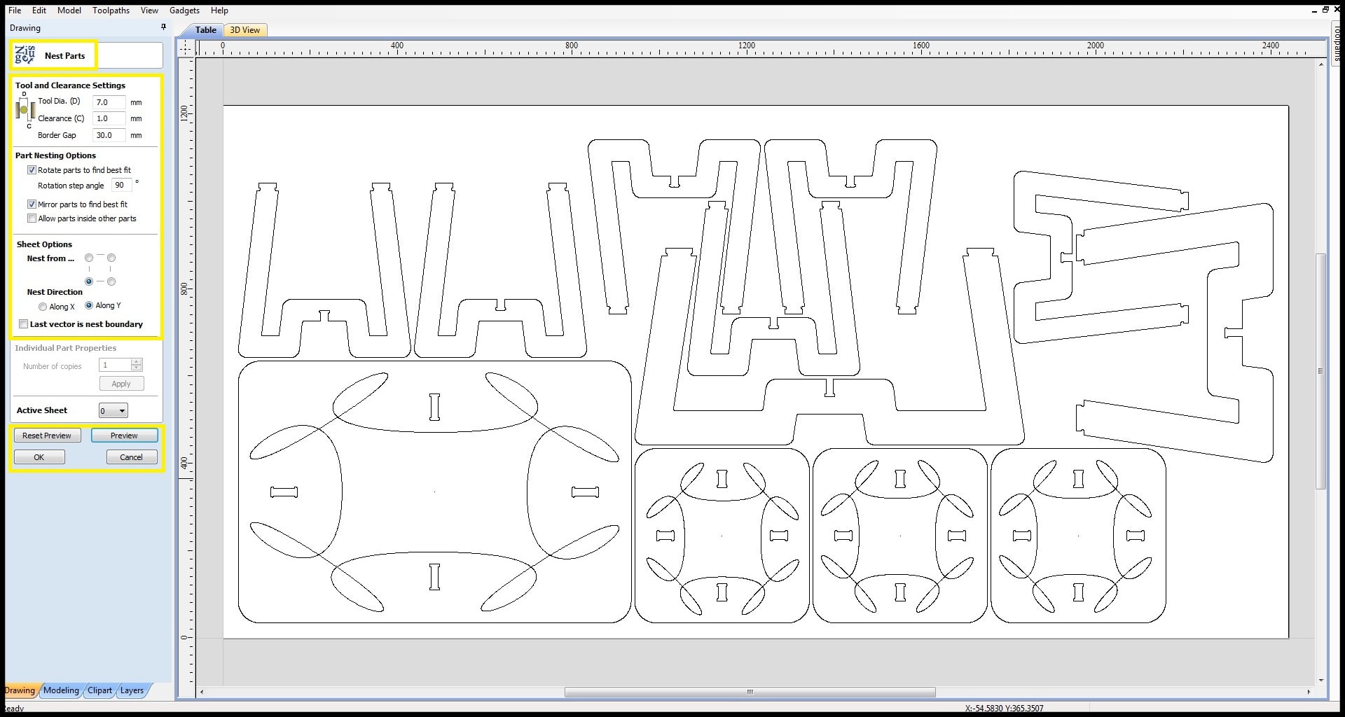
Step 5: In “Nest Parts” menu insert setting to be used. The value 7.0mm is the gap that will be maintained around object when the software runs the nesting command. 1.0 mm is the clearance around each gapped object. So the distance between objects will be 2 x ( 7.0 + 1.0) = 16.0 mm. Select all objects and the nesting command will run to distribute objects on board. Click on “Preview” and the result of nesting will be displayed.
Compare the result with manual nesting done in Inkscape. In this case, I use manual nesting because there are larger gaps between objects and it will easier to add tabs to keep objects in place while cutting. Click on “Reset Preview” and then “Cancel”.
Step 6: Ungroup tables tops to separate toolpaths. in the top-right corner, click “Toolpaths” tab and in “Material Setup” menu, click on “Set…”. Insert settings and click “Ok” to accept.

Step 7: In “Toolpath Operations” click on “Profile Toolpath”. In “Tool” menu, if the endmill is defined in too database click on “Select” and find “57-287” in list. Otherwise, you can click on “Edit” and define the endmill locally for this job. Note that you have to calculate the “Feed Rate” as described in group assignment. Set “Plunge Rate” approximately to 1/3 of feed rate.

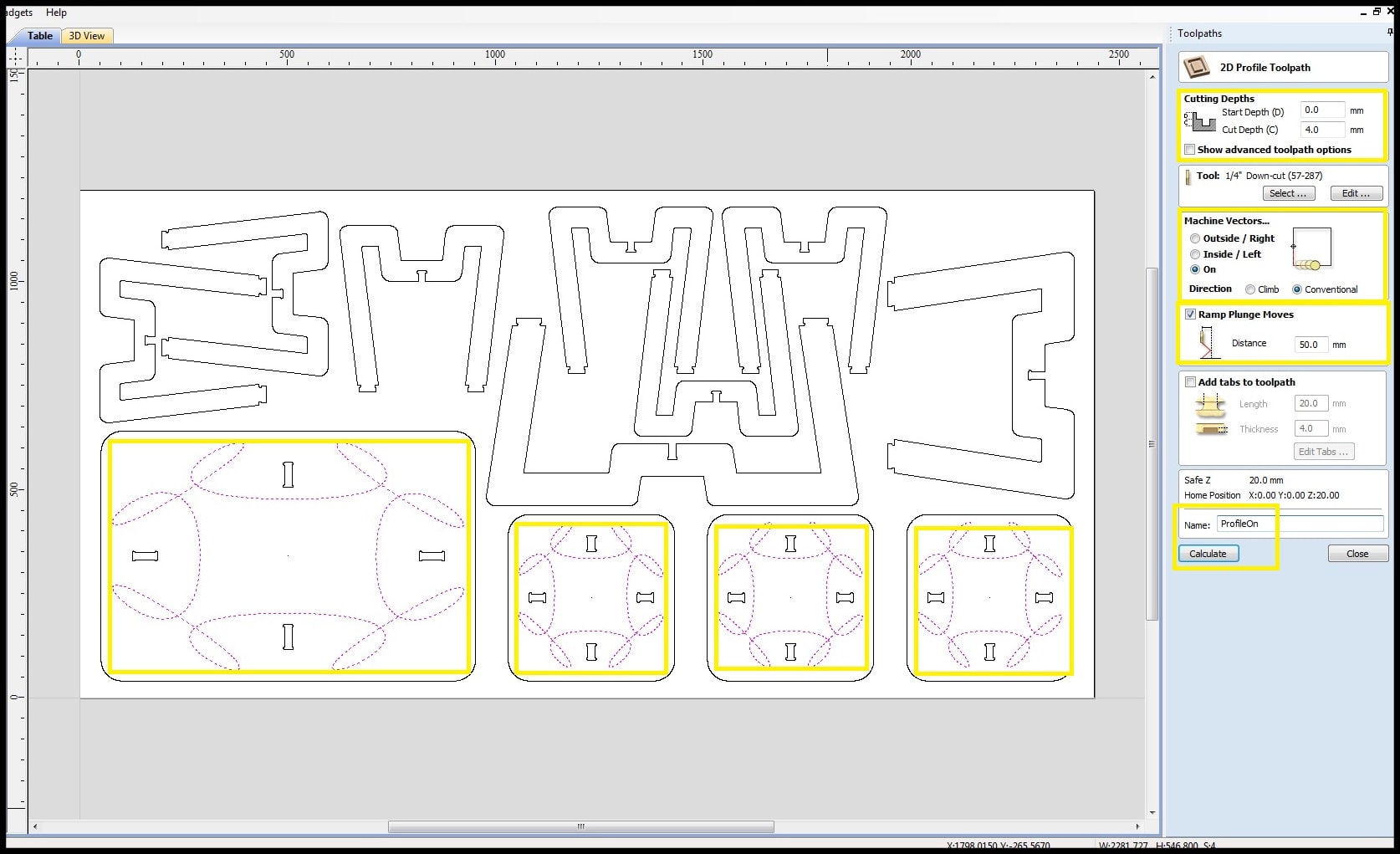
Step 8: First we will do the engraving paths on tables tops. In “Cutting Depths” menu set the depth to 4.0mm. This will be the depth of the engraving. In “Machine Vectors” menu, choose “On”. The endmill will move on the center of drawn line. For direction click “Conventional”. Enable “Ramp Plunge Moves” and set direction to 50.0mm. This will make endmill plunge gradually in X or Y direction. Rename the toolpath to “ProfileOn”. Shift and select engraving paths and click “Calculate”. A preview toolpaths opens where you can simulate the engraving operation. Click on “Close”.
Step 9: Now we will do the joints. In “Toolpath Operations” click on “Pocket Toolpath”. Make sure the right endmill is used. In “Cutting Depths” menu set the depth to 17.5mm. This will make the tool penetrates board thickness and touches the sacrifice board. Complete the other setting and rename the toolpath to “ProfilePocket”. Click on “Table” tab, shift select all joints and click on “Calculate”. For the warning message click “OK”. Click “Close” the preview and click “Table” tab.

Step 10: In “Toolpath Operations” click on “Profile Toolpath”. Make sure the right endmill is used. In “Cutting Depths” menu set the depth to 17.5mm. In “Machine Vectors” menu, choose “Out”. The endmill will cut outside the lines. Complete the other settings and rename the toolpath to “ProfileOut”.
We need to add tabs between objects and board so each part will be kept in place while cutting. First, shift select paths where cuts should be done. Enable “Add tabs to toolpath” and click on “Edit tabs…”. In tabs menu, select “Constant distance between tabs” and change as shown. Click on “Add tabs”. Review tabs and move away from curves using mouse. You can also delete tabs if it was necessary. Click “Close”. Change the “Length” and “Thickness” of tabs and click “Calculate”. Click “Yes” for the warning message.

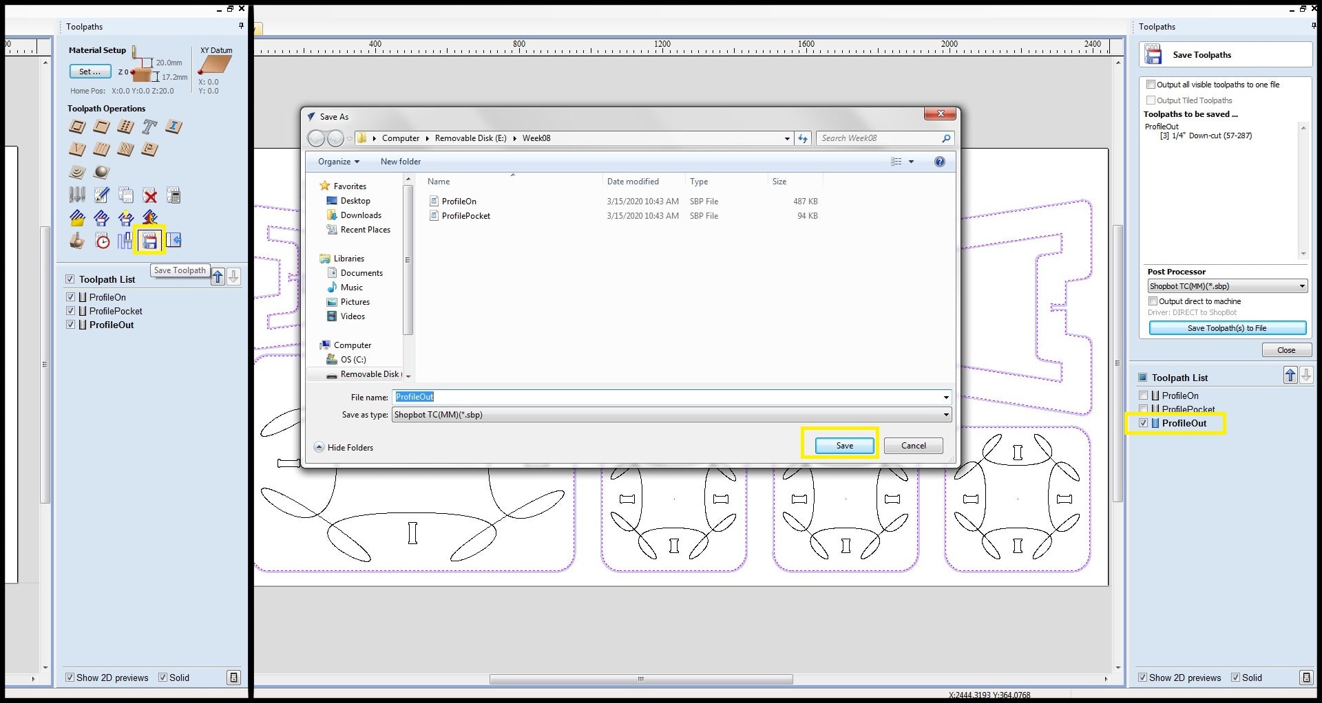
Step 11: Now we have all toolpaths define. First we need to save toolpaths. I chose to save toolpaths as separate file to run then on machine one by one. Check and highlight the first toolpath and click on “Save Toolpath”. Repeat for all toolpaths.
Step 12: Screw the board to the sacrifice board on the machine as described in group assignment. Start the ShopBot “Command Console”. If the message “STOP Button is ON” appears, press the “RESET” button in control box and then click “Ok” for the message.

Step 13: The X and Y axes should be referenced before using the machine. Click on “XY” in “Position” and the head will move and find reference using hardware proximity switches.
If you want to define your home position, click on “KeyPad” and move X and Y using arrows. When you are happy, click on “Zero Axes” and check “X-Axis” and “Y-Axis” and then click “ZERO”. Location should display zero for both X and Y.

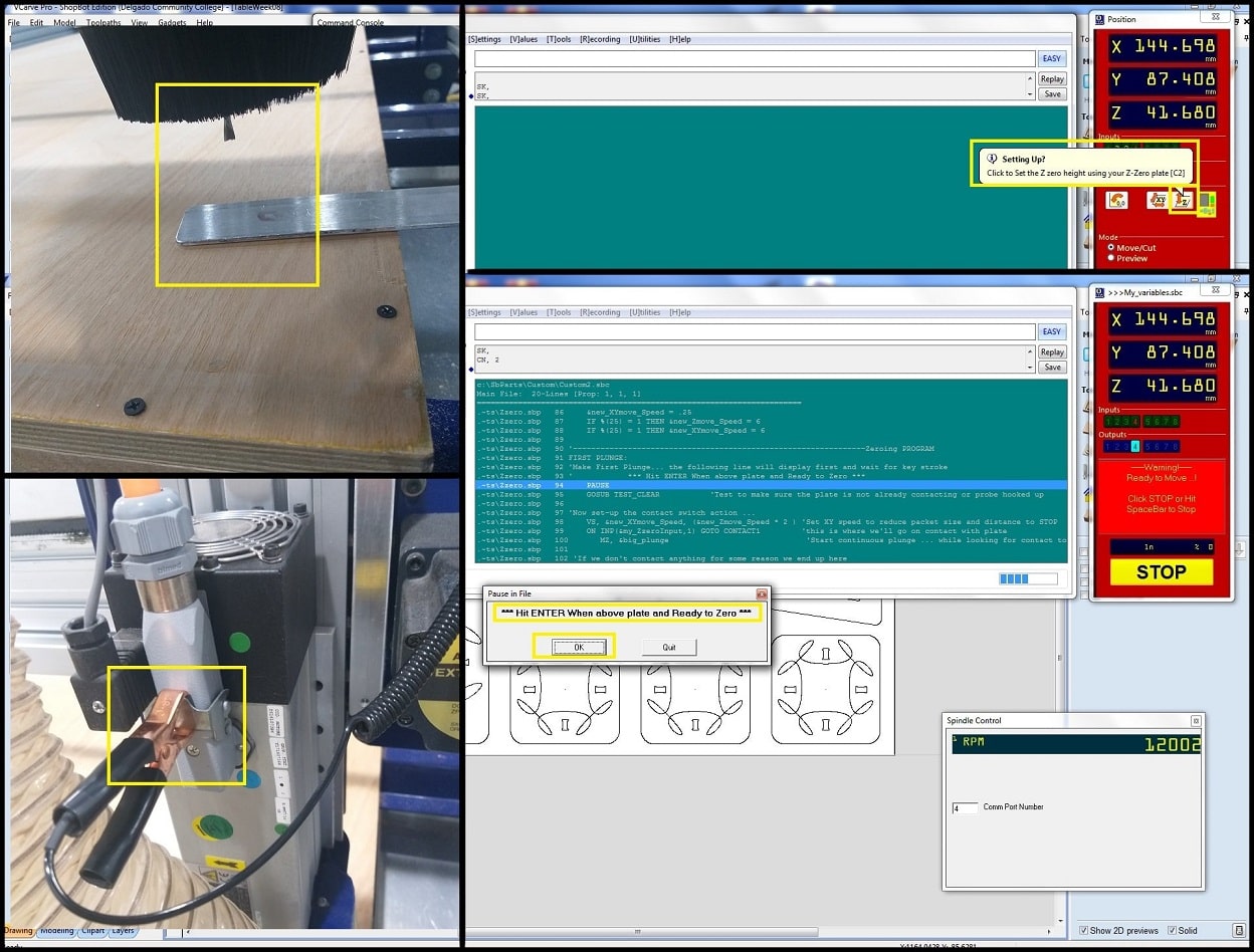
Step 14: After fixing the endmill and collet to spindle, Z-Axis should be zeroed. Move X and Y if necessary and put the “Plate” under the tool tip and keep a distance of 10-15mm. Move Z using KeyPad if needed. Connect the “Alligator Clip” to machine body. Click on “Z” in “Position” and the program will start a code to zero Z-Axis. Click “Ok” for the message asking to put the plate under the tool. When completed a confirmation message will appear. Click “OK”.
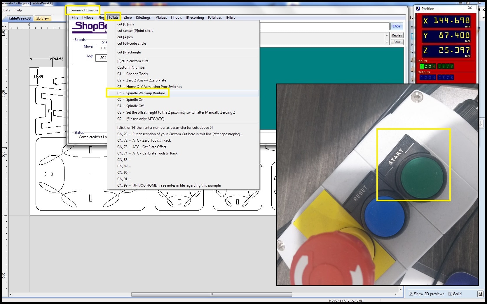
Step 15: If the machine was stop for some time, it is recommended to perform “Spindle Warmup Routine”. In ShopBot “Command Console”, open “Cuts” menu and select “Spindle Warmup Routine”. This step will take 9 minutes. When completed, spindle can be started using the “START” button in control box.
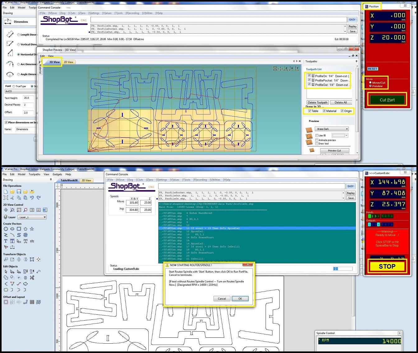
Step 16: In “Position” choose mode; “Preview” to check your toolpath or “Move/Cut” to start actual machine cutting. Click on “Cut Part” and select toolpath(s) to preview or cut. For actual machine cutting the machine will ask to start the spindle. If spindle already started, click “Ok” and machine will start working as per selected toolpath. Remember to start the dust extractor.
When the machine starts working, you cannot move the mouse pointer away from the “Stop” button. This is a safety feature. Machine could be stopped also using the space bar in keyboard or machine emergency button. The job took 55 minutes to complete.
Step 17: To remove tabs, I used wood chisel and fine wood file. I found that tabs I used were too big and 10mm x 2mm tabs would do good and would be removed easily.
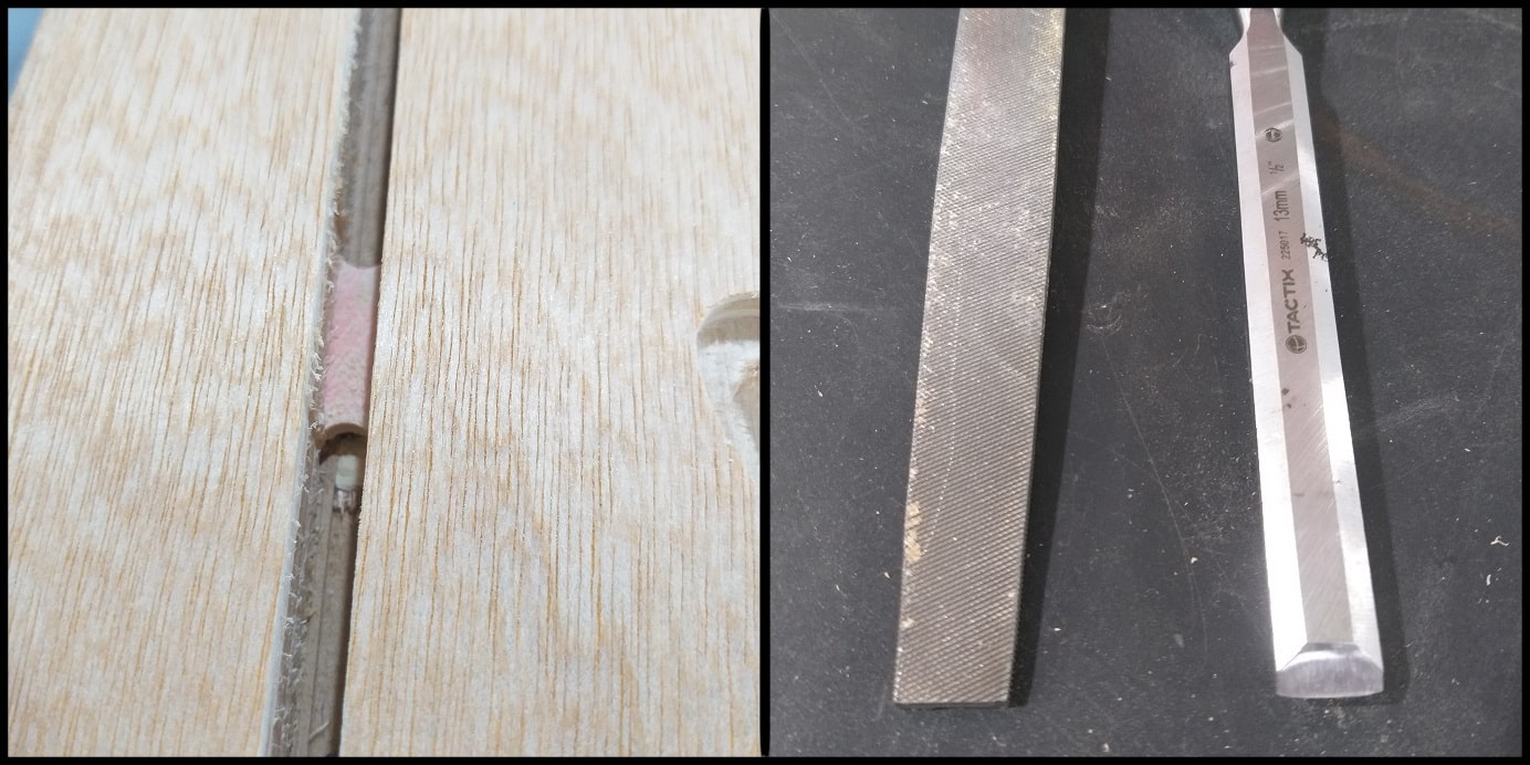
Step 18: Due to differences in board thickness in X and Y direction, sanding may be needed to fit joints. Also, using a downcut bit would leave chips attached to cutting edge on the lower surface of the board. Using smooth filing would remove those chips.
Image below shows part of objects nesting and a sample of the three toolpaths (on engraving, pocketing, out cut).

Problems and Fixes
In this design I used (20 mm x 4 mm) tabs. It was difficult to remove them from the final cuts. Next time, I would use smaller tabs, something like (10 mm x 2 mm) or (5 mm x 2 mm).
Hero Shoot!