1. Principles and Practices
In this part I will describe the impact of my final project, as well as concept of operation and block diagram.
Justification
Every year in Jordan tens of people found dead because of Carbon Monoxide Poisoning (COP).1, 2, 3
“COP is a common occurrence in today’s society, one of the most common poisonings worldwide, and is responsible for more fatalities than other toxic agent.”4
COP has a mechanism of action on blood. “Red blood cells pick up Carbon Monoxide (CO) quicker than they pick up oxygen. If there is a lot of CO in the air, the body may replace oxygen in blood with CO. This blocks oxygen from getting into the body, which can damage tissues and result in death. CO can also combine with proteins in tissues, destroying the tissues and causing injury and death.”5
“Carbon monoxide has been termed the “silent killer” due its physical characters as well as its mechanism of action.”4
For economic reasons and lack of resources, the use of conventional heating systems indoor will continue putting many in risk of death or serious health conditions. In addition, many people tend to stop exhaust fans to keep warm air inside. A preventive monitoring system installed indoor will result in reducing the risk of COP and will provide early alarm and/or actions to replace air inside.
Carbon Monoxide Monitoring System (COMS)
COMS will measure CO levels in air inside and produce necessary action to inform people about potential risks. Also will communicate with exhaust fan units to operate and replace air inside.
The system consists of two main components; CO Monitoring Unit and Exhaust Fan Control Unit.
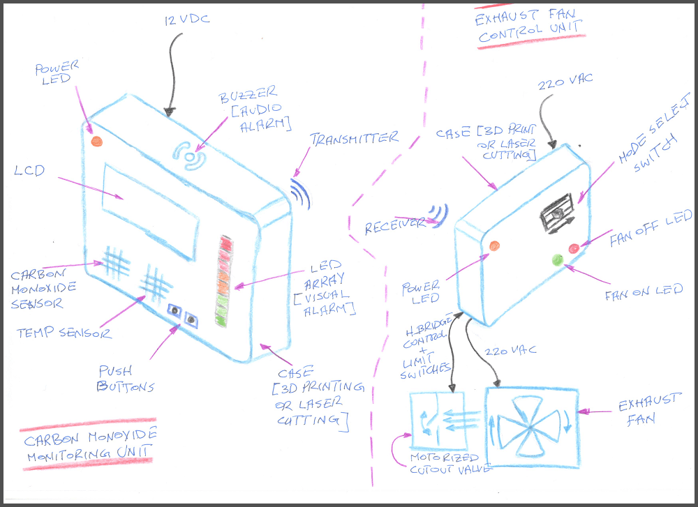
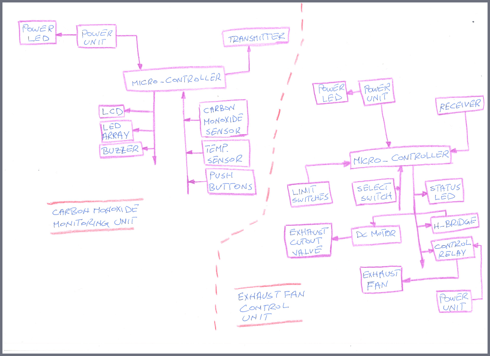
CO Monitoring Unit (COMU)
The COMU consists of the following:
Control unit
Micro-controller: analyzes data from input devices and takes the necessary actions and displays correct messages.
Input devices
CO sensor: measures CO level in air.
Temperature sensor (Optional): measures temperature inside.
Push buttons: the interface through which user control the system.
Output devices
LCD: displays CO level, temperature and correct messages.
LED array (green-to-red): displays CO level (visual alarm).
Buzzer: activated at high CO levels (audio alarm).
Transmitter: communicates with exhaust fan control unit.
LED (orange): shows if unit is connected to power.
Exhaust Fan Control Unit (EFCU)
The EFCU consists of the following:
Control devices
Micro-controller: analyzes data from input devices and takes the necessary actions.
Input devices
Receiver: receives a signal from COMU and turns exhaust fan ON/OFF and opens/closes exhaust fan cutout valve accordingly.
Toggle switch: controls the mode of operation of the exhaust fan (OFF/ON/COMS Control)
Limit switches: control the limits of exhaust cutout valve.
Output devices
Control relay: controls the exhaust fan.
H-bridge and DC motor: open/close exhaust cutout valve.
LED (green/red): shows the status of exhaust fan.
LED (orange): shows if unit is connected to power.
COMS Concept Sketch
COMS Block Diagram
Research and References
1: Carbon monoxide poisoning reason behind Madaba couple’s death
2: Four Yemenis ‘died of carbon monoxide poisoning
3: Man dies of carbon monoxide poisoning
4: Trends of carbon monoxide fatalities in Jordan
5: Carbon Monoxide Poisoning