4. Schematics and PCBs
4.1. File Download
COM Eagle files
COM PNG files
EFC Eagle files
EFC PNG files
The CO_SAFE has two circuit boards, the first for Carbon Monoxide Monitoring unit (COM) and the second for Exhaust Fan Control unit (EFC).
4.2. Carbon Monoxide Monitoring Unit (COM)
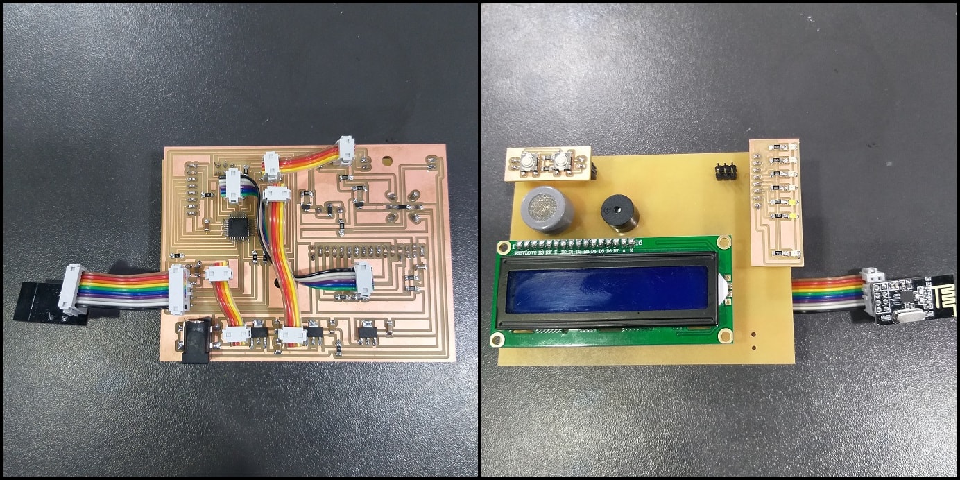
The COM is the main board in system where measuring happens and alarms and actions are taken accordingly.
The power block contains input 2.1mm jack supplied with 12 VDC. There are three regulators in the power block. 3.3 VDC to power the wireless module (cable with 1x2 headers), 5 VDC to power the ATmega328 (cable with 1x2 headers) and 5 VDC to supply other components like the buzzer, LCD and CO sensor.
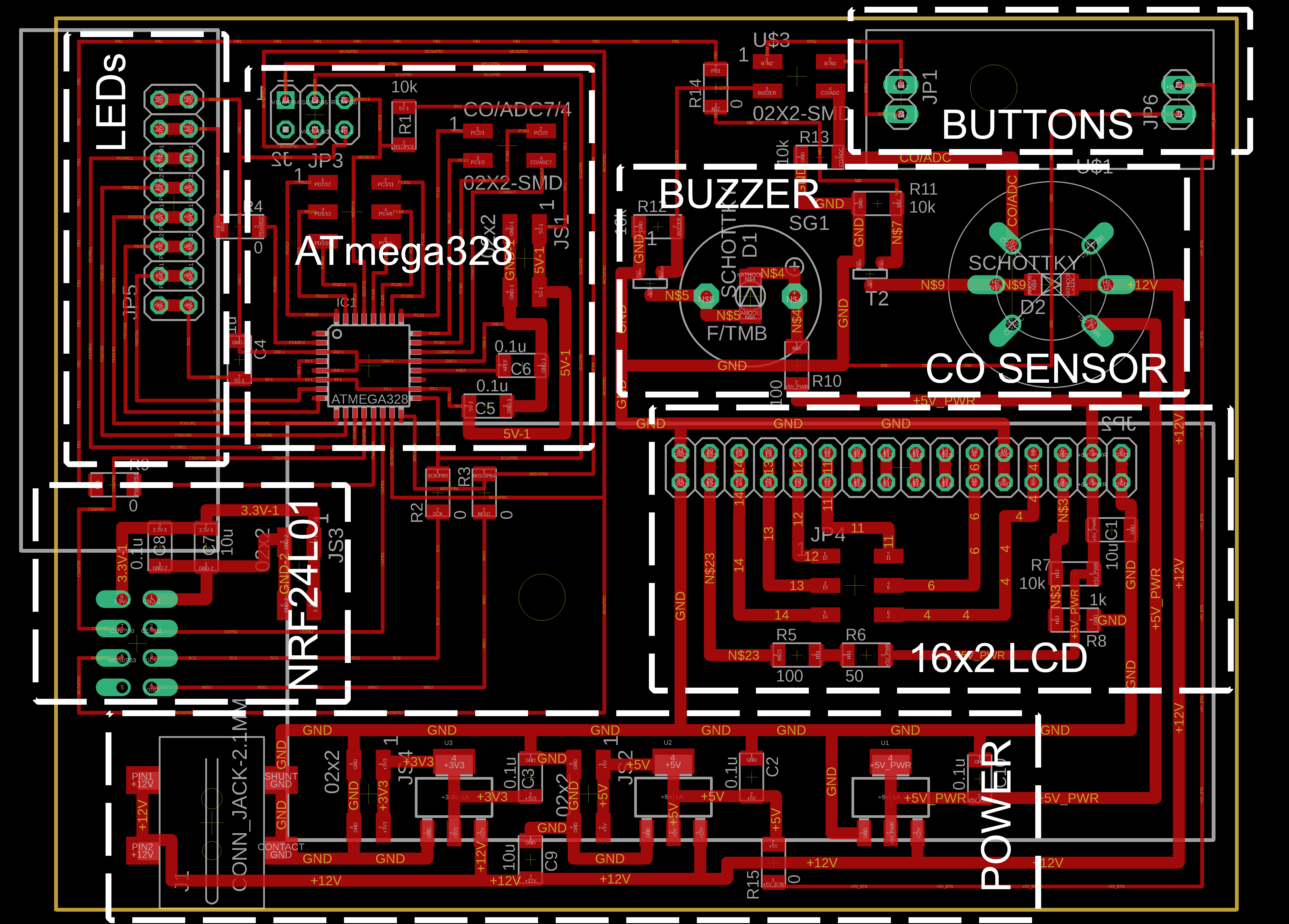
Other cables are used to connect the ATmega328 to components. For LCD, a cable with 2x3 headers is used, for buttons a cable with 2x2 headers is used and for the wireless module a cable with 2x4 headers is used.
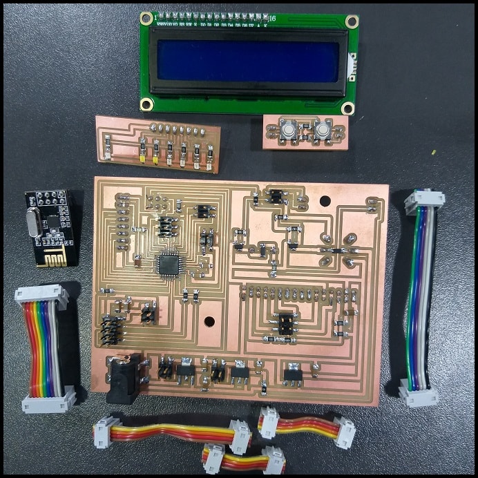
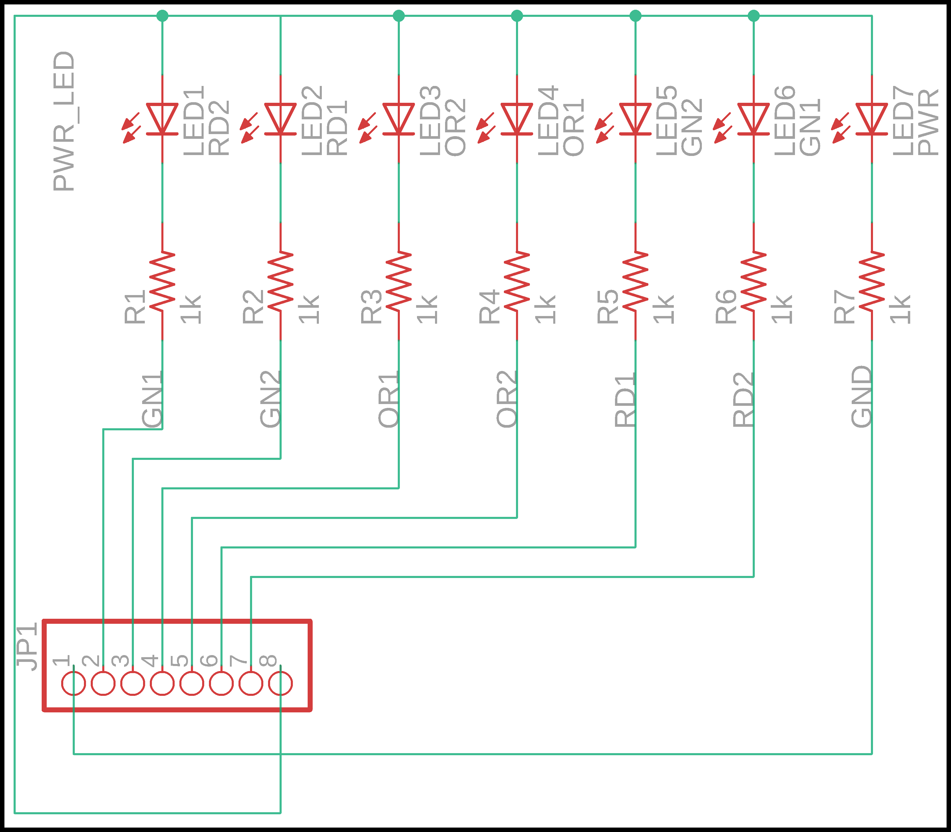
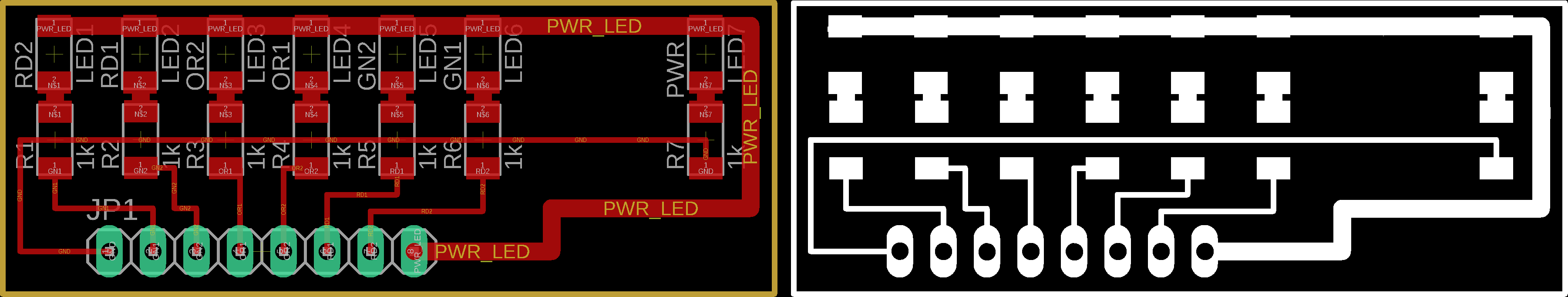
A modules was designed for LEDs having a power on LED and 6 visual alarm LEDs (2xWhite, 2xOrange, 2xRed)
And another modules was designed with 2 push buttons to control settings and function of the COM.
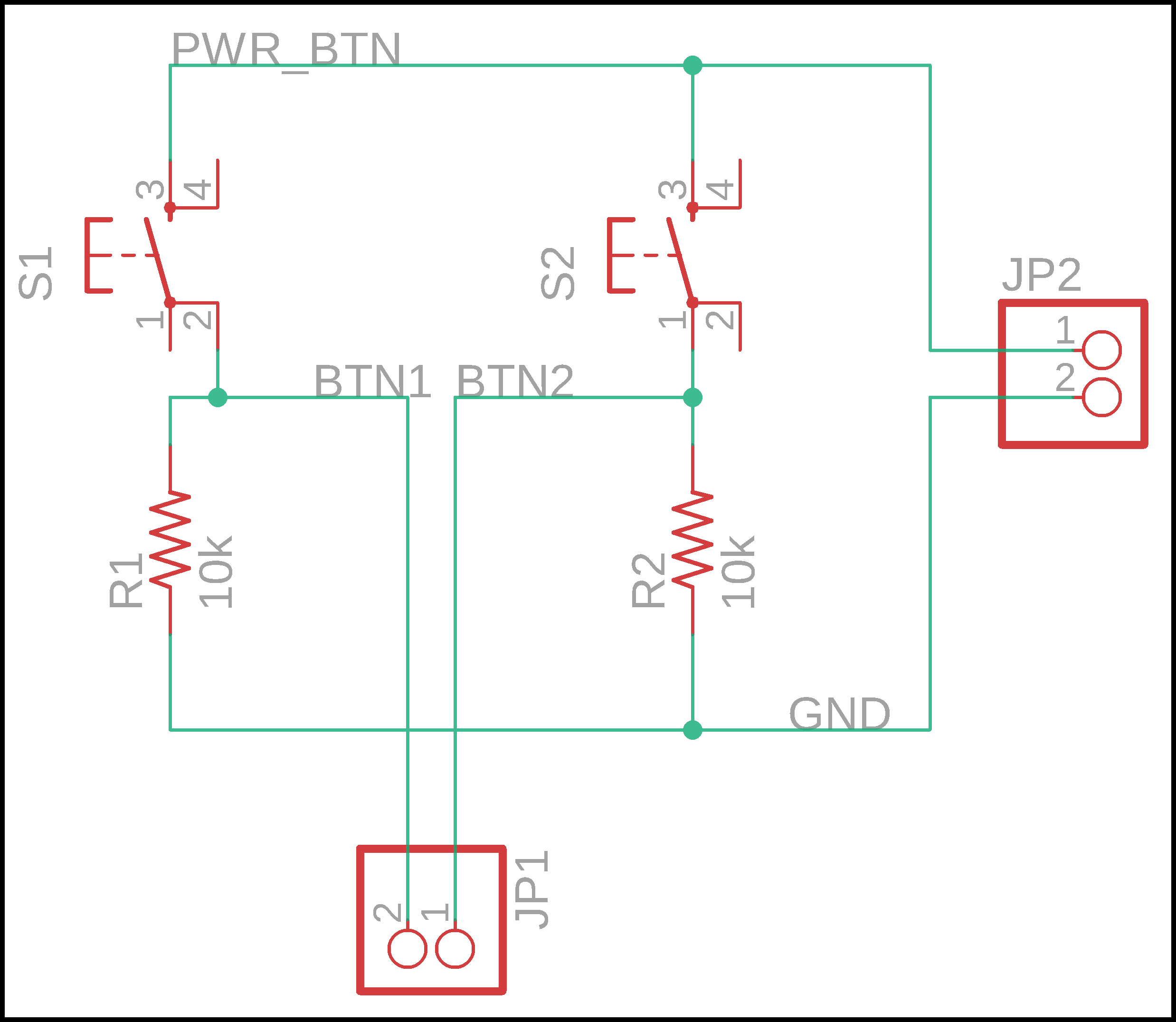
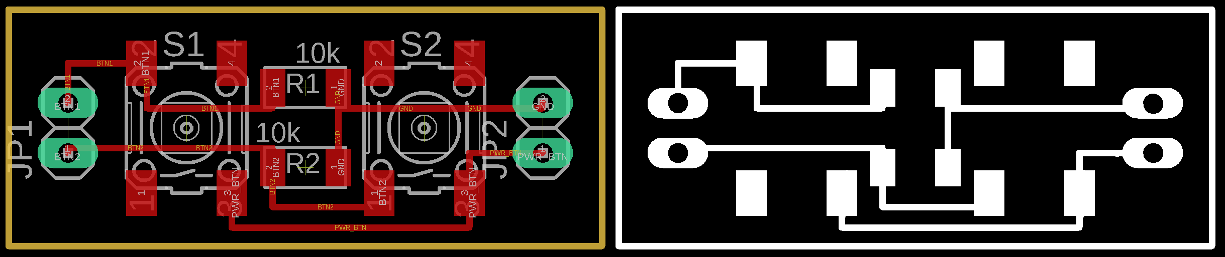
Both module are connected to the main board (in addition to LCD) using male-female headers. The CO sensor and buzzer both were soldered to board.
4.3. Exhaust Fan Control Unit (EFC)
The EFC receives a command signal from the main board (COM) to turn the exhaust fan on or off.
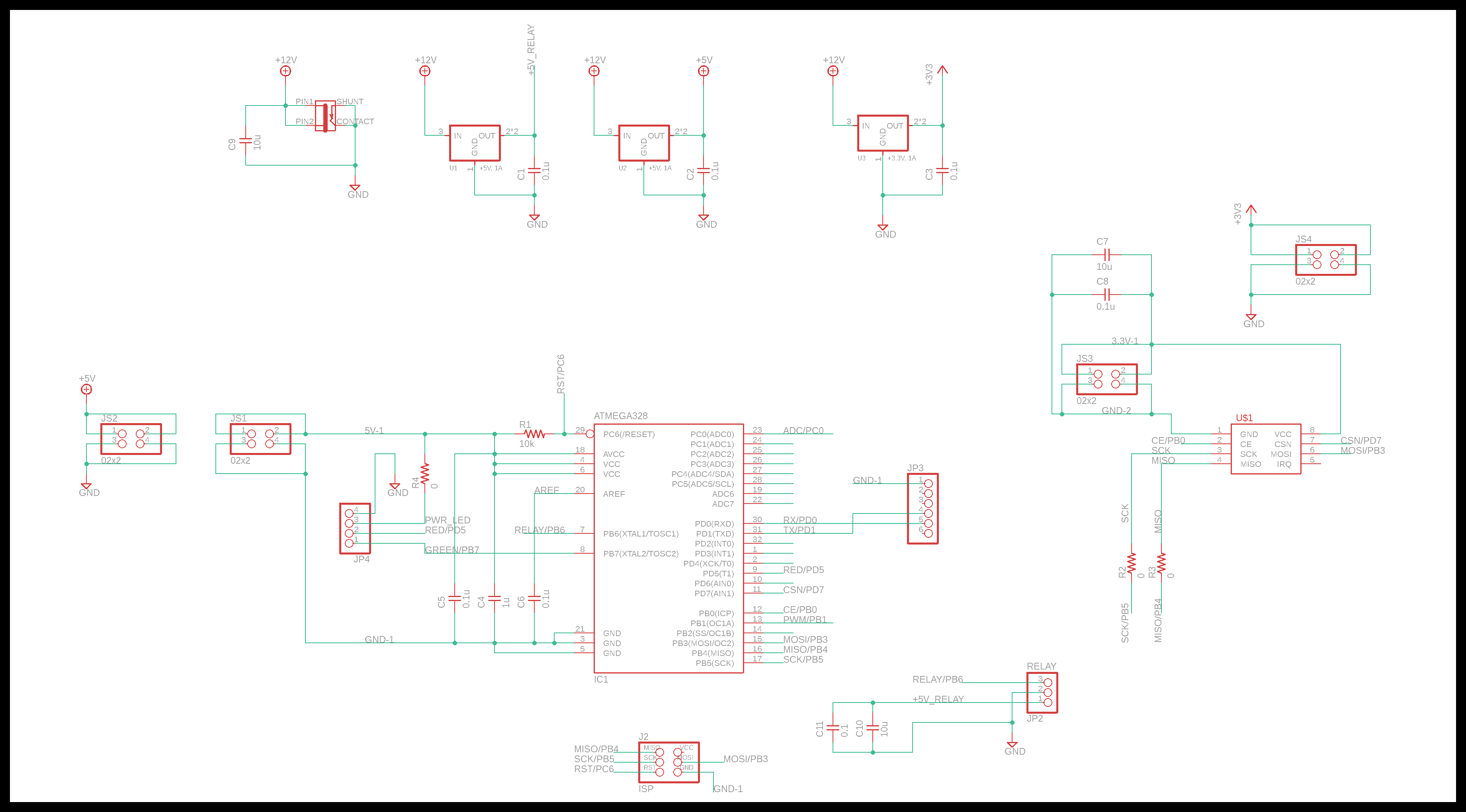
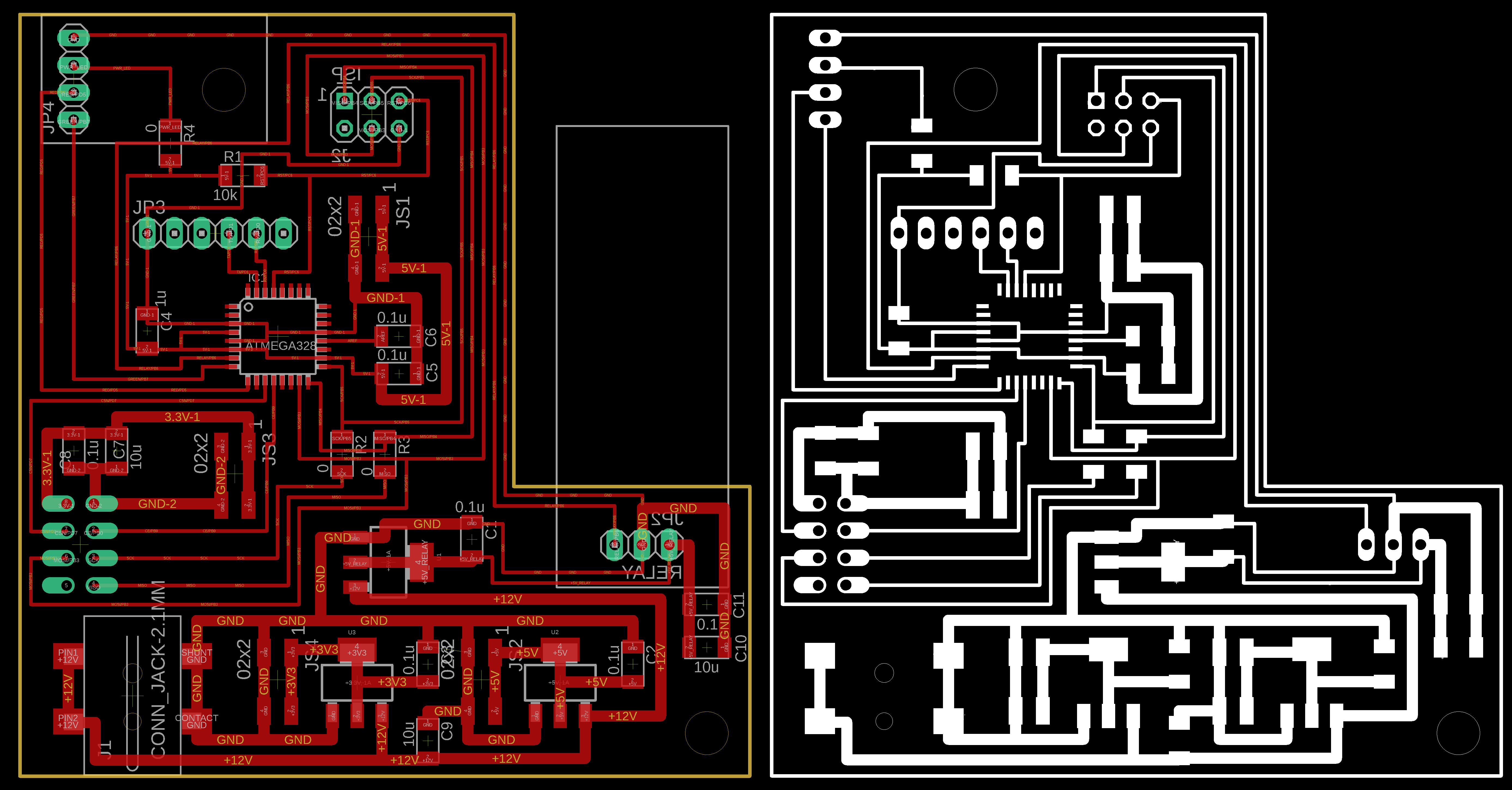
The power block contains input 2.1mm jack supplied with 12 VDC. There are three regulators in the power block. 3.3 VDC to power the wireless module (cable with 1x2 headers), 5 VDC to power the ATmega328 (cable with 1x2 headers) and 5 VDC to supply the relay module.
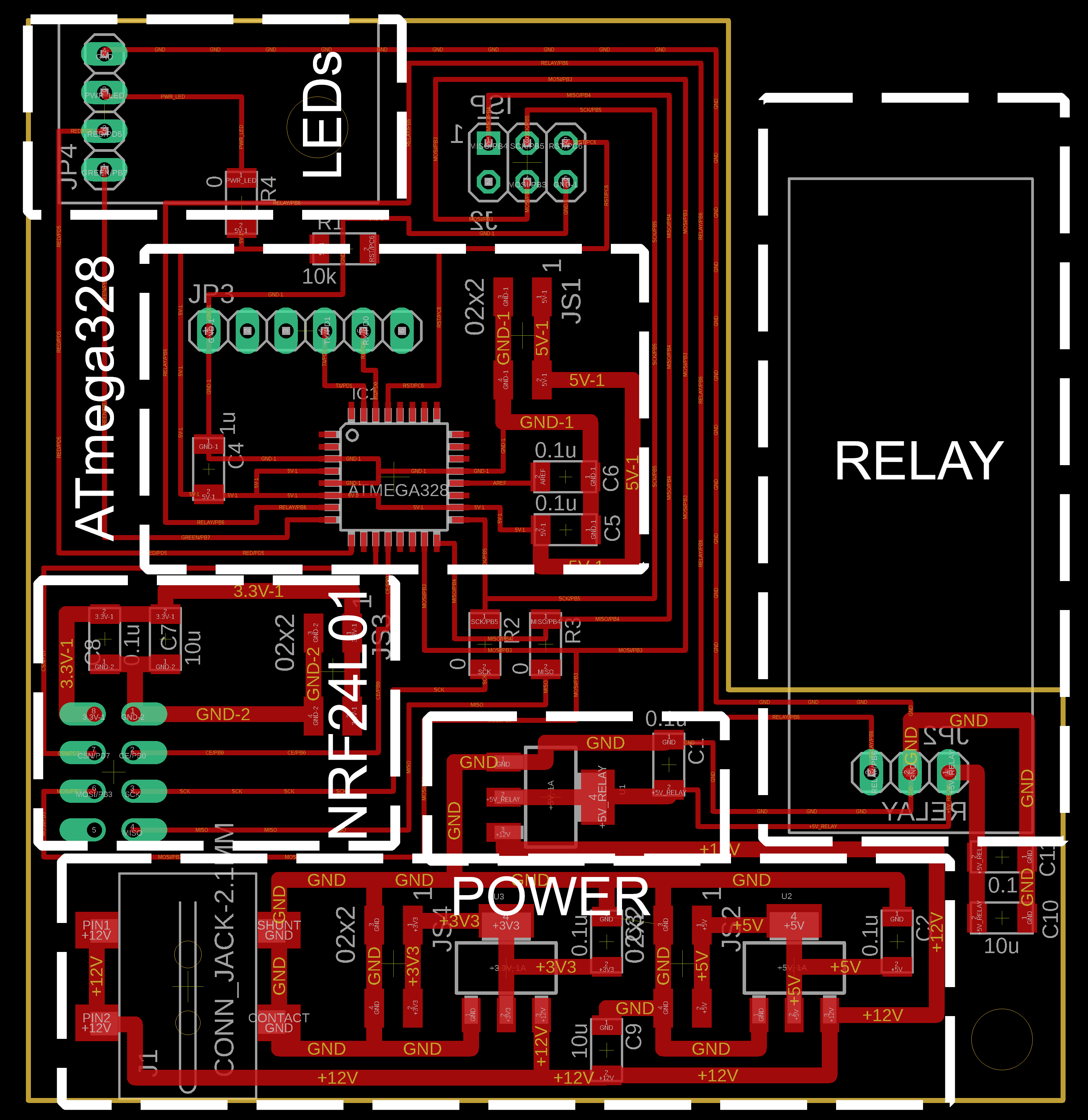
A cable with 2x4 headers is used to connect the wireless module to the ATmega328 signals, and another cable with 1x3 headers to connect the relay module to the board.
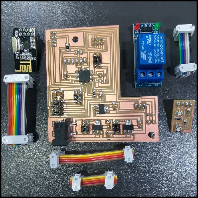
A modules was designed for LEDs having a power on LED and 1 RGB LED to show to fan state (green = on, red = off).
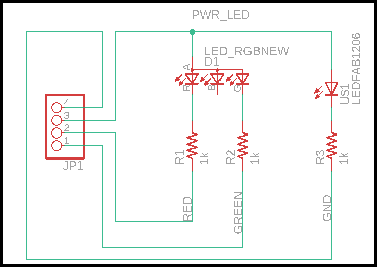
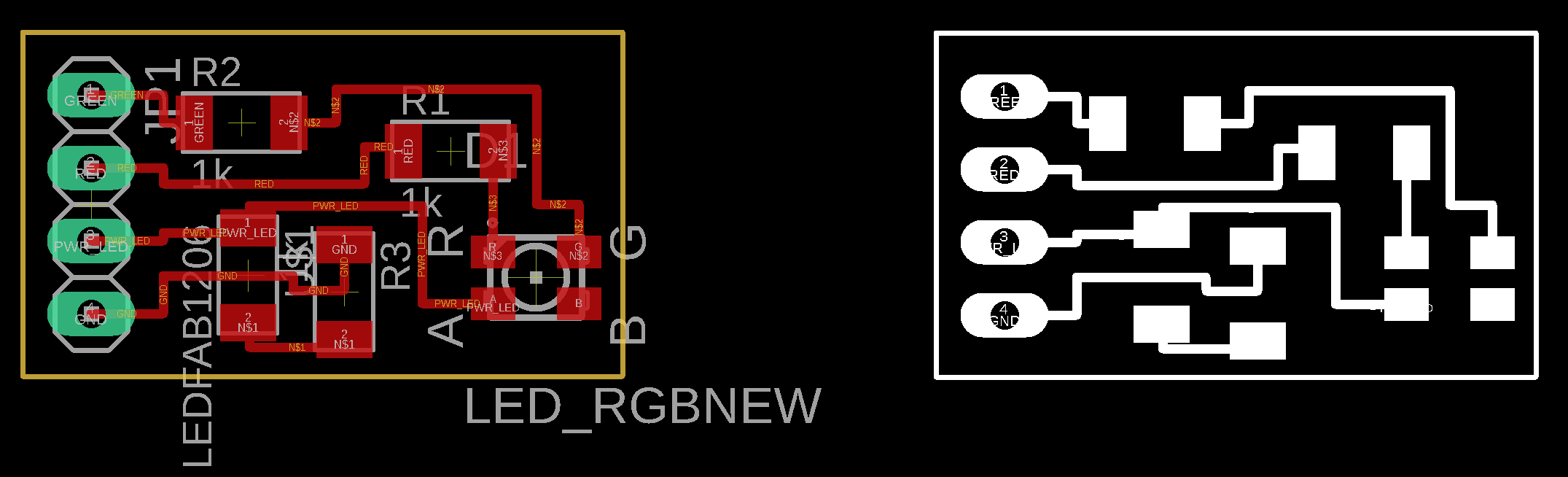
The module is connected to the main board using male-female header. The relay module is soldered to board.