15. Networking and Communications
Group Assignment
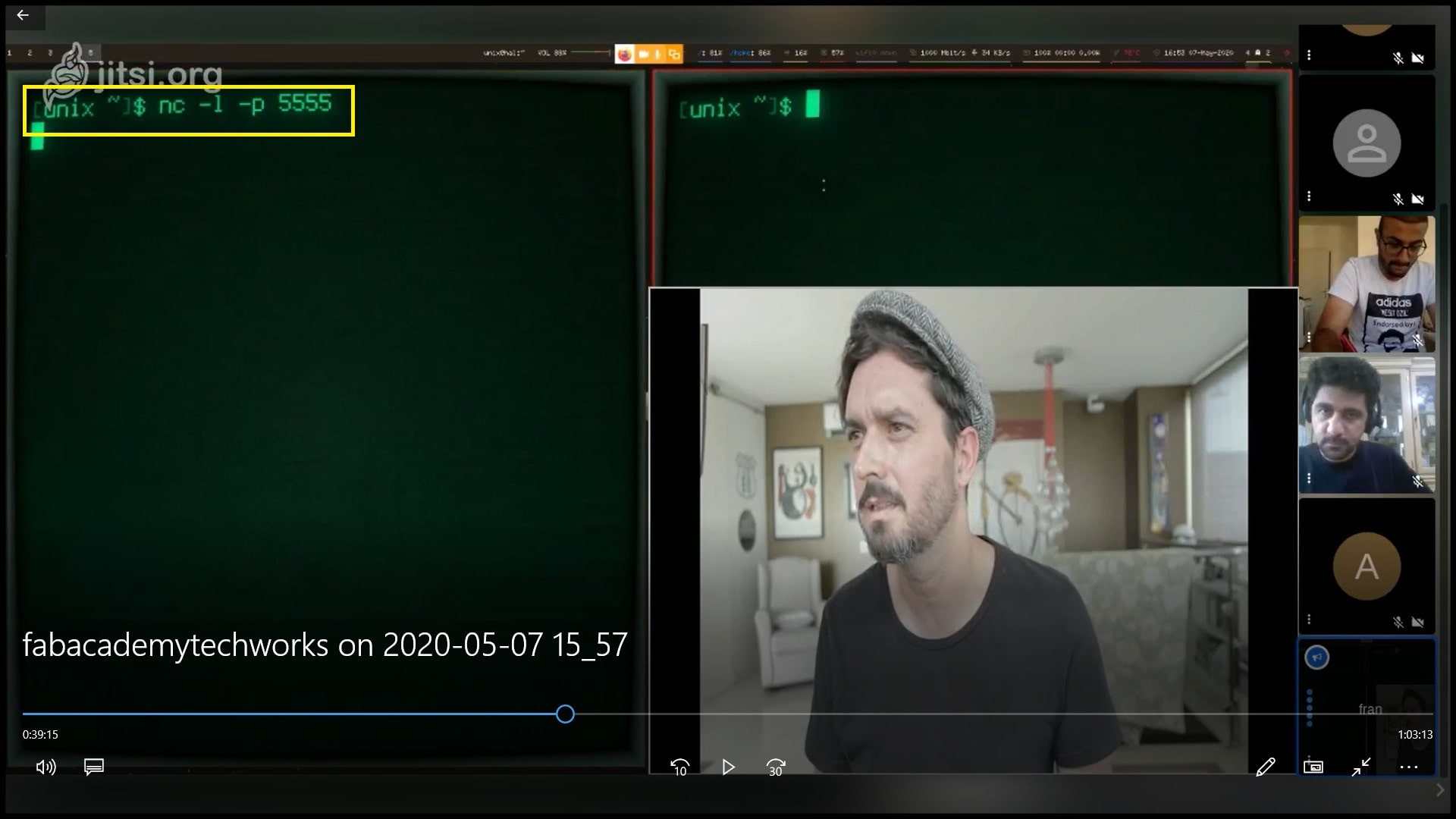
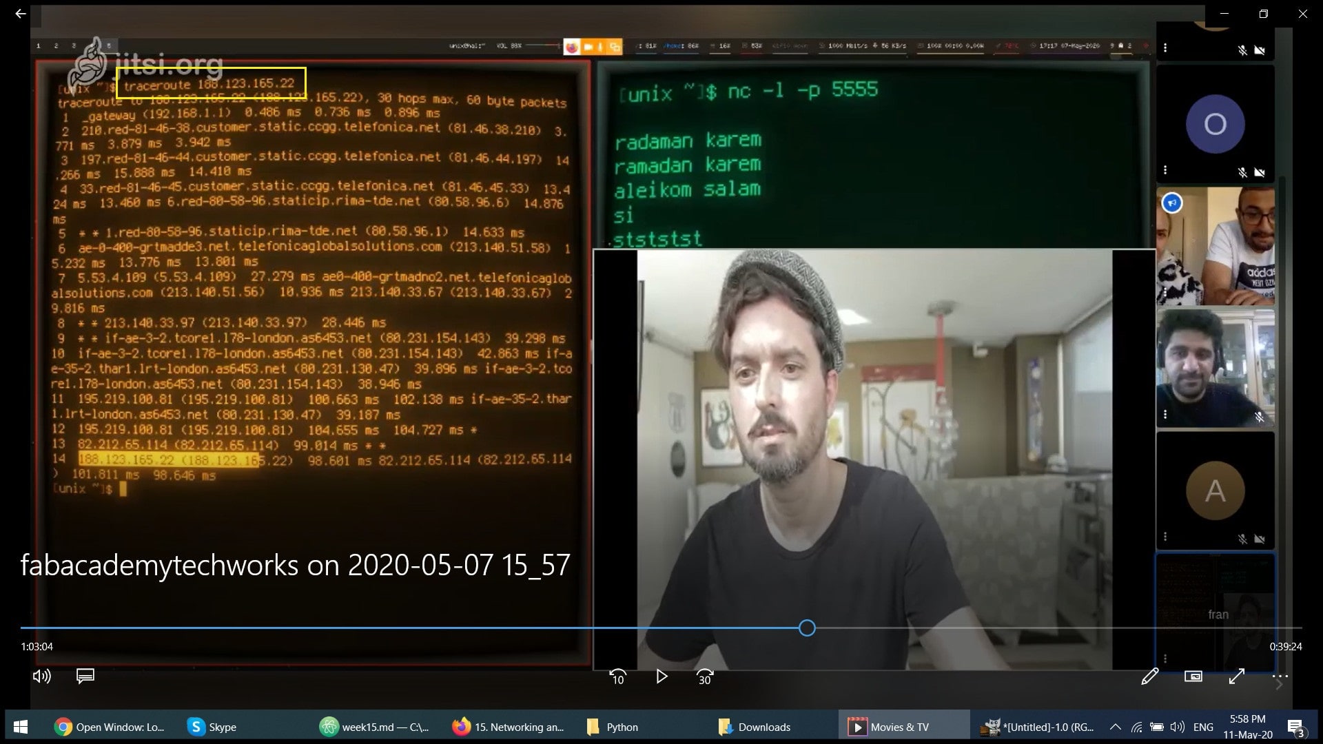
We complete the group assignment in a group call. Using Netcat (nc) under linux, we connected two PCs in two different locations, Frank in Spain with Faisal in Jordan. This is a simple and basic way to create communication beween two PCs to send and receive raw data. Frank used linux, and Faisal used Windows Subsystem for Linux.
Step 1: Frank opened a port in his PC terminal, the port number is 5555. He used the command “nc -l -p 5555”, l for listen and p for port. Now the terminal will be listening to port number 5555 in TCP protocol.
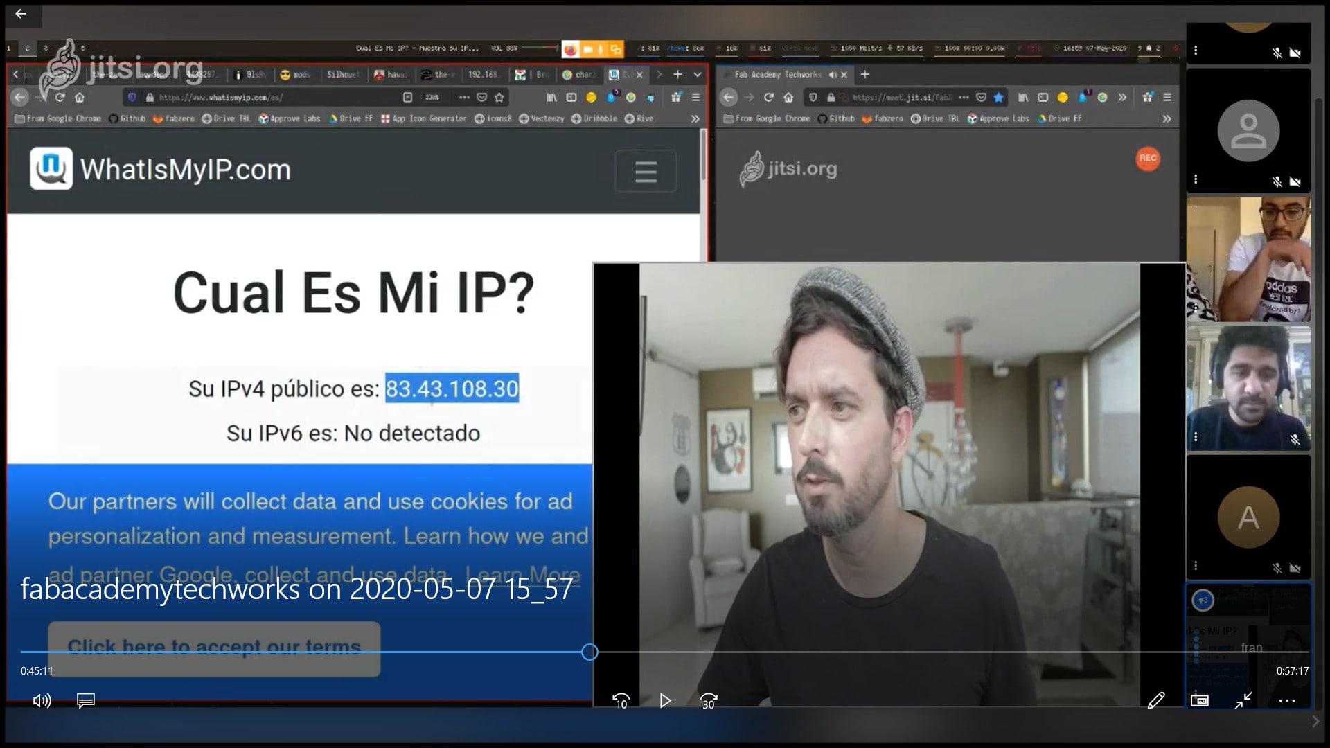
Step 2: Then Frank shared his IP address with Faisal. To open connection with Frank’s open port, Faisal used the command “nc 83.43.108.30 5555”. This command will communicate with port 5555 in the PC at address 83.43.108.30
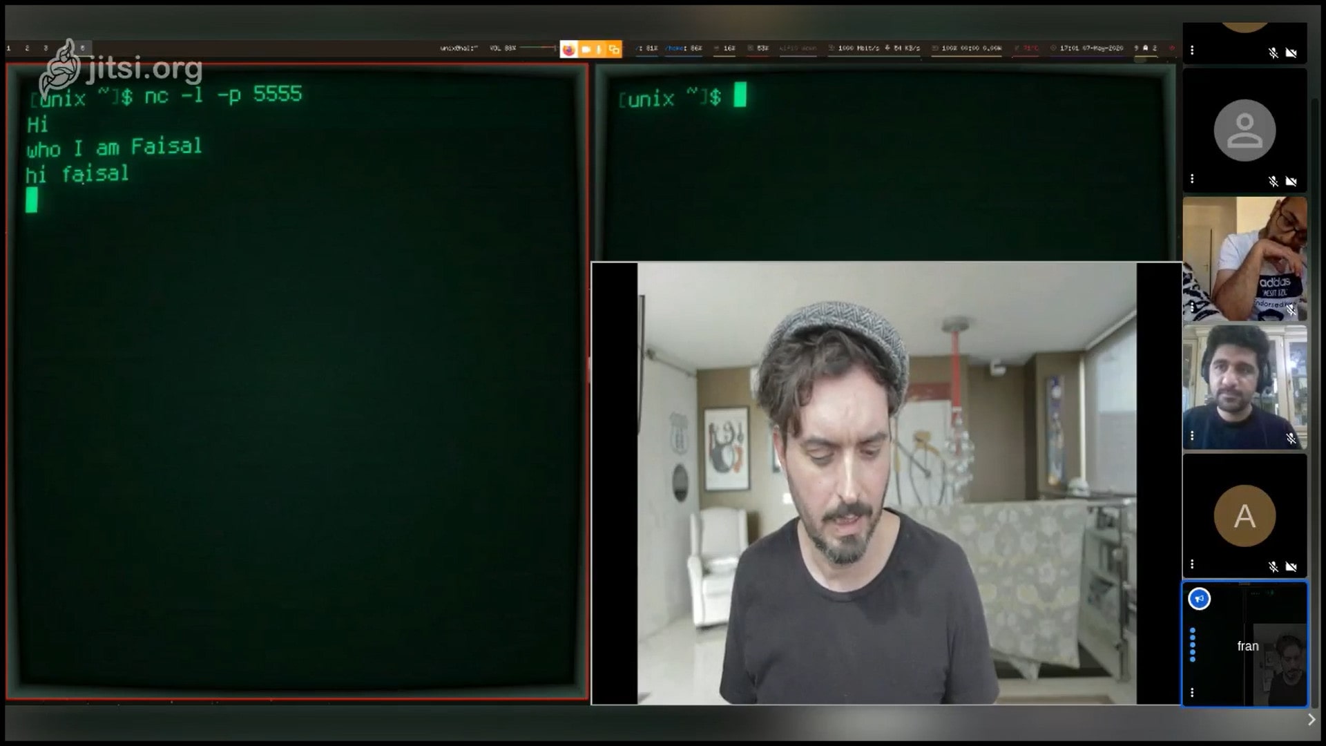
Step 3: Frank and Faisal had this conversation
Faisal: Hi
Frank: who
Faisal: I am Faisal
Frank: hi Faisal
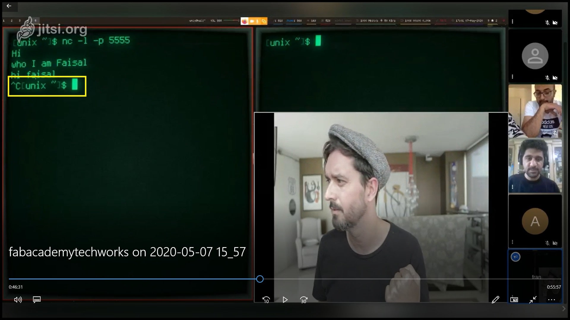
Step 4: To close the terminal port, Frank pressed “CTRL + C”. This will close communication between the terminals.
To trace the connection path between the two PCs, we used the command “traceroute 188.123.165.22”, where the IP address is for the destination PC. In the image below we can see that there were 12 PCs or stages between source and destination PCs.
Week Assignment
File Download
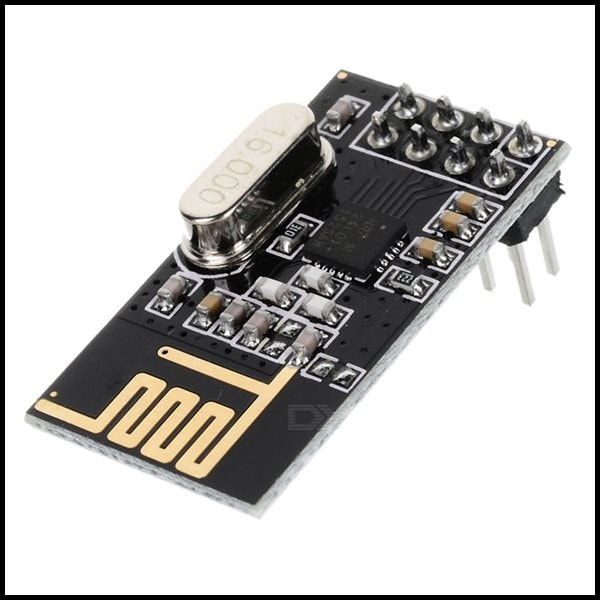
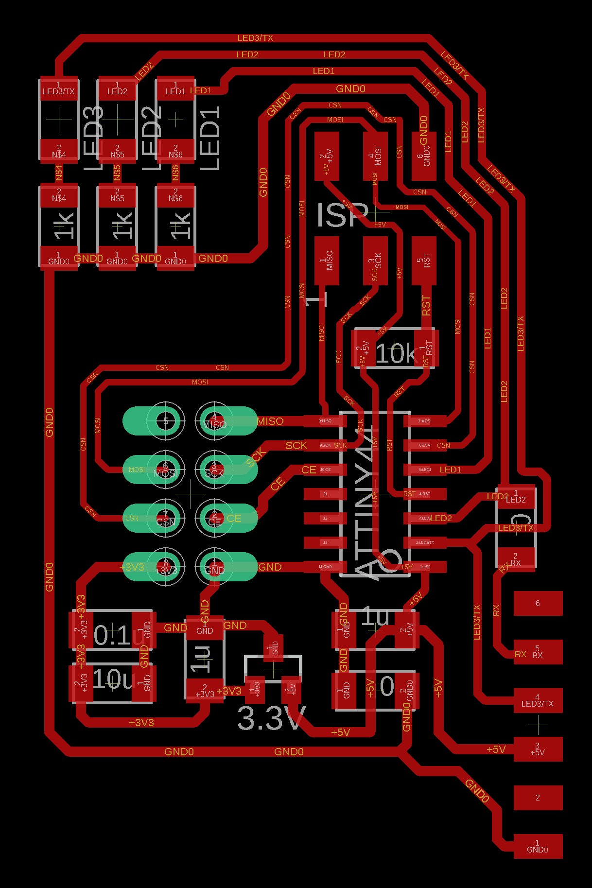
In this week I worked on the NRF24L01+ 2.4GHz Transceiver module. I designed a PCB with three LEDs. I will mill and solder two of that PCB, the first will be working as transmitter and the other as a receiver. Since NRF24L01+ 2.4GHz is a “transceiver”, each board can work as a transmitter or/and a receiver. This is controlled by code.
NRF24L01+ 2.4GHz Transceiver Module
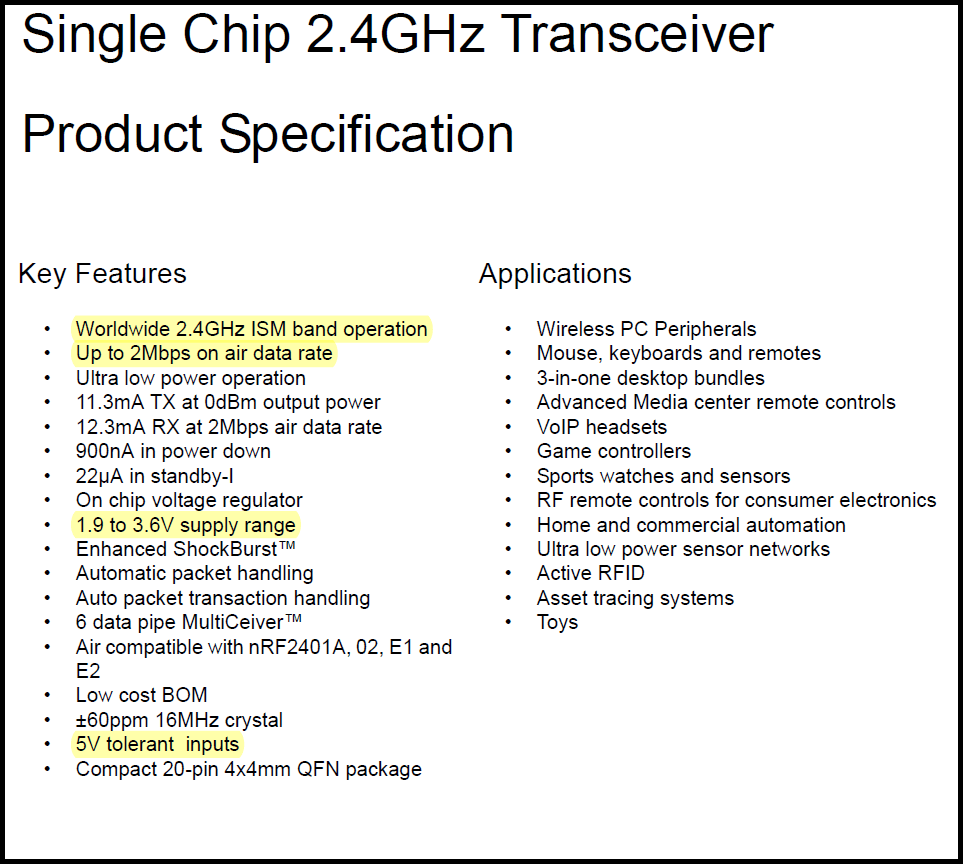
The NRF24L01+ is a 2-way (transceiver) communication module. It could be used to connect two or more boards wirelessly over a distance. It is designed to work on 2.4GHz ISM frequency, and data transfer can be one of 250kbps, 1Mbps and 2Mbps.
The NRF24L01+ supply voltage is 1.9V to 3.6V, which could be easily achieved by using a 3.3V regulator. Other pins can work on 5V, which makes it easy to connect the module to a 5V microcontroller.
The NRF24L01+ module has on board antenna. This makes the system compact in size but limits the range (distance) of communication, and if the module is used indoor between walls the range will be weakened more.
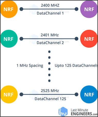
In order for two NRF24L01+ modules to communicate, they should be on the same channel (frequency). “This channel could be any frequency in the 2.4 GHz ISM band or to be more precise, it could be between 2.400 to 2.525 GHz (2400 to 2525 MHz). Each channel occupies a bandwidth of less than 1MHz. This gives us 125 possible channels with 1MHz spacing. So, the module can use 125 different channels which give a possibility to have a network of 125 independently working modems in one place.” Source This is true if 250kbps or 1Mbps data rate are used. If 2Mbps is used, then 2MHhz bandwidth is occupied.
NRF24L01+ has an automatic packet handling. The transmitter sends a data packet to the receiver. When transmission completes, the transmitter waits for an acknowledgement from the receiver. If data packet or acknowledgement is lost, transmitter auto retransmits the same data packet. The packet handling is done automatically by NRF24L01+ module and no code is needed.

The NRF24L01+ module is interfaced through 6 pins plus Vcc (3.3V) and GND. If no interrupts are required, the pin IRQ could be left unconnected.
Week Assignment Part 1: Transmitter/Receiver Making
File Download
NRF24L01+ Transceiver Eagle files
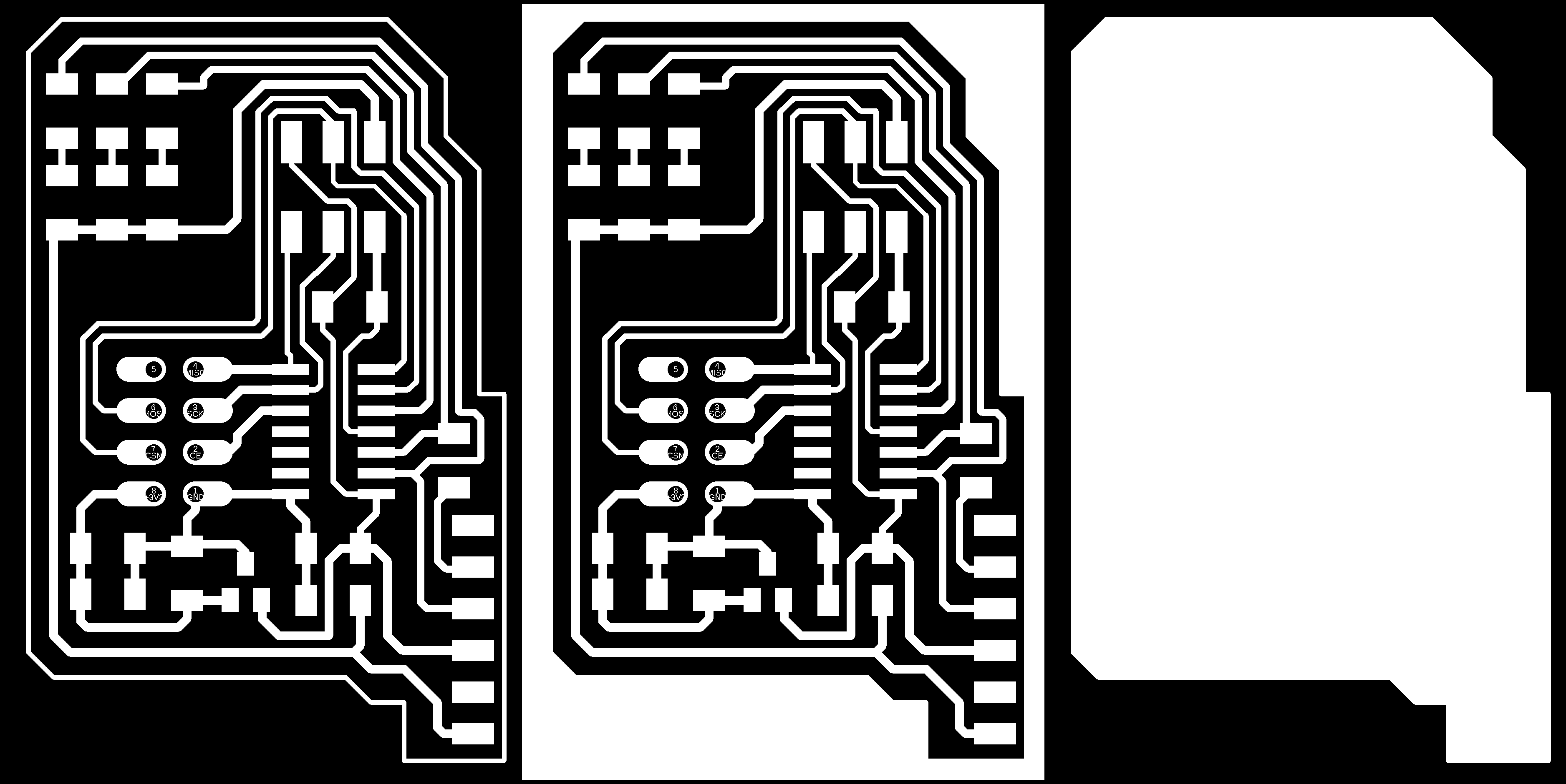
NRF24L01+ traces and interiors png files
NRF24L01+ traces and interiors rml files
NRF24L01+ Transceiver C and Makefiles files
The Transceiver PCB
The PCB is based on ATtiny44 and it could be configured to work as a transmitter or a receiver. The pin IRQ is not connected since I am not using interrupts. Three LEDs are added to the board and also FTDI connector.
If board is configured as a transmitter, the board LEDs will be used to show if data is sent and received successfully through reading acknowledgement from receiver by lighting all LEDs. One the other hand, if the board is configured as a receiver, LEDs will be used to show received data, binary counting from 0 to 7 in my case.
The ATtiny44 will be clocked internally at 8MHz and will be powered through the programmer using the ISP cable.
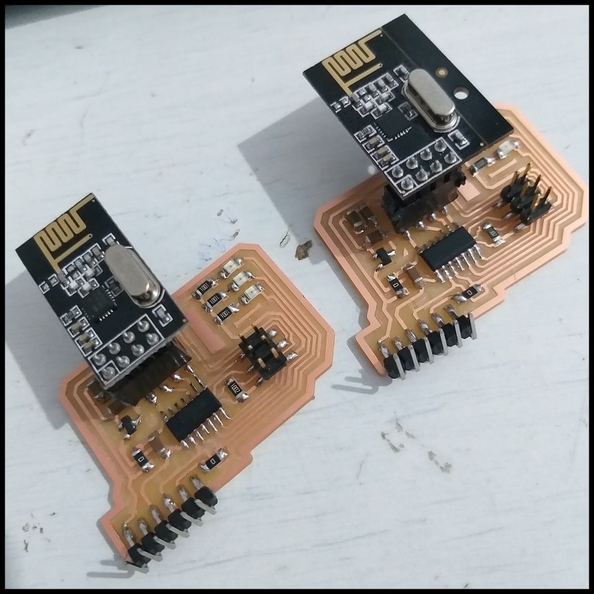
The image below shows the boards. Transmitting and receiving function is determined by code. Both boards are identical.
NRF24L01+ 2.4GHz Module Code
The transmitter code has two files, Transmit.c and nrf24L01Tx.h where all definitions, settings and functions are in the header file. The transmitter sends one byte of data (payload_len = 1) in each cycle. The initial byte value is 48, and in each cycle (500 ms) it is incremented by 1 up to 55. You can increase the payload length by changing “payload_len” variable up to 32 bytes. Note that if data sent and acknowledged, all board LEDs will be turned on, otherwise only one LED will be turned on.
#include <avr/io.h>
#include <util/delay.h>
#include "nrf24L01Tx.h"

int main(){
    uint8_t payload_len = 1;
    uint8_t data_array[1]; //insert payload_len value here
    uint8_t temp;
    uint8_t q = 48;

    //Board Leds
    DDRB |= (1 << PB0) | (1 << PB1) | (1 << PB2);
    PORTB &= ~(1 << PB0) & ~(1 << PB1) & ~(1 << PB2);

   /* init hardware pins */
    nrf24_init();

    /* Channel #2 , payload length */
    nrf24_config(2, payload_len);

    /* Set the device addresses */
    nrf24_tx_address(tx_address);
    nrf24_rx_address(rx_address);

    while(1){
        data_array[0] = q;
        q++;
        if(q == 56){
            q = 48;
        }
        /* Automatically goes to TX mode */
        nrf24_send(data_array);

        /* Wait for transmission to end */
        while(nrf24_isSending());

        /* Make analysis on last tranmission attempt */
        temp = nrf24_lastMessageStatus();

        if(temp == NRF24_TRANSMISSON_OK){
            PORTB |= (1 << PB0) | (1 << PB1) | (1 << PB2);
        }
        else if(temp == NRF24_MESSAGE_LOST){
            PORTB &= ~(1 << PB0) & ~(1 << PB1) & ~(1 << PB2);
        }

        /* Retranmission count indicates the tranmission quality */
        temp = nrf24_retransmissionCount();

        /* Optionally, go back to RX mode ... */
        //nrf24_powerUpRx();

        /* Or you might want to power down after TX */
        // nrf24_powerDown();

        /* Wait a little ... */
        _delay_ms(500);
    }
}
The receiver code has two files, Receive.c and nrf24L01Rx.h where all definitions, settings and functions are in the header file. The receiver reads one byte of data (payload_len = 1) in each cycle, and changing the lighting of board LEDs in binary according to received value.
#include <avr/io.h>
#include <util/delay.h>
#include "nrf24L01Rx.h"

void LEDs(char);
int main()
{
    uint8_t payload_len = 1;
    uint8_t data_array[1]; //insert payload_len here

    //Board Leds
    DDRB |= (1 << PB0) | (1 << PB1) | (1 << PB2);
    PORTB &= ~(1 << PB0) & ~(1 << PB1) & ~(1 << PB2);

    /* init hardware pins */
    nrf24_init();

    /* Channel #2 , payload length: 4 */
    nrf24_config(2, payload_len);

    /* Set the device addresses */
    nrf24_tx_address(tx_address);
    nrf24_rx_address(rx_address);
    //
    // main loop
    //

    while(1)
    {
        if(nrf24_dataReady())
        {
            nrf24_getData(data_array);
            LEDs(data_array[0]);

        }
    }
}

void LEDs(char led){
    switch(led){
        case 48:
            PORTB &= ~(1 << PB0); PORTB &= ~(1 << PB1); PORTB &= ~(1 << PB2);
            break;
        case 49:
            PORTB &= ~(1 << PB0); PORTB &= ~(1 << PB1); PORTB |= (1 << PB2);
            break;
        case 50:
            PORTB &= ~(1 << PB0); PORTB |= (1 << PB1); PORTB &= ~(1 << PB2);
            break;
        case 51:
            PORTB &= ~(1 << PB0); PORTB |= (1 << PB1); PORTB |= (1 << PB2);
            break;
        case 52:
            PORTB |= (1 << PB0); PORTB &= ~(1 << PB1); PORTB &= ~(1 << PB2);
            break;
        case 53:
            PORTB |= (1 << PB0); PORTB &= ~(1 << PB1); PORTB |= (1 << PB2);
            break;
        case 54:
            PORTB |= (1 << PB0); PORTB |= (1 << PB1); PORTB &= ~(1 << PB2);
            break;
        case 55:
            PORTB |= (1 << PB0); PORTB |= (1 << PB1); PORTB |= (1 << PB2);
            break;
        default:
            PORTB &= ~(1 << PB0); PORTB &= ~(1 << PB1); PORTB &= ~(1 << PB2);
            break;
    }
}
In the transmitter and receiver header files, you can change pin assignment for different microcontrollers or different connection.
//define pins
#define CE_port PORTA //CE
#define CE_direction DDRA
#define CE_pin (1 << PA3)
#define CS_port PORTA //CS
#define CS_direction DDRA
#define CS_pin (1 << PA7)
#define SCK_port PORTA //SCK
#define SCK_direction DDRA
#define SCK_pin (1 << PA4)
#define MOSI_port PORTA //MOSI
#define MOSI_direction DDRA
#define MOSI_pin (1 << PA6)
#define MISO_pins PINA //MISO
#define MISO_direction DDRA
#define MISO_pin (1 << PA5)
Problems and Fixes
I was working on the code to send only one byte by changing “payload_len” to 1. At the beginning the system didn’t work, then I found that I only changed payload_len to 1 in transmitter side and didn’t chnage in receiver. After changing payload_len in receiver side to the same value in transmitter side system worked fine.
Hero Shoot!
Week Assignment Part 2 (Extra Material): Code Test Using Breadboard
File Download
NRF24L01+ test C and Makefile files
To test the code, I built a circuit using ATtiny44 Development Board and ATmega328P DIP. I used breadboard to make the connection and tested the system indoor.
Pin connection for transmitter side. Note that IRQ pin in is not connected.
| ATtiny44 | ISP | NRF24L01 | Tests |
|---|---|---|---|
| PA2 | CS | ||
| PA3/RST | RST | ||
| PA4/SCK | SCK | SCK | |
| PA5/MISO | MISO | MISO | |
| PA6/MOSI | MOSI | MOSI | |
| PA7 | CE | ||
| PB2 | LED |
Pin connection for receiver side. Note that IRQ pin in is not connected.
| ATmega328P | ISP | NRF24L01 | Tests |
|---|---|---|---|
| PB1 | CS | ||
| PB2 | CE | ||
| PB3/MOSI | MOSI | MOSI | |
| PB4/MISO | MISO | MISO | |
| PB5/SCK | SCK | SCK | |
| PB6/RST | RST | ||
| PC3 | LED 0 | ||
| PC4 | LED 1 | ||
| PC5 | LED 2 |
Red LEDs in receiver side will count in binary from 0 to 7. If data transferred successfully, the green test LED will light, otherwise it will turn off.