4. Computer Controlled Cutting
Group Assignment
Vinyl Cutter
Machine: Roland CAMM-1 GS-24
This part of the group assignment was about the Roland CAMM-1 GS-24 desktop cutter. We worked on all steps from starting the machine to cutting a sample on the vinyl.
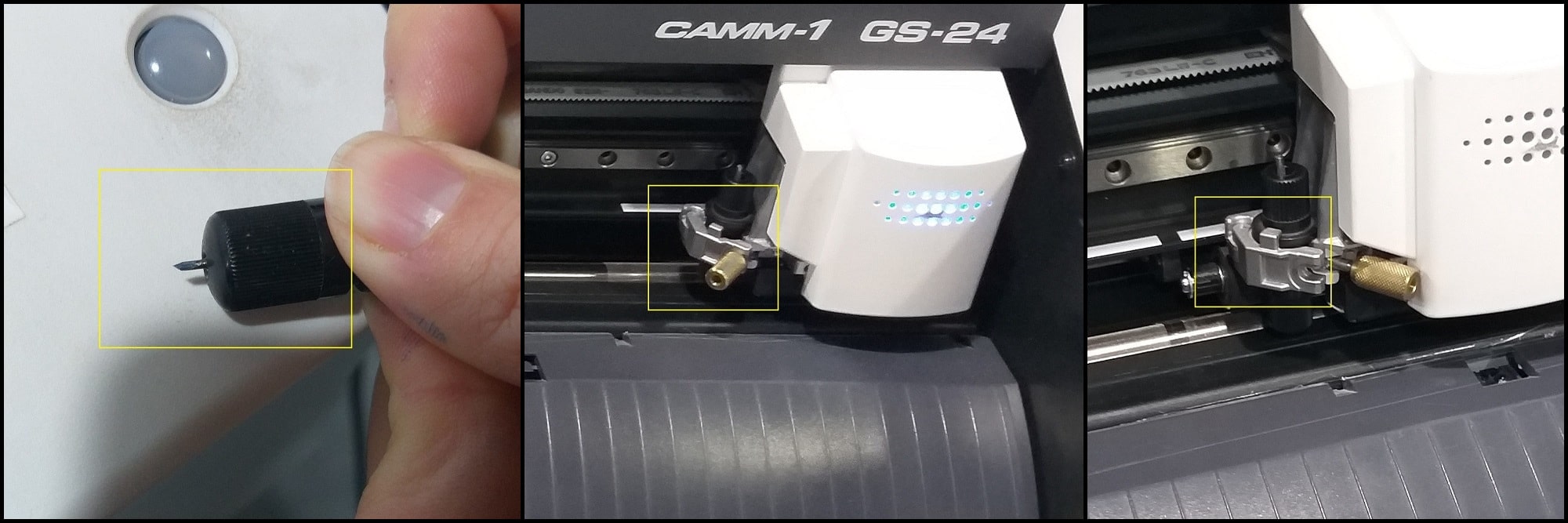
Cutting blade: The cutting blade should be sharp to have a quality cut. You can push the blade from the back end of blade holder to check the blade condition.
To calibrate the blade, we rotated the blade holder cap and tested the blade tip by finger. A good calibration is when you barely feel the blade by finger.
The blade holder then placed into blade carriage. Make sure that the circular edge in the blade holder is in its right place and held by the metal part as shown in the most right image below. The image in middle shows a wrong placement of the blade. Tight the holder screw to hold the blade holder firmly.
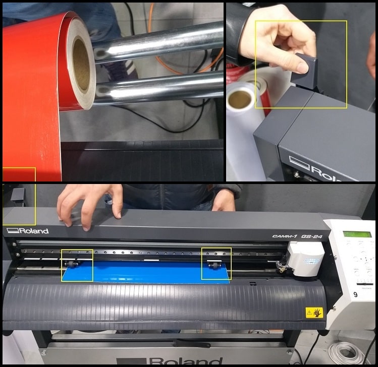
Placing the Vinyl Roll: The vinyl roll is placed on the bars in the back side of the machine. We manually inserted the vinyl under the machine rollers. Make sure to open the holding lever or handle so vinyl could be inserted. To define the cutting width, rollers should be moved in front of white bars on the machine. The working width will be between the two rollers. Move the holding lever or handle to close position to hold roll in position.
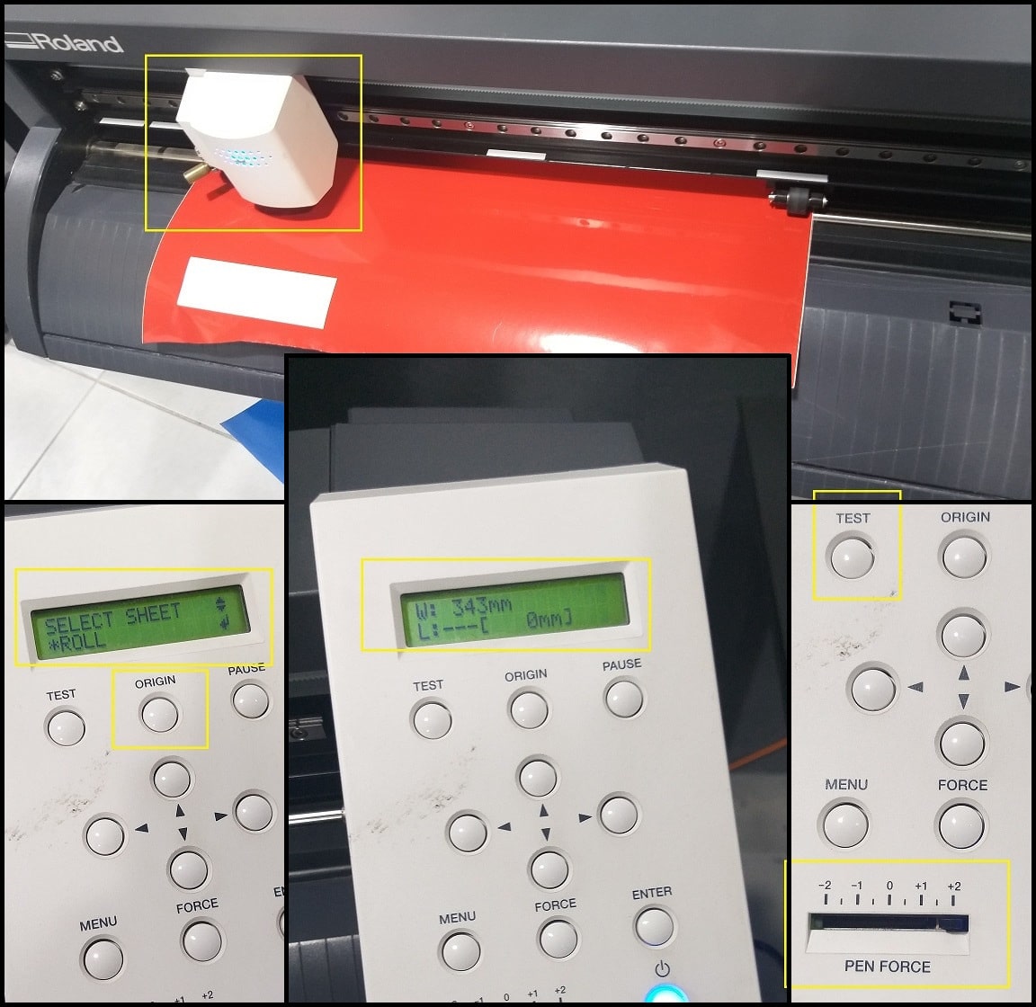
Pen Force: Turn the machine ON. It will find its origin guided by the left roller position. Now the carriage is at origin. You can also program origin manually by a long press on “Origin” button. Then you have to select sheet. Ours was “Roll”. The machine will calculate working width using rollers positions. Using the arrows on control board, you can move sheet manually.
Before starting a new job, the pen force should be tested to make sure that the blade will cut the sticker part of vinyl but not the back paper. To do this press on “Test” and the machine will start cutting a pre-defined shape. If the cut penetrates into vinyl back paper, decrease pen force by moving the slider to the left. If the sticker is not peeling, increase pen force by moving the slider to the right. In our group assignment, a pen force of +2 was the correct setting.
Working on vinyl cutter software is described in Cutting on The Vinyl Cutter in week assignment section.
CNC LASER Cutter
Machine: trotec speedy 400
This part of the group assignment was about the trotec speedy 400 Laser engraving machine. We worked on all steps from starting the machine to engraving and cutting a sample on cardboard, MDF, plywood and acrylic.
Safety First!: Safety cautions and procedures must be considered while working on Laser machines. Please read, understand and apply all caution signs.

Starting the Machine: When the machine is started, the bed will move down and Laser head to left to reference. When reference completes, press “Auto Focus” buttons at the same time for a few seconds. Bed will move upward and Laser beam will be auto focused on its current location by adjusting the bed height.
Focus on Working Piece: This should be completed each time you put a new working piece on machine bed. If necessary, lower the bed by pressing the “AF DOWN” arrow and move Laser head where wanted by pressing up, down, left and right arrow keys. Place the working piece on bed and put “Focus Tool” in the designated place in Laser head. Using the “AF UP” arrow raise the bed by steps till focus tool touches the working piece on bed and falls from its place.
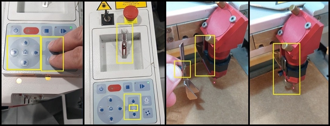
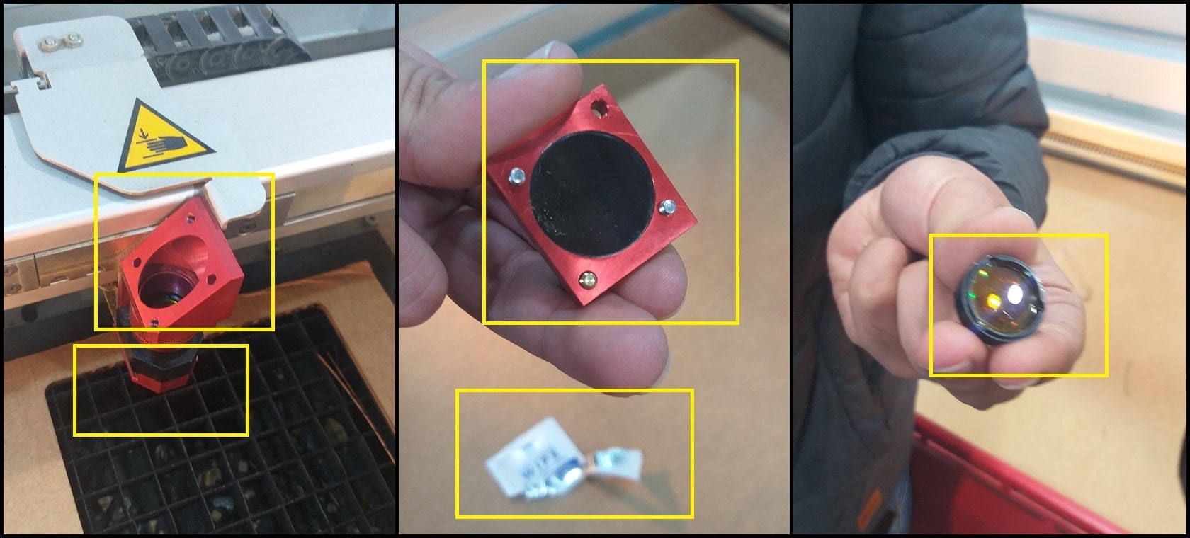
Checking Head Mirror and Lens The head mirror and lens should be checked and cleaned periodically. Unscrew the top of head (two screws) and remove the mirror. Unscrew the head lens holder and remove the lens. Check both for any residuals. If necessary, clean with the special cleaning wipes and avoid touching with fingers. Put head mirror and lens back to their places.
2D Drawing: You can prepare your 2D drawing using Fusion 360, SolidWorks, Rihno or any other program and save your file in dxf format. Then import your file to Inkscape, where you can send your job to machine from print menu. You can use Rihno or Illustrator to draw and send your job to machine without the need to import to another program.
Preparing drawing in Inkscape: The same principle applies to any program of your preference.
After completing your 2D model, save it as dxf file format and open in Inkscape. If you have repeated cuts for the same object, only import one parent object and later use the “Duplicate” command in Inkscape to make more copies.
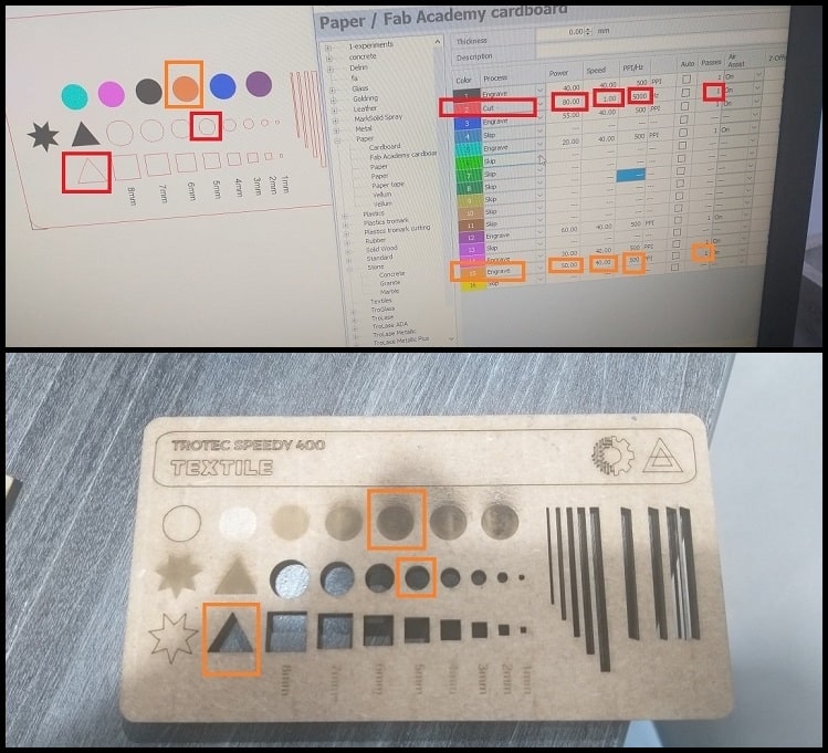
The Laser machine recognizes cutting settings by colors defines in a look up table inside the machine software. For example, anything in RED (RGB = 255, 0, 0) will be cut/engraved using Power = 80.00, Speed = 1.00, Frequency = 5000 and Passes = 1. After importing dxf file to Inkscape, object colors were changed to match with colors in the look up table. For raster, we assigned fill colors to match with the colors in table (for example Black or orange). For outline engraving we assigned the object stroke color to engraving color without filling the object (for example Black or orange). For cutting, we assigned the line color to cutting color (RED in our case) and line stroke to 0.1 mm with no fill. These settings were defined to work on 4.0 mm cardboard.
The table below summarizes settings used on 4.0 mm cardboard.
| Output | Power | Speed | Frequency | Passes | Color |
|---|---|---|---|---|---|
| Cut | 80% | 1% | 5000 Hz | 1 | Red |
| Engrave | 20%-60% | 40% | 500 Hz | 1 | Others |
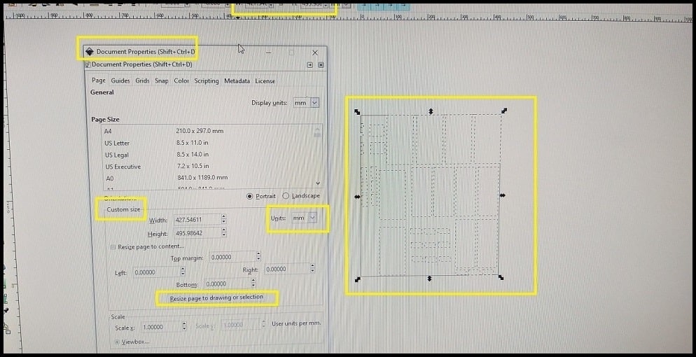
When objects fill, stroke and colors are assigned, make duplicates of objects if needed and then using “Document Properties” in Inkscape, and in “Custom Size” menu, click on “Resize page to drawing or selection”. This would till the size of work piece you need (W and H in the top bar).
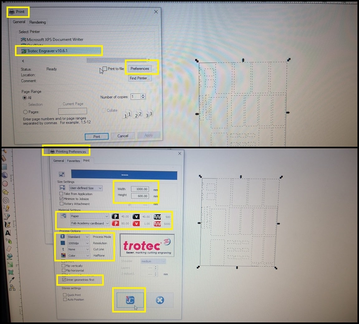
Sending Job to Laser Machine Software: Using “Print” command and selecting “trotec speedy 400” from printers menu, job is ready to send to Laser machine software. Open “Printer Preferences” to check on different settings. Select the right “Material Settings”, which is “Fab Academy cardboard”. This will load the color/power/speed settings from the loop up table. The option “Inner geometries first” will make the machine to work from inside out. To save the settings in machine software we clicked on “JC”. Click on “Print”.
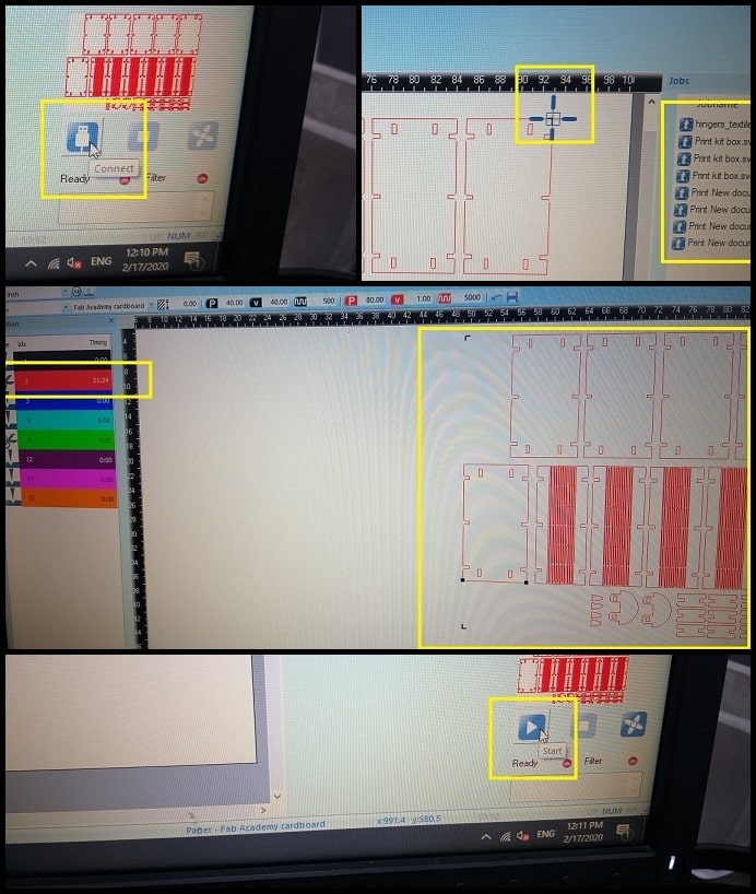
Starting Job: The last steps will open the machine software with your job imported. Click on “Connect” to connect to the machine. Drag you job from the list to the right and drop in working area. You can see the Laser head position in software working area. Then click on the “eye” to view our job. To update the job and match with the look up table, click on “Update”. This shows a color listing to the left showing the function of each; cut or engrave. Move your job, and when we are happy click on “Start”. This started the machine to work our job.
Results: We completed a “press fit” guide for each material. For 4.0 mm cardboard, we found that 3.9 mm cut gives a good hold. From this test we concluded the “kerf” value for 4.0 mm cardboard is 0.1 mm. Note that laser cuts on the center of drawn line.

Also, we made a press fit guide for MDF, acrylic, plywood. And we made five different types of joints.
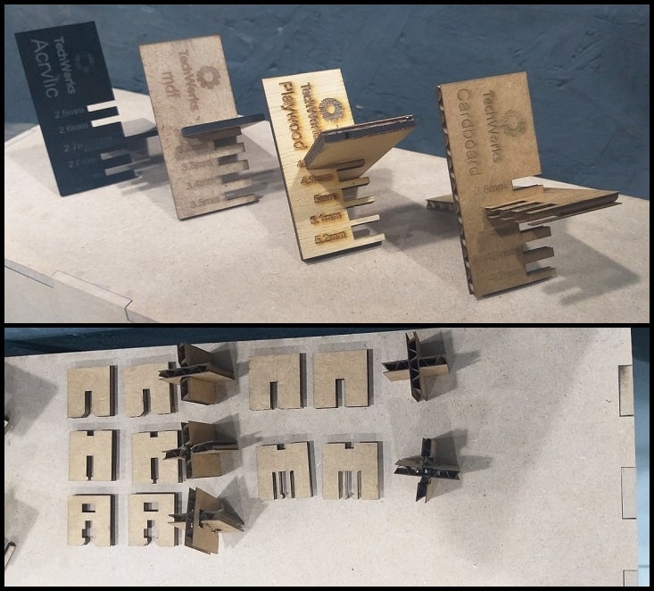
The table below summarizes press fit for different materials.
| Material | Thickness | Press Fit | Kerf |
|---|---|---|---|
| Cardboard | 4.0 mm | 3.9 mm | 0.10 mm |
| Plywood | 5.0 mm | 4.8 mm | 0.20 mm |
| MDF | 3.3 mm | 3.1 mm | 0.20 mm |
| Acrylic | 2.7 mm | 2.7 mm | 0.00 mm |
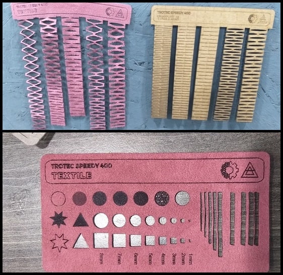
We made also a cut/engrave guide on cardboard using different Laser settings.

And we made a cut/engrave guide on textile, and living hinges using cardboard and textile.
Week Assignment
Cutting on The Vinyl Cutter
File download
Working on CutStudio software
I used the vinyl cutter software “CutStudio” to cut Field Ready logo and “FAB ACADEMY 2020” sticker. I used both on my laptop.
Step 1: Using the “Text” tool, I typed “FAB ACADEMY 2020” in two lines. Then I chose the font and center aligned both lines. The sticker width should be 120 mm to fit to the back of my laptop. In “Size and Shape” menu, I checked “Keep Aspect” option and changed the width to 120 mm.

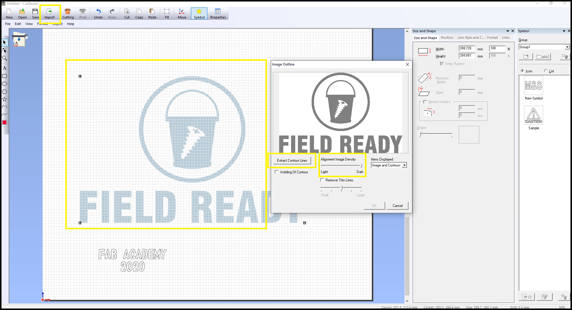
Step 2: I imported Field’s Ready png logo file to the CutStudio. Using the “Image Outline” tool, I changed the value of “Alignment Image density” by moving the slider to dark, and then clicked on “Extract Contour Lines”. These operations created an outline image of the logo.
Step 3: The logo width should be 120 mm to fit to the back of my laptop. In “Size and Shape” menu, I checked “Keep Aspect” option and changed the width to 120 mm.
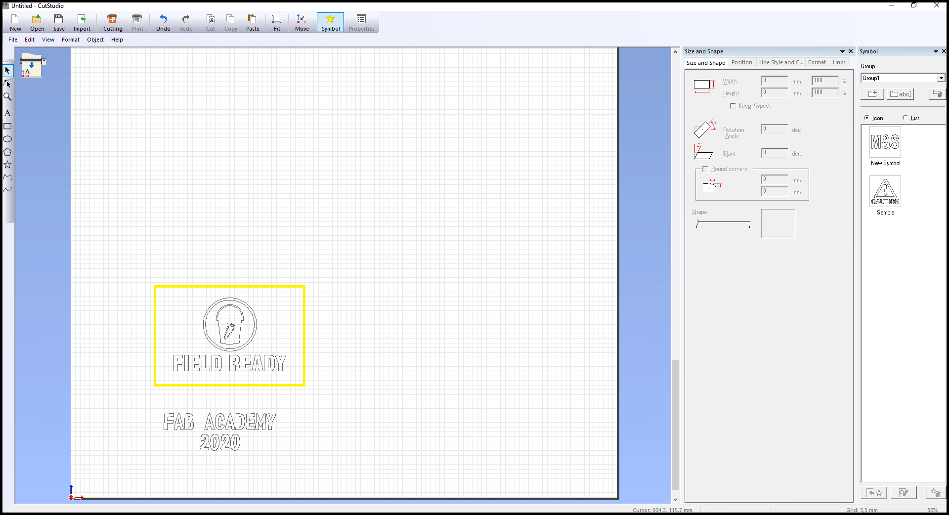
Step 4: I placed the logo outlines image and text into the corner of cutting area (close to origin), then I drew a box around them. The machine will also cut this box. Using the “Cut” command, and from the drop down menu, I selected the best cutting quality “Heavy”. I pressed “OK” and job was sent to machine.

Step 5: After finishing the machine cut, I took the result part and removed all parts I don’t want in my final design.

Step6 : Using paper tape I found at home, I put overlapping strips on my design in order to transfer everything to paper tape while keeping the dimensions of my design. Then I applied pressure to make the design stick well to paper tape.
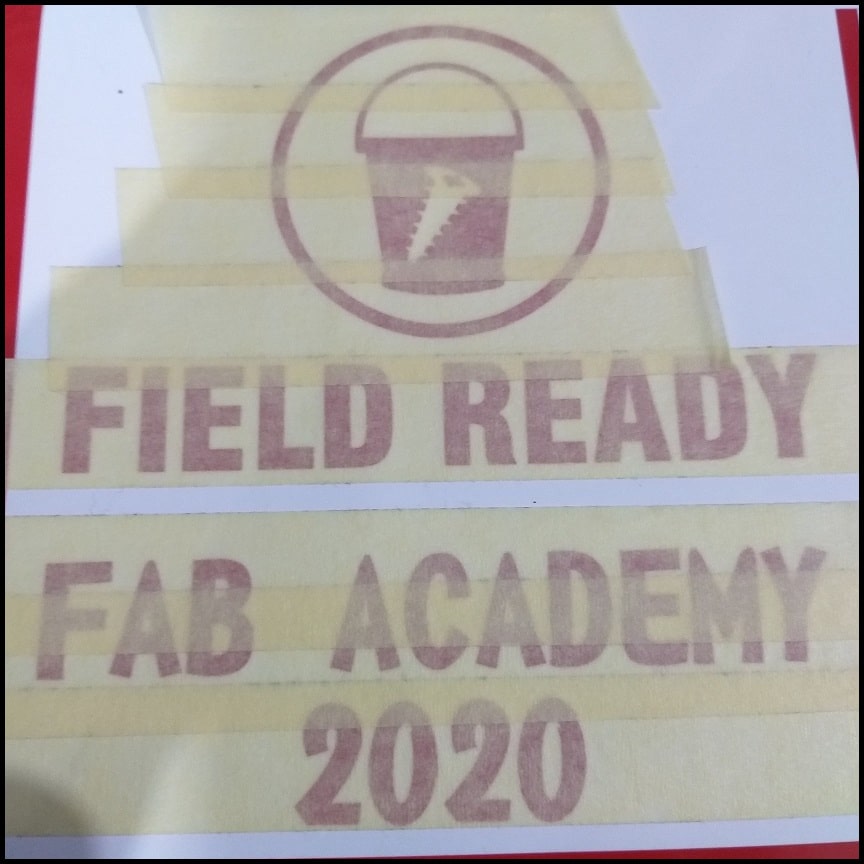
Step 7: I removed paper tape and all characters and shapes in my design transferred to paper tape.

Step 8: I put the paper tape where I want my design to be. I applied pressure to my design to stick to my laptop surface.
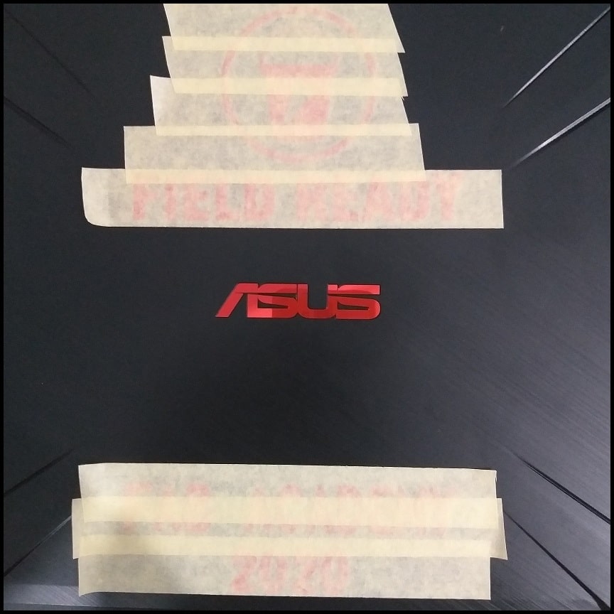
Step 9: Carefully I peeled of the paper tape while giving attention to my design to stay on my lap top. I peeled off the paper tape using small angle.

Hero Shoot!

LASER Cutting Parametric Construction Kit
File download
Construction kit SolidWorks file
Construction kit DXF files
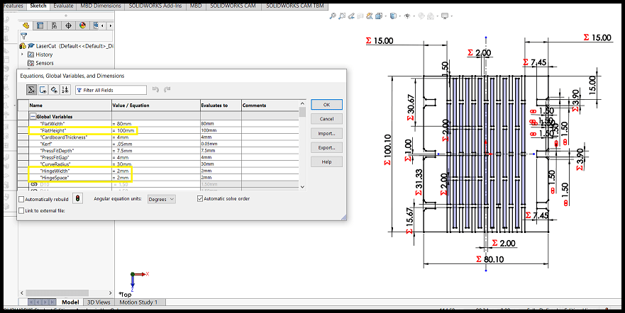
For this assignment I worked on building a construction kit for making flexible open bodies and polygonal bodies. I used SolidWorks to build system components. The design of each block is parametric. Block parameters were defined in “Global Variables” in SolidWorks.
Working on laser cutter software is described in CNC LASER Cutter in group assignment section.

Construction Kit Blocks
The following global variables affect dimensions in all blocks.
Kerf: The value of kerf on 4.0 mm cardboard as determined in group assignment tests. Kerf value will be added/subtracted from cuts to have a good press fit and correct measurements after laser cutting. Cardboard showed good press fit at 3.9 mm, so we concluded kerf value is 0.1 mm.
Note that to make equations simple in SolidWorks the value defined in global variables for “Kerf” is half of the concluded value.
CardBoardThickness: The thickness of cardboard I used for the construction kit. Thickness value will affect press fit slot width. Dimension in drawing is calculated by (CardBoardThickness - 2 * kerf).
PressFitDepth: Controls the distance two pieces will overlap. Dimension in drawing calculate by (PressFitDepth - kerf).
PressFitGap: Controls the gap between joined blocks.
Flat Block: Flat block is controlled by the following global variables.
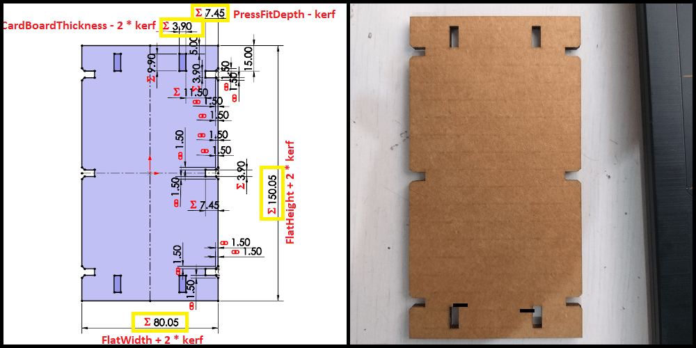
FlatWidth: Controls the base width of the flat block. Dimension in drawing is calculated by (FlatWidth + 2 * kerf).
FlatHeight: Controls the height of the flat block. Dimension in drawing is calculated by (FlatHeight + 2 * kerf).
Hinge Block: Flat block is controlled by the following global variables.
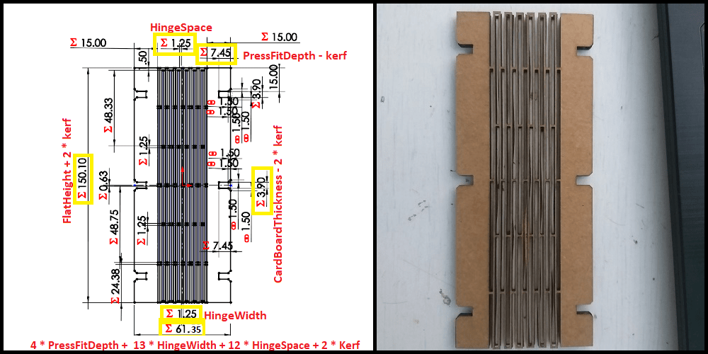
FlatHeight: Controls the height of the hinge block. Dimension in drawing is calculated by (FlatHeight + 2 * kerf).
HingeWidth: Controls the width of cut in the hinge pattern. Dimension in drawing is calculated by (HingeWidth).
HingeSpace: Controls the space between cuts in the hinge pattern. Dimension in drawing is calculated by (HingeSpace).
PressFitDepth, HingeWidth and HingeSpace: Controls the base width of living hinge. Dimension in drawing is calculated by (4 * PressFitDepth + 13 * HingeWidth + 12 * HingeSpace + 2 * Kerf).
Horizontal Joint Block: This block is used to join flat block and hinge block Horizontally. Horizontal joint block is controlled by the following global variables.
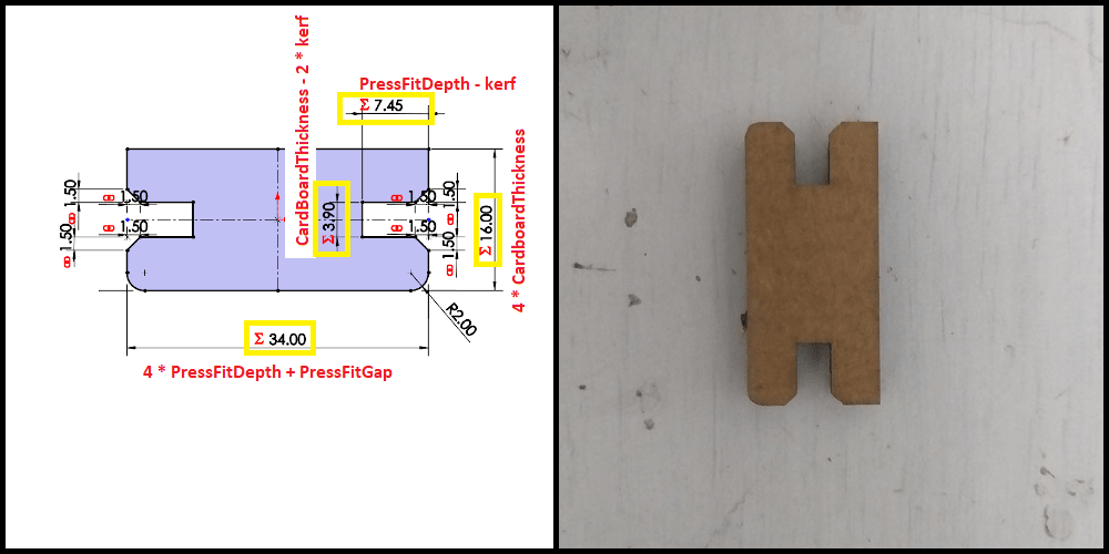
PressFitDepth and PressFitGap: Controls the width of horizontal joint block. Dimension in drawing is calculated by (4 * PressFitDepth + PressFitGap).
CardBoardThickness: Controls the height of horizontal joint. Dimension in drawing is calculated by (4 * CardboardThickness).
Horizontal Double Joint Block: This block is used to join bodies horizontally through their flat blocks. Horizontal double joint block is controlled by the following global variables.
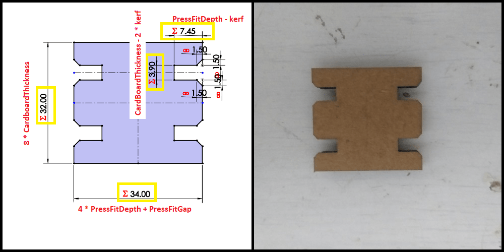
PressFitDepth and PressFitGap: Controls the width of horizontal double joint block. Dimension in drawing is calculated by (4 * PressFitDepth + PressFitGap).
CardBoardThickness: Controls the height of horizontal double joint. Dimension in drawing is calculated by (8 * CardboardThickness).
Vertical Joint with Wedge Block: This block is used to join bodies vertically through their flat blocks. Vertical joint block is controlled by the following global variables.
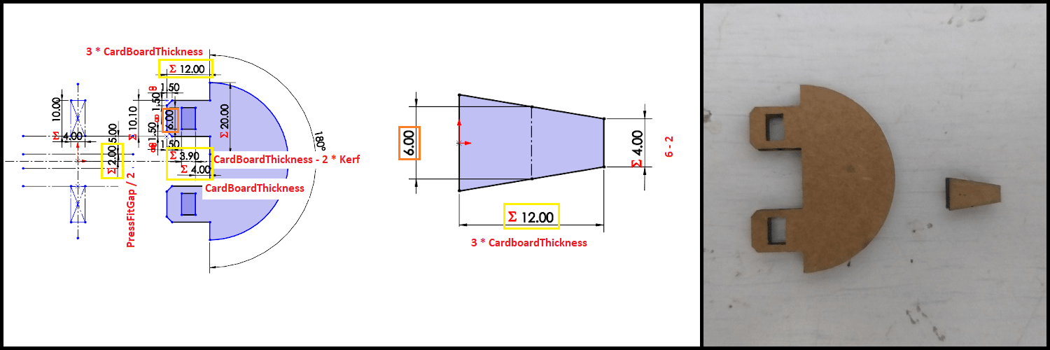
CardBoardThickness: Controls the wedge length, the opening where the wedge will go and the length of insert in vertical joint. Dimensions related to CardBoardThickness are shown on drawing.
PressFitGap: Controls the internal height of the vertical joint. The dimension in drawing is calculated by (PressFitGap / 2).
Parametric Design Test
Images below show the living hinge dimensions using different values for FlatHeight, HingeWidth and HingeSpace. Notice that all parametric dimensions reflecting the changes in global variables while maintaining all relations in drawing.

Construction Kit Assembly
To cut on Laser machine, I used theh setting Below
The table below summarizes settings used on 4.0 mm cardboard.
| Output | Power | Speed | Frequency | Passes | Color |
|---|---|---|---|---|---|
| Cut | 80% | 1% | 5000 Hz | 1 | Red |
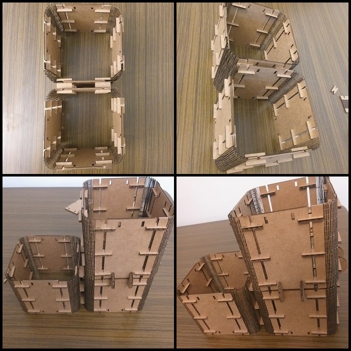
The kit utilized 3 techniques to complete assembly and achieve the desired function. For assembly I used chamfer and wedge joints, and for flexibility I used living hinges.
Image below shows the horizontal joint, horizontal double joint and vertical joint with wedge.
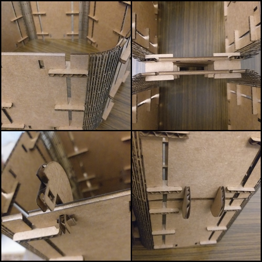
Below the functionality of the living hinge and some assembly ideas for the flexible open and polygonal bodies.

Image below shows horizontal and vertical expansion for the base body. The expansion is made possible by the horizontal single and double joint, and by vertical joint with wedge.