9. Embedded Programming
Group Assignment
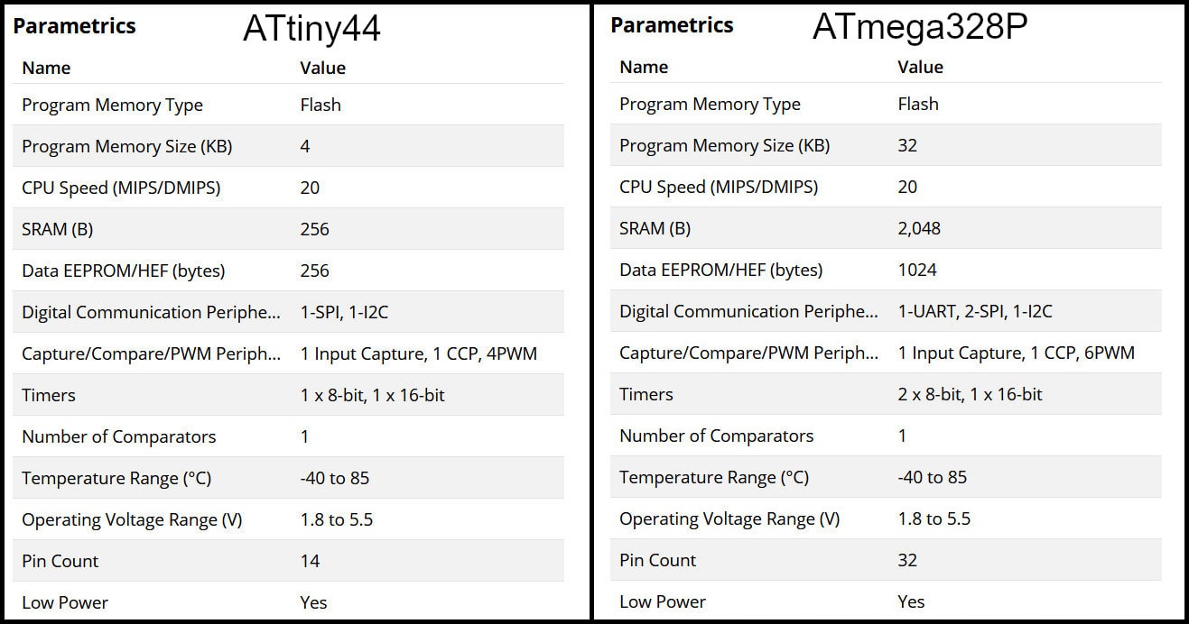
In this part we compared between two AVR families, ATtiny44 from tinyAVR family and ATmega328P from megaAVR family. For ATtiny44 we used avr-dude and FabTinyISP programmer and for ATmega328P we used Arduino UNO board.
Feature Comparison
The table below compares bwteen the two MCUs. “tinyAVR microcontrollers (MCUs) are optimized for applications that require performance, power efficiency and ease of use in a small package”, where “megaAVR microcontrollers (MCUs) are the ideal choice for designs that need some extra muscle. For applications requiring large amounts of code.” Source
Programming ATtiny44 using avr-dude
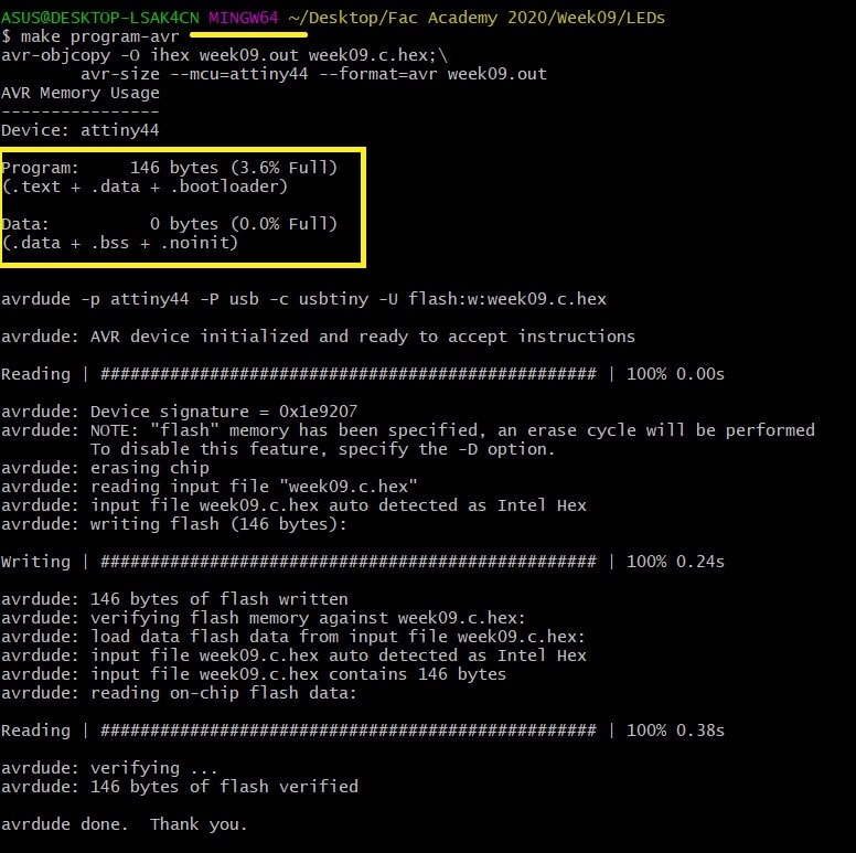
Write the program in C language using Notepad++ text editor. In the Makefile, define settings like programmer, target MCU, clock rate and lfuse. Using “make” command, build the hex file to be uploaded to target MCU. Connect the FabTinyISP prorammer to USB and ISP cable between programmer and target board. Using the command defined in Makefile “make program-avr-fuses”, program the lfuse to target MCU. Using the command defined in Makefile “make program-avr”, upload the hex file to target MCU.
Programming ATmega328P Using Arduino UNO Board
Write code using Arduino commands. The target MCU should have the right bootloader burnt to be used on Arduino Uno board. Connect the board to USB and uplad the hex file. To butn a bootloader to a fresh ATmega328P, you can check the built in example from Arduino.
avr-dude Vs. Arduino
Programming in C enables users to have more control and optimized execution. The code written in C occupies less memory than the code written in Arduino. Also, code written in C executes faster. Kepe in mind to program in C, the MCU should not have a bootloader burnt to it, which saves the flash memory needed for the bootloader.
The follwing codes blink a LED on pin PB0 in ATmega328P MCU. The first code using C language and avr-dude and the second using Arduion IDE.
//Using C and avr-dude
#include <avr/io.h>
#include <util/delay.h>

int main()
{
    DDRB |= (1 << PB0);
    while(1){
        PORTB |= (1 << PB0);
        _delay_ms(500);
        PORTB &= ~(1 << PB0);
        _delay_ms(500);
    }
}
//Using Arduio IDE
void setup() {
  // put your setup code here, to run once:
  pinMode(8, OUTPUT); //PB0
}

void loop() {
  // put your main code here, to run repeatedly:
  digitalWrite(8, HIGH);
  delay(500);
  digitalWrite(8, LOW);
  delay(500);
}
After compiling both codes, we can compare memory usage. The image below shows the result after compiling both codes.
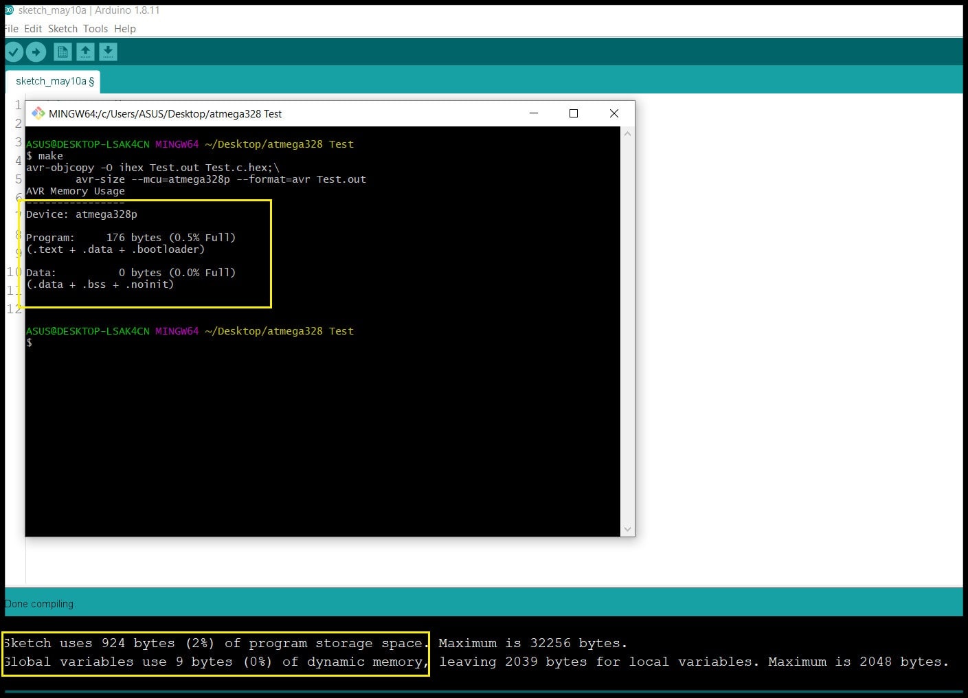
To summarize, the table below shows memory requiremets for both approaches. Note that in both codes the target MCU is ATmega328P.
| avr-dude C | Arduino IDE | |
|---|---|---|
| Flash | 176 bytes | 924 bytes |
| SRAM | 0 bytes | 9 bytes |
Week Assignment
File Download
ATtiny44 datasheet
Example Code #1 Makefile and C file
Example Code #2 Makefile and C file
Example Code #3 Makefile and C file
In this week I programmed the board I made in Electronics Design week. The board is based on ATtiny44 and has FTDI port. I added two LEDs and a push button to the original design, and used AVR-GCC toolchain in C language to write the code, and avrdude to upload HEX file to the ATtiny44.
Pinout and Block Diagram
In Electronic Design week, I added to LEDs to pins 10 and 11 (PA3 and PA2) and a push button to pin 5 (PB2). The block diagram shows the width of PORTA (8-bit) and PORTB (4-bit).
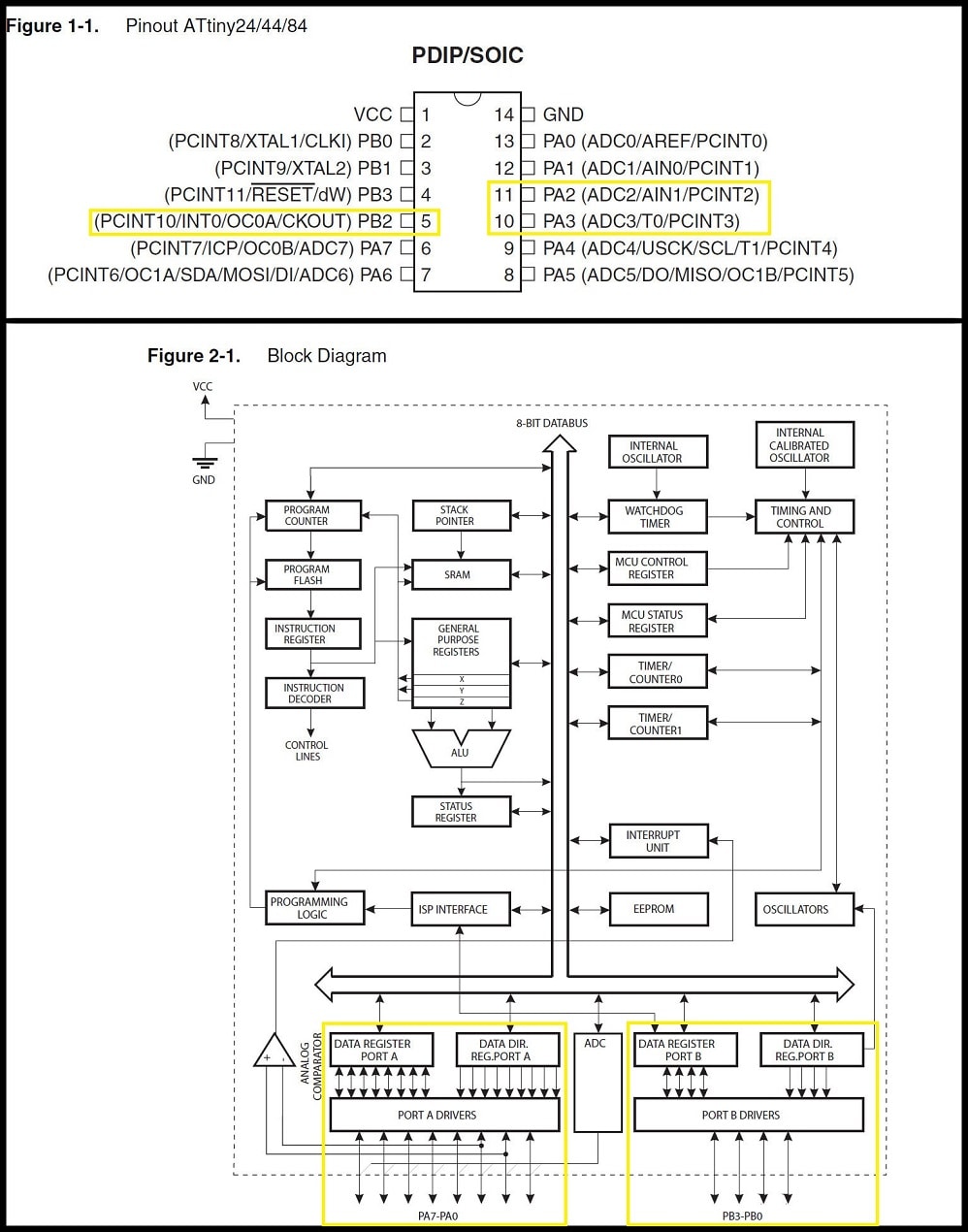
Sorce: ATtiny44 datasheet, pages 2 & 4
Digital I/O Ports Registers
ATtiny44 has two I/O ports: PORTA (8-bit bidirectional) and PORTB (4-bit bidirectional).
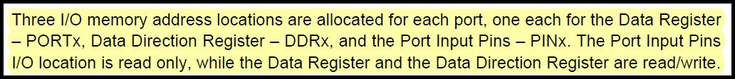 Sorce: ATtiny44 datasheet, page 53
For example, for port “A”, the Data Register is “PORTA”, Data Direction Register is “DDRA” and Port Input Pins is “PINA”. These registers will be used when writing a code to be uploaded to the ATtiny44.
 Sorce: ATtiny44 datasheet, page 54
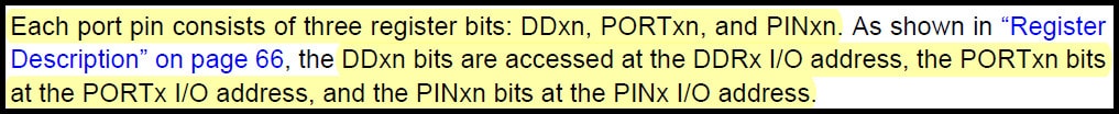
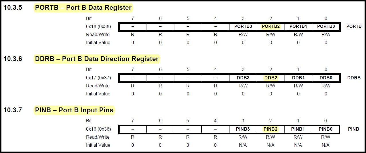
This means that each port pin has its out register bits. For example, for pin “2” in port “B”, the Data Register Bit is PORTB2, Data Direction Register Bit is DDRB2 and Port Input Pins Bit is PINB2.
 Sorce: ATtiny44 datasheet, page 67
Configuring Port Pins
Each pin in both ports can be defined as an output pin or as an input pin. This is done by the data direction register bits. If port pin is configured as input, then the port pin value can be read using port input pin bit. If port pin is configured as output, then the port pin value can be written using the data register bit. The example explains this for pins ” 2” and “3” in port “A”.
DDRA |= (1 << DDA2); //Configure pin 2 in port A as output
PORTA |= (1 << PORTA2); //Write logic 1 to pin 2 in port A
PORTA &= ~(1 << PORTA2); //Write logic 0 to pin 2 in port A

DDRA &= ~(1 << DDA3); //Configure pin 3 in port A as input
if(PINA & (1 << PINA3)){} //True when the value of pin 3 in port A is logic 1
if(!(PINA & (1 << PINA3))){} //True when the value of pin 3 in port A is logic 0
Fuse Low Byte
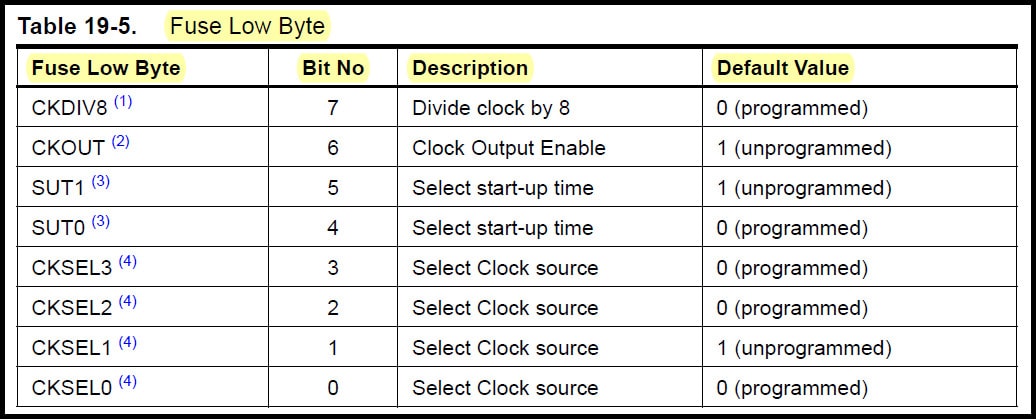
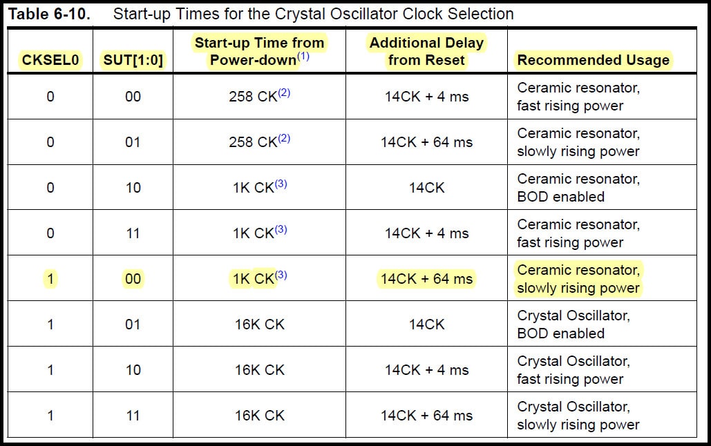
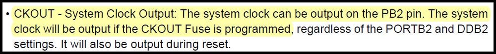
Fuse Low Byte (lfuse) controls clock source, start-up time and, clock division and clock output enabled on CKOUT pin (PB2). lfuse should be programmed only for one time at the beginning, and it is not affected by reprogramming the flash memory.
 Sorce: ATtiny44 datasheet, page 160
I used the settings below for the lfuse
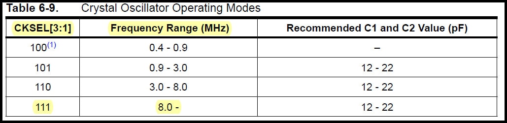
CKSEL3:1 = 111 External 20MHz ceramic resonator.
 Sorce: ATtiny44 datasheet, page 29
SUT1:0 = 00, CKSEL0 = 1 1K CK start-up time from power-down, 14CK + 64 ms additional delay from reset.
 Sorce: ATtiny44 datasheet, page 29
CKOUT = 1: Output system clock on CKOUT pin (PB2) disabled (unprogrammed).
 Sorce: ATtiny44 datasheet, page 64
CKDIV8 = 1: System clock prescaling 1:1 (CKDIV8 unprogrammed).
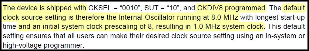 Sorce: ATtiny44 datasheet, page 30
The table below summarize the lfuse value. The value of lfuse should be written in the Makefile and programmed using “make avr-program-fuses” command
| CKDIV8 | CKOUT | SUT1:0 | CKSEL3:1 | CKSEL0 | Binary | Hexadeciaml |
|---|---|---|---|---|---|---|
| 1 | 1 | 00 | 111 | 1 | 11001111 | 0xCF |
The makefile
Makefile defines some settings and commands used to program the ATtiny44. The Makefile code below stores ceramic resonator speed, project name, programmer, target board, lfuse value and two commands used to program ifuse (program-avr-fuses) value and upload hex file (program-avr).
PROJECT=week09
SOURCES=$(PROJECT).c
MMCU=attiny44
PROGRAMMER=usbtiny
F_CPU = 20000000
l_fuse=0xCF

CFLAGS=-mmcu=$(MMCU) -Wall -Os -DF_CPU=$(F_CPU)

$(PROJECT).hex: $(PROJECT).out
    avr-objcopy -O ihex $(PROJECT).out $(PROJECT).c.hex;\
    avr-size --mcu=$(MMCU) --format=avr $(PROJECT).out

$(PROJECT).out: $(SOURCES)
    avr-gcc $(CFLAGS) -I./ -o $(PROJECT).out $(SOURCES)

program-avr: $(PROJECT).hex
    avrdude -p $(MMCU) -P usb -c $(PROGRAMMER) -U flash:w:$(PROJECT).c.hex

program-avr-fuses: $(PROJECT).hex
    avrdude -p $(MMCU) -P usb -c $(PROGRAMMER) -U lfuse:w:$(l_fuse):m
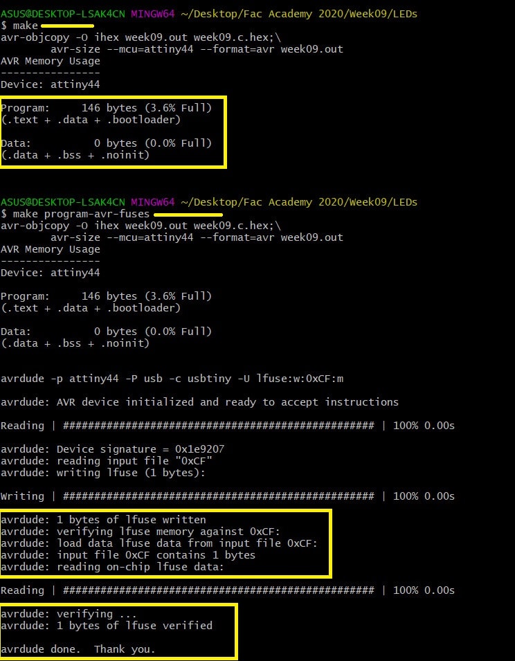
Using “make” command generates the hex file for the code and “make avr-program-fuses” writes the value 0xCF into the “lfuse” register in the ATtiny44. After using “make” command, you can check memory needed to store your hex file.
Example Code #1
The code below changes LEDs lighting according to presses count on the push button.
#include <avr/io.h>
#include <util/delay.h>

void switchLED(unsigned char);

int main(void) {
    //Clock divider set to one using lfuse bit CKDIV8 = 1
    unsigned char counter = 1; //Counts push button presses
    double Tdebounce = 150; //Delay to remove debouncing

    DDRA |= (1 << DDA2); //Output: Red LED
    DDRA |= (1 << DDA3); //Output: Blue LED
    DDRB &= ~(1 << DDB2); //Input: Push button. Default = 1 (pulled up through external 10k resistor)

    while(1){
        if(!(PINB & (1 << PINB2))){ //If push button pressed
            _delay_ms(Tdebounce);
            while(!(PINB & (1 << PINB2))){} //Looping as long as push button is pressed
            counter++;
            if(counter == 5){
                counter = 1;
            }
        }
        switchLED(counter);
    }
}

void switchLED(unsigned char c){
    switch(c){
        case 1: //Both LEDs ON
        PORTA |= (1 << PORTA2);
        PORTA |= (1 << PORTA3);
        break;
        case 2: //Red LED ON
        PORTA |= (1 << PORTA2);
        PORTA &= ~(1 << PORTA3);
        break;
        case 3: //Blue LED ON
        PORTA &= ~(1 << PORTA2);
        PORTA |= (1 << PORTA3);
        break;
        case 4: //Both LED OFF
        PORTA &= ~(1 << PORTA2);
        PORTA &= ~(1 << PORTA3);
        break;
    }
}
After making the hex file, command “make avr-program” command is used to upload the hex file to ATtiny44 flash memory. Note that 146 bytes (out of 4K byte) of flash used to upload the hex file, and 0 bytes (out of 256 bytes) of SRAM used.
Example Code #2
The code below changes LEDs lighting according to presses count on the push button. Here I used macros to changes the output pins value and to test the input pin value.
#include <avr/io.h>
#include <util/delay.h>

#define bitHigh(reg, bit) (reg) |=  (1 << (bit))
#define bitLow(reg, bit) (reg) &= ~(1 << (bit))
#define bitState(reg, bit) (reg) & (1 << (bit))

void switchLED(unsigned char);

int main(void) {
    //Clock divider set to one using lfuse bit CKDIV8 = 1
    unsigned char counter = 1; //counts push button presses
    double Tdebounce = 150; //Delay to eliminate debouncing

    DDRA |= (1 << DDA2); //Output: Red LED
    DDRA |= (1 << DDA3); //Output: Blue LED
    DDRB &= ~(1 << DDB2); //Input: Push button. Default = 1

    while(1){
        if(!(bitState(PINB, PINB2))){ //If push button pressed
            _delay_ms(Tdebounce);
            while(!(bitState(PINB, PINB2))){} //Loop as long as push button pressed
            counter++;
            if(counter == 5){
                counter = 1;
            }
        }
        switchLED(counter);
    }
}

void switchLED(unsigned char c){
    switch(c){
        case 1: //Both LEDs ON
        bitHigh(PORTA, PORTA2);
        bitHigh(PORTA, PORTA3);
        break;
        case 2: //Red LED ON
        bitHigh(PORTA, PORTA2);
        bitLow(PORTA, PORTA3);
        break;
        case 3: //Blue LED ON
        bitLow(PORTA, PORTA2);
        bitHigh(PORTA, PORTA3);
        break;
        case 4: //Both LED OFF
        bitLow(PORTA, PORTA2);
        bitLow(PORTA, PORTA3);
        break;
    }
}
Example Code #3
The code below toggles the output pins value when the push button is pressed. Writing logical 1 to PINA2 and PINA3 will toggle the output values on PORTA2 and PORTA3.
 Sorce: ATtiny44 datasheet, page 55
#include <avr/io.h>
#include <util/delay.h>

int main(void) {
    //Clock divider set to one using lfuse bit CKDIV8 = 1

    DDRA |= (1 << DDA2); //Output: Red LED
    DDRA |= (1 << DDA3); //Output: Blue LED
    DDRB &= ~(1 << DDB2); //Input: Push button. Default = 1

    while(1){
        if(!(PINB & (1 << PINB2))){ //If push button pressed
            PINA |= (1 << PINA2);
            PINA |= (1 << PINA3);
            _delay_ms(250);
        }
        else{
            PORTA |= (1 << PORTA2);
            PORTA |= (1 << PORTA3);
        }
    }
}
Hero Shoot!
Example Code #1 & Example Code #2
Example Code #3