12. Output Devices
Group Assignment
In this part we measured the power consumption of a DC motor using a DC motor output board. Power (in Watt) is calculated by P = V x I, where V is the voltage across the load and I is the current passing through the load. To measure voltage, the digital multimeter (DMM) is connected in parallel with the load, and to measure the current passing through, the DMM is connected in series with the load. Remember to move DMM positive test lead to current measuring position before connecting in series with the load.

To calculate the power consumption of the DC motor:
P = 12.15 x 0.08
P = 0.972 Watt
P = 972 mWatt
Week Assignment
In this week I designed a PCB that will be connected to my ATtiny44 Development Board to control a unipolar stepper motor.
Week Assignment Part 1: Stepper Driver PCB
File Download
NDS355AN N-Channel MOSFET Datasheet
Eagle stepper driver ZIP file
Stepper driver traces png file
Stepper driver interiors png file
Stepper driver C and Makefile
The SM-E040 Stepper Motor
Stepper motors are DC motors that move is discrete steps. Inside the motor there are windings that are grouped into phases. The stepper I am using has 6 wires, 3 for each winding and each winding is center tapped, which results in 4 phases.

If the center tapping wires used, then the motor will be driven as a unipolar stepper using 4 switches, and if only 4 wires used (both windings ends), the motor will be driven as a bipolar stepper and two h-bridges will be used. I will use all wires and operate the motor as a unipolar stepper.
I looked for a datasheet for the stepper (I got it from an old printer) but couldn’t find any. I made some tests mapped the wires as shown below.
| Phase A | Phase B |
|---|---|
| Brown: A com | Brown: B com |
| Orange: A | White: B |
| Blue: A’(C) | Pink: B’(D) |
The winding resistance(A-A’ and B-B’) is 100 Ohms. I assumed 12VDC input which result in 240 mA passing in each phase (A com-A, A com-A’, B com-B, B com-B’). The stepper resolution is 48 Steps.
Drive Mode
The motor can be driven in wave drive (single coil excitation), full step drive (double coils excitation), half stepping and micro stepping.
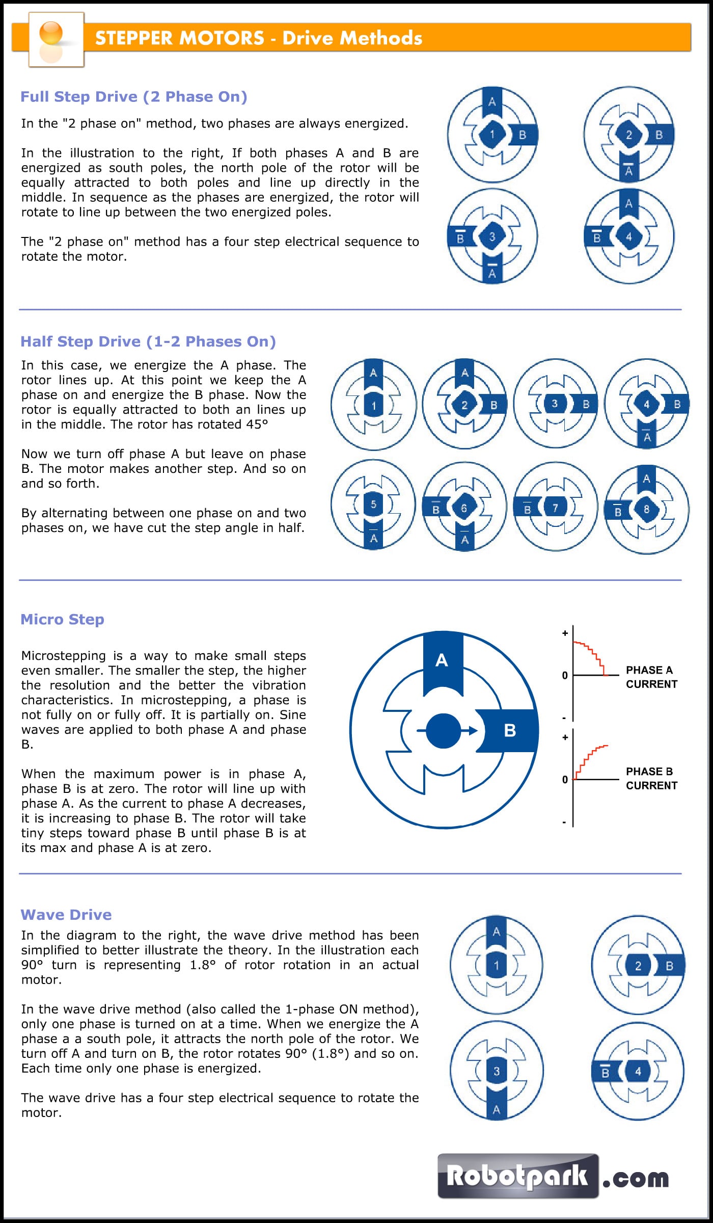
I used the wave drive mode, where at any moment only one phase is active. The microcontrollers used to turn on switches in sequence A, B, A’, B’ to rotate in CCW direction, and to reverse direction (CW) the sequence B’, A’, B, A is used.

RPM: Speed of Rotation
Motor speed of rotation is controlled using the delay through which a single phase is activated. The RPM is calculated as follows.
RPM = 60 / (resolution x step delay [s])
If T = 100 ms and given resolution = 48 steps/rev then RPM = 12.5 RPM
Stepper Motor driver
To drive the motor, I used NDS355AN N-Channel MOSFET to control each phase. The PCB designed with 1x6 headers to be connected to motor and to the ATtiny44 Development Board. The input voltage is +12 VDC through 2.1 mm jack. The development board is supplied with +5 VDC from the FABTinyISP programmer and has a common GND with stepper board.
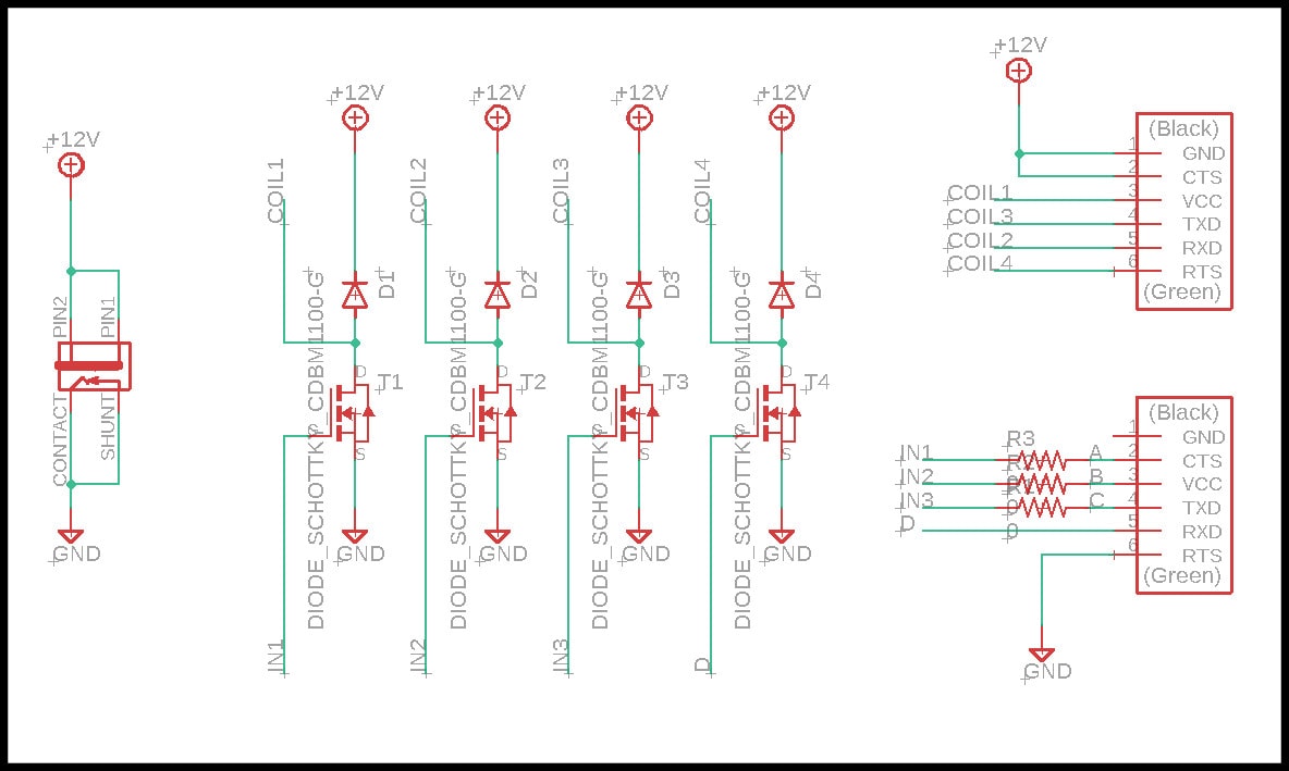
Note that I added 4 flyback diodes parallel to stepper windings and in reverse direction. “A flyback diode is a diode connected across an inductor used to eliminate flyback, which is the sudden voltage spike seen across an inductive load when its supply current is suddenly reduced or interrupted” Source
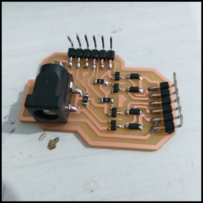
Image below shows the PCB board, traces and interiors.

This is the stepper board after welding
The code
The code define a function to move the stepper one step from the last position in CW or CCW. This function is used in two functions that can be used to move the stepper CW or CCW a given number of steps. Finally, another two functions are defined to move the stepper CW or CCW a given number of rotations. Step delay is controlled by the global variable T, which is initiated to 25 ms.
#include <avr/io.h>
#include <util/delay.h>

#define dirPort DDRA
#define dataPort PORTA
#define coil1 PA0
#define coil2 PA1
#define coil3 PA2
#define coil4 PA3

const char T = 25; //delay between steps in ms
char lastStep;

void moveStep(char, char);
void stepCW(unsigned int); //move in steps CW
void stepCCW(unsigned int); //move in steps CCW
void revCW(unsigned int); //move in revolutions CW
void revCCW(unsigned int); //move in revolutions CCW

int main(void) {
    //Clock divider set to one using lfuse bit CKDIV8 = 1

    //Unipolar, wave drive mode, 48 steps per rev
    //Stepper SM-E040 wiring. Power to Brown wires


    dirPort |= (1 << coil4); //1 Orange
    dirPort |= (1 << coil3); //2 White
    dirPort |= (1 << coil2); //3 Blue
    dirPort |= (1 << coil1); //4 Pink

    dataPort &= ~(1 << coil4) & ~(1 << coil3) & ~(1 << coil2) & ~(1 << coil1);
    dataPort |= (1 << coil1);
    lastStep = 1;


    while(1){
        revCW(2); //2 rotations CW
        _delay_ms(1000);

        revCCW(1);  //1 rotations CCW
        _delay_ms(1000);

        stepCCW(24); //24 steps CCW
        _delay_ms(1000);

        stepCW(12); //24 steps CW
        _delay_ms(1000);

        stepCCW(36); //36 steps CCW
        _delay_ms(1000);
    }
}

void revCW(unsigned int rev){
    stepCW(rev * 48);
}

void revCCW(unsigned int rev){
    stepCCW(rev * 48);
}

void stepCW(unsigned int stps){
    unsigned int i;
    for(i = 0; i < stps; i++){
        moveStep(lastStep, 1);
        _delay_ms(T);
    }
}

void stepCCW(unsigned int stps){
    unsigned int i;
    for(i = 0; i < stps; i++){
        moveStep(lastStep, 0);
        _delay_ms(T);
    }
}

void moveStep(char lstStep, char dir){
    if(dir == 0){ //CCW
        switch(lstStep){
            case 1:
                dataPort &= ~(1 << coil1); dataPort |= (1 << coil2); lastStep = 2; break;
            case 2:
                dataPort &= ~(1 << coil2); dataPort |= (1 << coil3); lastStep = 3; break;
            case 3:
                dataPort &= ~(1 << coil3); dataPort |= (1 << coil4); lastStep = 4; break;
            case 4:
                dataPort &= ~(1 << coil4); dataPort |= (1 << coil1); lastStep = 1; break;
        }
    }
    else{ //CW
        switch(lstStep){
            case 1:
                dataPort &= ~(1 << coil1); dataPort |= (1 << coil4); lastStep = 4; break;
            case 2:
                dataPort &= ~(1 << coil2); dataPort |= (1 << coil1); lastStep = 1; break;
            case 3:
                dataPort &= ~(1 << coil3); dataPort |= (1 << coil2); lastStep = 2; break;
            case 4:
                dataPort &= ~(1 << coil4); dataPort |= (1 << coil3); lastStep = 3; break;
        }
    }
}
Hero Shoot!
Week Assignment Part 2 (Extra Material): Code Test Using Breadboard
File Download
Darlington transistor array uPA1428A
To test the code, I built the same circuit using a breadboard and darlington transistor array (uPA1428A) to replace the MOSFETs.
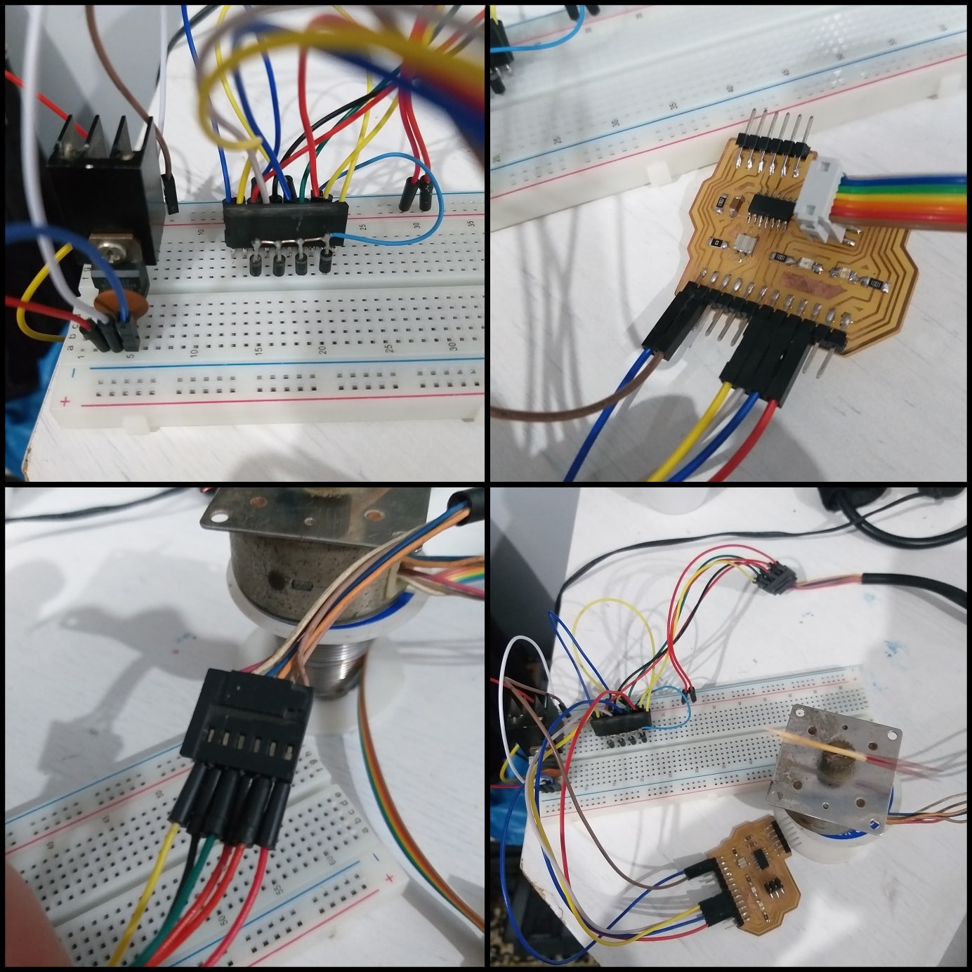
The test code will move the stepper 2 rotations CW, 1 rotations CCW, 24 steps CCW, 12 steps CW and finally 36 steps CCW.