Networking and communications
1. Weekly Brief Summary
This week, I wrote a program to serialize two Arduinos.
The first program I created is a program that turns on the 13-pin LED of Arduino at the same time.
Next, I made a program to move the servo motors at the same time.
However, these programs alone were not enough to confirm serial communication, so I decided to control the circuit of the stepper motor created in week 11 by serial communication.
The board design will be made in the Final Project work.
The details are documented in the Final Project page.
2. Weekly Assignment Requirement
Group assignment
- Send a message between two projects
Individual assignment
- design, build, and connect wired or wireless node(s) with network or bus addresses
Learning outcomes
- Demonstrate workflows used in network design
- Implement and interpret networking protocols and/or communication protocols
Have you
- Linked to the group assignment page
- Documented your project.
- Documented what you have learned from implementing networking and/or communication protocols
- Explained the programming process/es you used.
- Outlined problems and how you fixed them
- Included design files (or linked to where they are located if you are using a board you have designed and fabricated earlier) and original code.
3. Group Assignment Link
Kamakura Group Assignment Week14
4. Description of Assignment Work
Arduino Serial Communication
Serial communication is a communication method that transfers data consisting of multiple bits one bit at a time.
At this time, only one signal line is used.
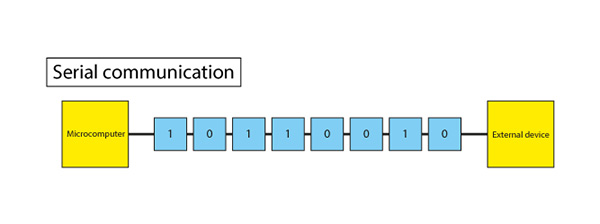
In the case of microcomputers, serial communication is often installed to reduce the number of pins used for communication.
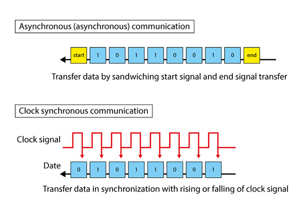
Also, for serial communication, use the start and end signals instead of the clock signal.
Asynchronous (asynchronous) communication and clock synchronous communication that synchronizes with a clock signal are available.
For the program that makes Arduino serial communication, refer to this link(JPN).
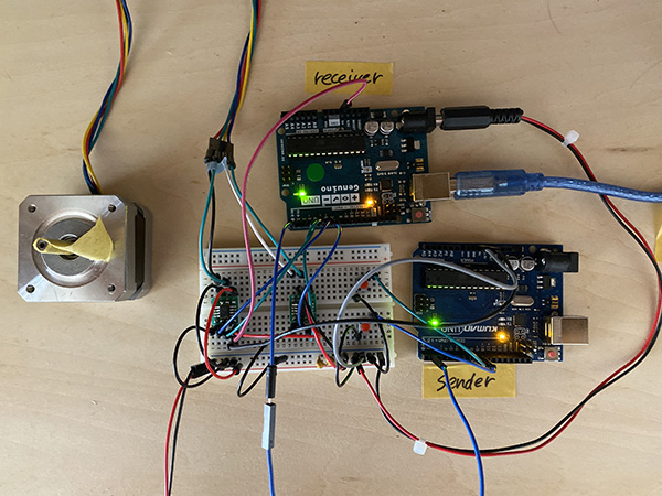
Then I connected the two Arduinos as shown in the image.
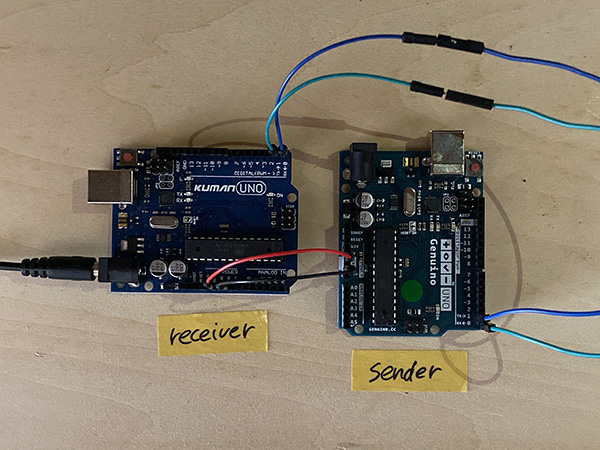
I connected the TX on the sending side to the RX on the receiving side and the RX on the sending side to the TX on the receiving side.
① Create a Sender Program
First, I created the sender program.
int LED = 13;
int count = 0;

void setup(){
  Serial.begin(9600);
  pinMode(LED, OUTPUT);
}

void loop(){
  count++;
  Serial.write(count);
  if((count % 2) == 1){
    digitalWrite(LED, HIGH);
  }else{
    digitalWrite(LED, LOW);
  }
  delay(1000);
}
| code name | meaning |
|---|---|
| int | int is a variable. A variable is a box (case) that can be freely set to give instructions (processing) to a computer. The numbers fit in the box. |
| int x = 1; | Instructed to use the box named x. And it is set to put the number “1” in the box. |
| int LED = 13; | It is instructed to put the number “13” in the LED box. That is, it represents “LED connected to digital pin 13.” |
| int count =0; | The numbers are set to start from 0. |
| Serial.begin(speed) | Specify the data transfer rate of serial communication in bps (baud). bps is bits per second. When communicating with your computer, choose one of the following rates: 300, 1200, 2400, 4800, 9600, 14400, 19200, 28800, 38400, 57600, 115200 |
| void setup(){ } | Write a directive in {} that will be executed only once when the sketch is executed. |
| pinMode( pin , mode ) | The “pinMode () function” sets a pin as either an input or an output. Specify the pin number you want to set and the INPUT or OUTPUT constant (operation). When set to INPUT, the pin can sense the state of a sensor such as a push button. When set to OUTPUT, you can drive an actuator such as an LED. |
| pinMode(LED, OUTPUT) | The LED (that is, the 13-pin LED) is set to output (light up). |
| void loop(){ } | Write the directive to be repeatedly executed in {}. A program that repeats after “void setup () {}” is executed. |
| X ++; | Instruction to add 1 to variable X |
| X ーー; | Instruction to subtract 1 from variable X |
| example | x = 2; y = ++ x; // Result: x is 3, y is 3 y = x–; // Result: x returns to 2, y remains 3 |
| count++; | Since count = 0 was set earlier, add 1 to 0 Since it is in a void loop, keep adding 1 to 0 |
| Serial.write(count) | Binary data (general data that can be handled by a computer or data other than text data (data containing only characters)) is output to the serial port. It is possible to send 1 byte at a time or multiple bytes.If you want to send it as a character (representing a number), use print (). The number in count is transmitted and Serial.write becomes (1) and is transmitted. |
| if (val == HIGH) | Although there is val == HIGH, “==” is an instruction (operator) that checks whether the values on the left and right sides are equal. ※One equal sign, “=”, is used for substitution. |
| if((count % 2) == 1) | Condition when the remainder when count (numerical value) is divided by 2 becomes 1 |
| example | When count is 1, too much becomes 1, so the contents of “if ()” are executed → LED is lit or When count is 2, it becomes 0, so the contents of “eles ()” are executed → LED goes out. ↓ In other words, when the content of count becomes an odd number, the LED lights up. |
| delay(1000) | When the program goes to the bottom, it will be stopped for 1 second and run from the top again. |
② Create a Receiver Program
Next, I created the receiver program.
int LED = 13;

void setup(){
  Serial.begin(9600);
  pinMode(LED, OUTPUT);
}

void loop(){
  while(Serial.available()){
    byte inChar = (byte)Serial.read();
    if((inChar % 2) == 1){
      digitalWrite(LED, HIGH);
    }else{
      digitalWrite(LED, LOW);
    }
    delay(10);
  }
}
| code name | meaning |
|---|---|
| int LED = 13; void setup( ) Serial.begin(9600);pinMode(LED, OUTPUT); |
Same settings as sender. |
| while( ) | “while” is used for repeated processing. The process is repeated indefinitely until the expression inside the parentheses becomes false (boolean constant = 0). The variable used in the conditional expression must be changed by adding a value or reading the sensor value in the “while” loop. Otherwise, you will not be able to get out of the loop. This confirms whether some data has arrived from the sender via serial communication. |
| Serial.available() | Returns how many bytes of data have arrived at the serial port. The number of bytes already stored in the buffer (variable for temporarily storing data). The buffer can hold up to 64 bytes. React if something comes back ↓ In this case, the program that sends the data as it is is repeated endlessly. |
| byte inChar = (byte)Serial.read() | The byte type stores 8-bit numbers from 0 to 255. It is an unsigned data type, which means it cannot handle negative numbers. In this case, I declare it as a byte type and assign 18 to it. InChar on the right side represents a binary number. |
| inChar | ≒ count |
| delay(10) | When the program goes to the bottom, it will be stopped for 0.01 seconds and run from the top again. |
When I wrote the program to two Arduinos, I confirmed that the 13-pin LED was blinking at the same timing.
Serial Communication
Servo Motor Serial Communication
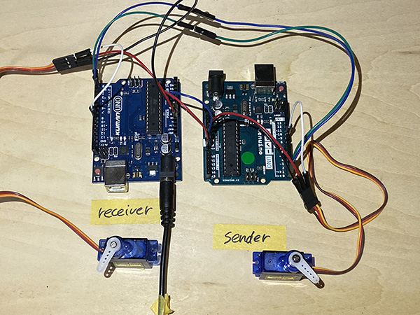
Next, I created a program that controls two servo motors by serial communication.
① Create a Sender Program
First, I created the sender program.
#include <Servo.h>

int SRV = 9;

Servo myservo;

void setup(){
  Serial.begin(9600);
  pinMode(SRV, OUTPUT);
}

void loop(){
  while(Serial.available()){
    byte inChar = (byte)Serial.read();
    if((inChar % 2) == 1){
    myservo.attach(9);
    myservo.write(0);
    delay(500);
    myservo.write(180);
    delay(500);
    }
  }
}
② Create a Receiver Program
Next, I created the receiver program.
#include <Servo.h>

int SRV = 9;
int count = 0;

Servo myservo;

void setup(){
  Serial.begin(9600);
  pinMode(SRV, OUTPUT);
}

void loop(){
  count++;
  Serial.write(count);
  while(Serial.available()){
    if((count % 2) == 1){
    myservo.attach(9);
    myservo.write(0);
    delay(500);
    myservo.write(180);
    delay(500);
    }
  }
}
When I wrote the program to two Arduinos, I confirmed that the servo motors connected to the 9-pin each rotated.
However, when I was told [rotating at the same time], I didn’t feel that the movements were deterministic, so I decided to write a program to control another Output device via serial communication. did.
Serial Communication
Stepper Motor Serial Communication
I created a program that controls the button switch with the sending Arduino and controls the stepper motor with the receiving Arduino.
① Create a Sender Program
First, I created the sender program.
#include <Stepper.h>

const int stepsPerRotate = 200;//Number of Steps = 360 / Step Angle = 360 / 7.5 = 48
Stepper myStepper(stepsPerRotate, 4, 6, 5, 7);

int oldsw1=1;
int oldsw2=1;

void setup(){
  pinMode(8,INPUT_PULLUP);
  pinMode(9,INPUT_PULLUP);

  Serial.begin(9600);

}

void loop(){
  int sw1=digitalRead(8);
  int sw2=digitalRead(9);

  if(oldsw1!=sw1){
    Serial.print("#1=");
    Serial.println(sw1);
  }

  if(oldsw2!=sw2){
    Serial.print("#2=");
    Serial.println(sw2);
  }
  oldsw1=sw1;
  oldsw2=sw2;


  //myStepper.setSpeed(50);
    //if(sw1==LOW){
     // myStepper.step(10);
    //}
    //else if(sw2==LOW){
      //myStepper.step(-10);
    //}
    //else{
      //myStepper.step(0);
   // }
  delay(50);
}
② Create a Receiver Program
Next, I created the receiver program.
#include <Stepper.h>

const int stepsPerRotate = 200;//Number of Steps = 360 / Step Angle = 360 / 7.5 = 48
Stepper myStepper(stepsPerRotate, 4, 6, 5, 7);

char RXbuf[5];
int RXcount=0;
int RXsw=0;
char RXdata;
int sw1=1;
int sw2=1;

void setup(){
  pinMode(8,INPUT_PULLUP);
  pinMode(9,INPUT_PULLUP);
  Serial.begin(9600);
  }

void loop(){
  //int sw1=digitalRead(8);
  //int sw2=digitalRead(9);
  //Serial.print("#1=");
  //Serial.println(sw1);
  //Serial.print("#2=");
  //Serial.println(sw2);

  if(Serial.available()>0){
    RXdata=Serial.read();
    if(RXsw==0){
      if(RXdata=='#'){
      RXsw=1;
      RXcount=1;
      }
    }
    else{
      RXbuf[RXcount]=RXdata;
      if(RXcount==3){
        RXsw=0;
        if (RXbuf[1]=='1'){
          if (RXbuf[3]=='0'){
            sw1 = 0;
         }else{
            sw1 = 1;
         }
       }
        if (RXbuf[1] == '2'){
          if (RXbuf[3] == '0'){
            sw2 = 0;
          }else{
            sw2 = 1;
          }
        }
      }
      RXcount++;
    }
  }
    myStepper.setSpeed(50);
    if(sw1==LOW){
      myStepper.step(10);
    }
    else if(sw2==LOW){
      myStepper.step(-10);
    }
    else{
      myStepper.step(0);
    }
}
| code name | meaning |
|---|---|
| char RXbuf[5] | Buffer to store 5 bytes of received data |
| int RXcount | Pointer to where in RXbuf to store the received data |
| int RXsw | Flag indicating whether switch data is being received |
| 0 | Waiting for’#’ |
| 1 | Receiving data |
| char RXdata | Place to store received data |
| Contents of RXbuf (after receiving) RXbuf[0]→‘#’ RXbuf[1]→‘1’(スイッチ番号) RXbuf[2]→‘=’ RXbuf[3]→‘0’(Switch status) |
#1=0(Leave the data area for line breaks)=[5]) |
| Serial.available() | An instruction that only indicates whether it has been received |
| Serial.Read | Instruction to read the received data |
| int RXdate | Save the data read once |
| sw1=0 | Switch is pressed |
| sw1=1 | The switch is not pressed |
**char**

A type that consumes 1 byte of memory to store one character. Characters are written by enclosing them in single quotation, such as'A' (when multiple characters = character string, use double quotation, such as "ABC").

Characters are stored as numbers. This means that you can treat characters as objects of calculations. For example, the uppercase A in the ASCII code is 65, so'A'+1 becomes 66. The conversion of characters to numbers is explained in more detail in the Serial.print section.

The char type is a signed type and is treated as a number from -128 to 127. If you need one unsigned byte, use the byte type.

【Example】
char myChar = 'A';
char myChar = 65;   // Same meaning
Serial Communication
Serial Monitor
Final Project Networking & Communications Board Design
The earring and the obi-dome that I made in Final Project control the way Neopixel glows by infrared communication. I built an infrared receiver in the earring side and an infrared transmitter in the obi-dome side.
Verification of Infrared Receiver in Breadboard Circuits
The verification of the infrared receiver in the breadboard circuit is described in Breadboard Prototyping & Programming on the Final Project page.
Validation of Infrared Transmitters in Breadboard Circuits
The verification of the infrared transmitter in the breadboard circuit is described in Breadboard Prototyping & Programming on the Final Project page.
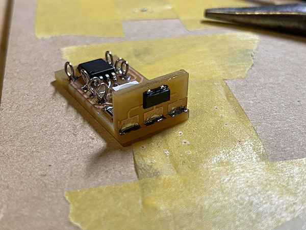
Infrared receiver board design
The board design of the infrared receiver is shown in Circuit Design & Board Design at EAGLE on the Final Project page.
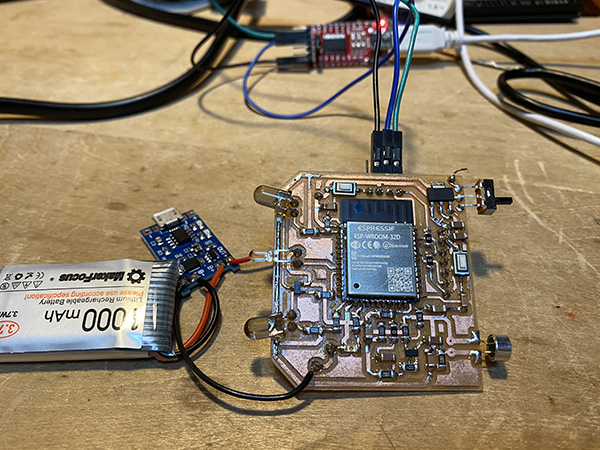
Infrared transmitter board design
The board design of the infrared transmitter is shown in Circuit Design & Board Design at EAGLE on the Final Project page.
Infrared receiver board production
Please refer to Erectronics Production & Embedded Programming on the Final Project page for the infrared receiver board.
Infrared transmitter board production
Please refer to Erectronics Production & Embedded Programming on the Final Project page for more information on the manufacturing of the infrared transmitter board.
Infrared communication
I have confirmed that the two devices are working as programmed through infrared communication.
5. Description of Important Weekly Learning Outcome
This time, I created a program that uses two Arduinos for serial communication.
At first, I tried to record this using a servo motor, but decided that it was difficult to understand how serial communication was performed.
Therefore, I diverted the circuit that controls the stepper motor used in Week 11 with a button switch, and controlled the button switch with the Arduino on the sender side, and the circuit that rotates the stepper motor controlled by the Arduino on the receiver side when the button is pressed.
I created a program.
It turns out that this circuit inevitably causes a time lag because the motor rotates after receiving the information when the switch is pressed.
I was able to understand that the method of controlling by serial communication is not a good idea to realize real-time reaction.
6. Links to Files and Code
- LED serial_reciver [ino]
- LED serial_sender [ino]
- Servo serial_reciver [ino]
- Servo serial_sender [ino]
- Stepper serial_reciver [ino]
- Stepper serial_sender [ino]
7. Appendix
None