Output devices
1. Weekly Brief Summary
I built a pair of Neopixel-powered earrings for the Final Project. The process of making this device is described in Final Project output device board design.
This week I created a circuit for a stepper motor to be used in FinalProject.
Since the lab is closed due to the coronavirus, I worked on the breadboard.
In the first half of the assignment, I can’t write the program to the board with ATtinny45 It wasn’t.
Then, assuming the final project, I used an Arduino to create a stepper We have created the circuit and program to control the motor.
The board design will be made in the Final Project work.
The details are documented in the Final Project page.
2. Weekly Assignment Requirement
Group assignment
- Measure the power consumption of an output device
- Document your work (in a group or individually)
Individual assignment
- Add an output device to a microcontroller board you’ve designed and program it to do something
Learning outcomes
- Demonstrate workflows used in controlling an output device(s) with MCU board you have designed
Have you
- Linked to the group assignment page
- Documented how you determined power consumption of an output device with your group
- Documented what you learned from interfacing output device(s) to microcontroller and controlling the device(s)
- Described your design and fabrication process or linked to previous examples.
- Explained the programming process/es you used
- Outlined problems and how you fixed them
- Included original design files and code
- Included a ‘hero shot/video’ of your board
3. Group Assignment Link
Kamakura Group Assignment Week11
4. Description of Assignment Work
Creating a Remote Work Environment
FabLab Kamakura closed until May 6th following the Japanese government’s declaration of emergency.
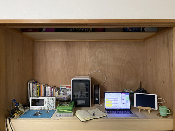
So, I got a loan from FabLab Kamakura to 3D printers, oscilloscopes, and other equipment necessary to advance Fab Academy’s assignments.
There was no space in my room to place these equipment, so I set up a HomeLab in a “OSHI-IRE” (Japanese style closet).
I’m currently working in this space.
Circuit Design using ATtiny44
① Soldering
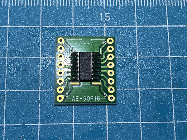
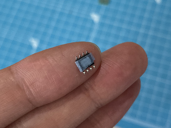
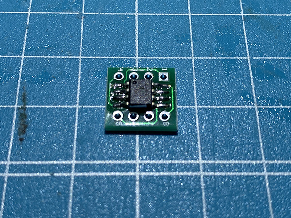
First time, I soldered the ATtiny44 and the motor driver to the breakout board.
The number of pins on the ATtiny44 and the Breakout board is not the same, but solder from the top.
I have also attached masking tape to the back of the motor driver to prevent short circuiting.
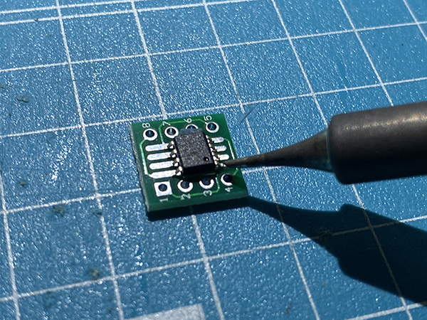
Then I soldered the pin header and board and put them on the breadboard.
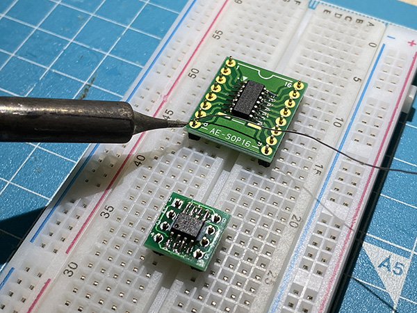
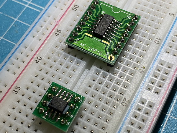
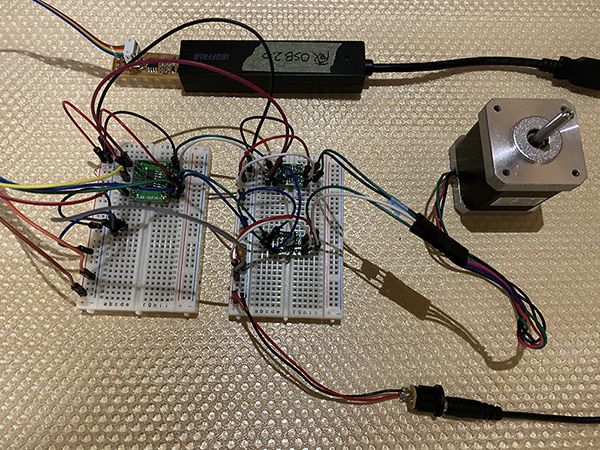
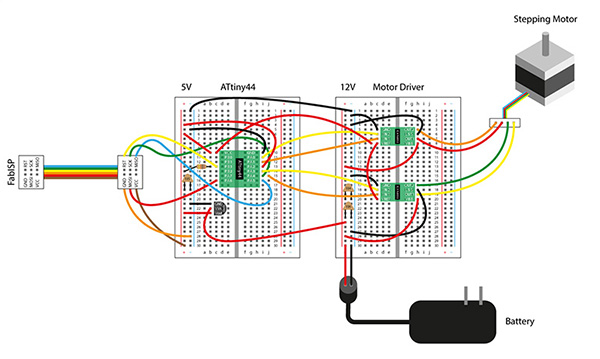
② Eproduce a Sample Circuit on a Breadboard
I will create a 3D printer with FinalProject, so this sample circuit I chose this time is “steper motor’s bipolar”.
I wired while checking the board design.
↓
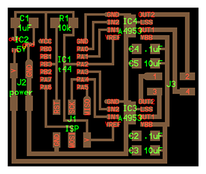
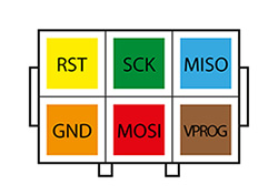
I drew the placement of the FabISP pin headers and the circuit I created in 2D in order to understand this wiring myself.
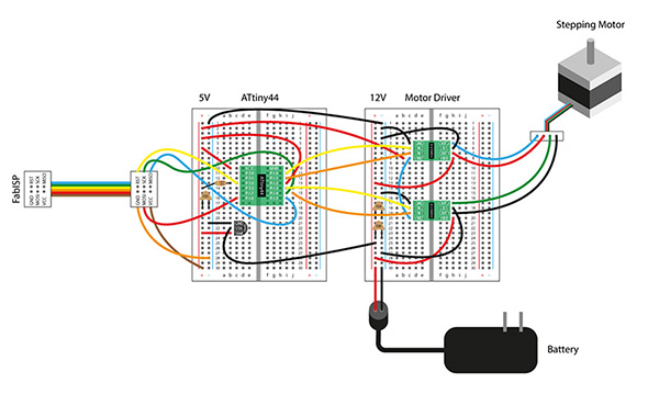
Why is pin PA2 connected to 5V ?
It is a Neil trick that PA2 is connected to + 5V. It is needed to connect VREF of IC4 to + 5V, but routing is difficult, so Neil is just connecting it to + 5V via the land of PA2 which is not used in the program. Since no PA2 is set in the program, it has no effect because it is set to the input port by default and + 5V is connected.
Programming
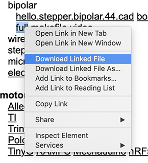
① Download makefile
Download the make file for “stepper motor - bipolar” from here.
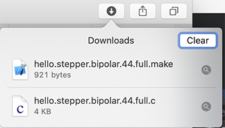
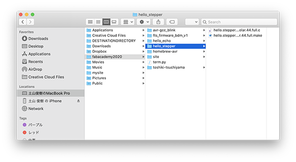
I created a folder called “hello_stepper” and saved it.
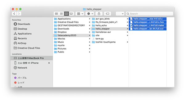
Ran [$ make -f hello.stepper.bipolar.44.full.make] on Terminal.
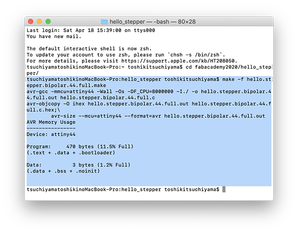
The compilation was successful.
Ran [$ sudo make -f hello.stepper.bipolar.44.full.make program-usbtiny] on Terminal.
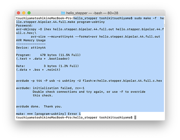
The message Error 1 appears and the program failed to write.
So I looked into what the problem was.
② Finding and Debugging Problems
To Do List
(1)Checking for Power
(2)Verifying the Wiring
(3)Checking FabISP Contact
(1)Checking for Power
I checked with a tester to see if the circuit has power.
So I found out that the GND of ATtiny44 is not connected.
I have also corrected the 2D circuit diagram.
(2)Verifying the Wiring
When I checked the circuit, I corrected the VBB of IC4 A4953 because it was connected to GND instead of VCC.
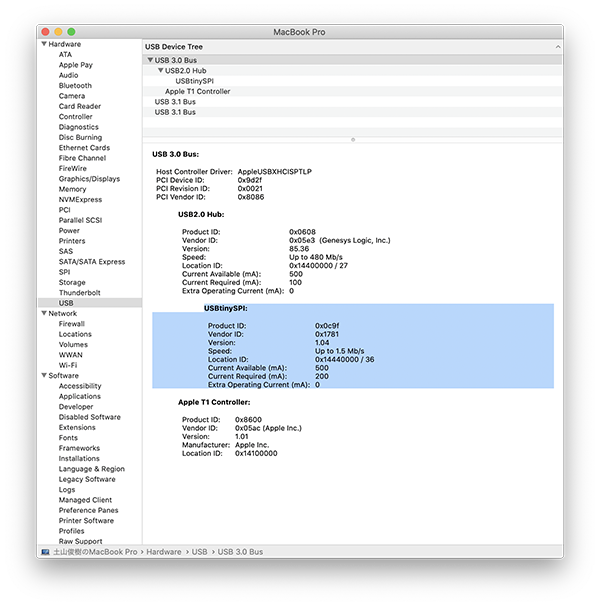
(3)Checking FabISP Contact
I didn’t check if the PC recognized FabISP.
However, I found out that it was recognized by the PC side without any problems.
Circuit Change
This time, I gave up using this circuit to operate the motor.
The reason is that it may take a long time to debug.
So I decided to give priority to moving the motor over debugging.
Circuit Design using Arduino UNO
The work from here is done before “Circuit Design using ATtiny44-② Finding and Debugging Problems” in time series.
“hello.stepper.bipolar.44” using ATtiny44 is a circuit for understanding the principle of stepper motor.
In addition, this circuit can control only one G code and stepper motor capacityally.
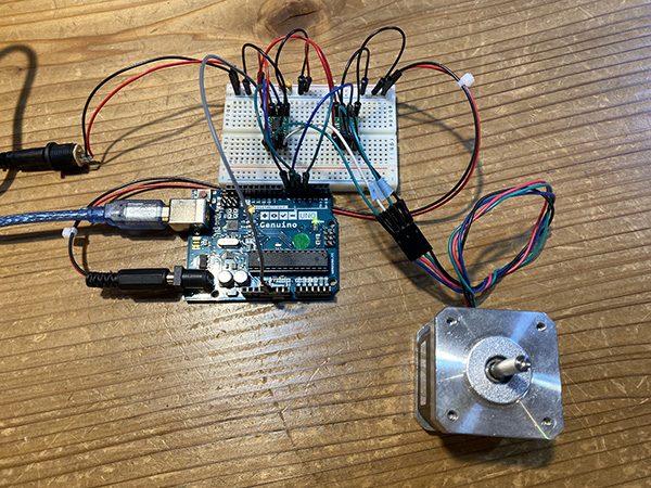
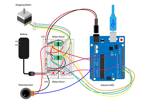
So I decided to use Arduino UNO to create a circuit for Final Project.
Also, I plan to create a satshakit based on the created circuit and the integrated program.
- Mechanism of “hello.stepper.bipolar.44”
It can’t be used in the final project.
↓ - Mechanism of “Arduino UNO and stepper motor”
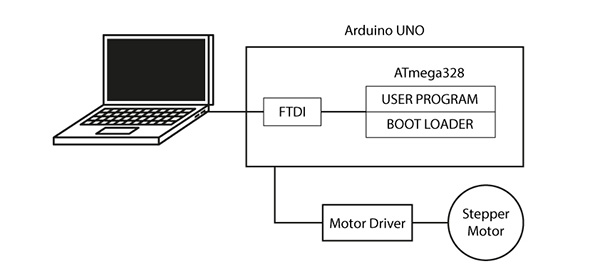
ATmega328 = 32KB (ROM:Program Space) / 8KB (RAM:Work Memory Space)
BOOT LOADER = Ability to write programs
Arduino’s Libraries have a lot of control programs and is guaranteed to work.
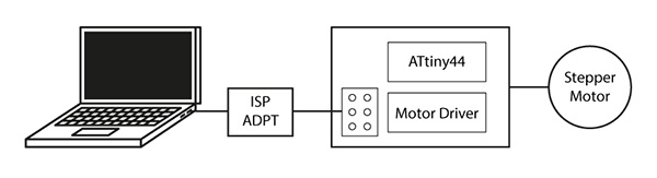
↓ - Mechanism of “Satshakit and stepper motor”
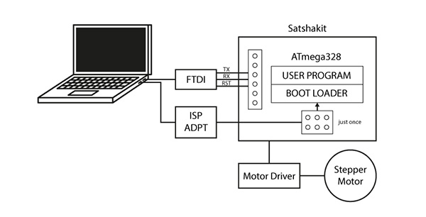
Use ATmega328’s flat package.
Use the ISP adapter to write to BOOT LOADER only once.
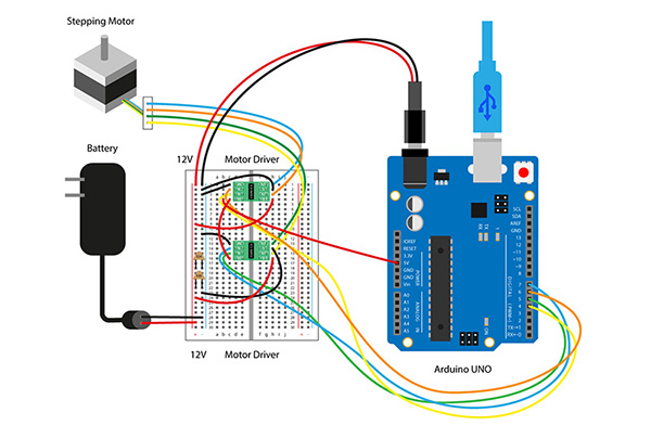
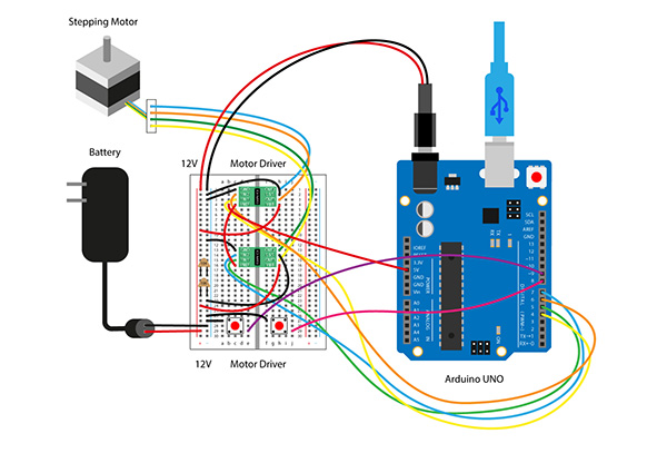
① Use Arduino UNO to Operate Stepper Motor
There are two types of stepper motor : unipolar and bipolar.
I will make a 3D printer for the final project, so this time I decided to use stepper motor of bipolar.
-
Mechanism of “Unipolar”
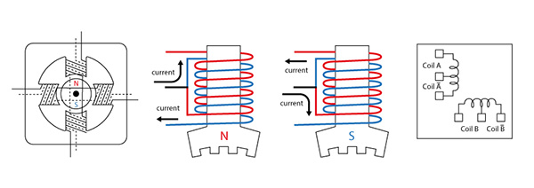
The Stepper Motor in unipolar is controlled by approximately five to six signal lines.
This motor is easy to control but has weak power. -
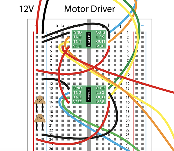
Mechanism of “Bipolar”
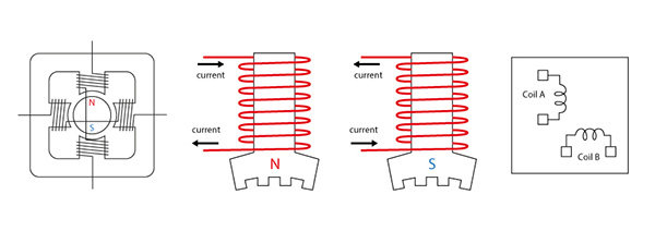
The Stepper Motor in bipolar is controlled by four signal lines.
This motor is difficult to control but powerful.
② Programming
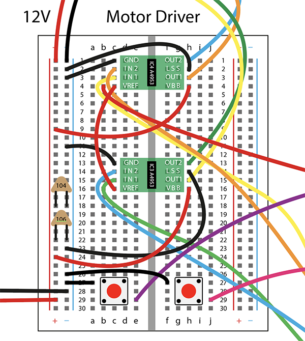
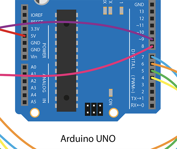
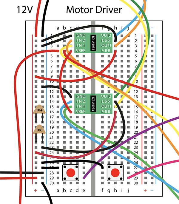
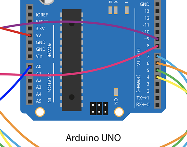
I removed the jumper from the ATtiny44 side breadboard and connected the motor driver side breadboard and Arduino UNO.
First, I used a library to drive a stepping motor called Stepper.h.
Next, I changed the value to “myStepper.step(200)” to match the number of steps of the motor to be used.
#include <Stepper.h>

const int stepsPerRotate = 200;//Number of Steps = 360 / Step Angle = 360 / 7.5 = 48
Stepper myStepper(stepsPerRotate, 4, 6, 5, 7);

void setup(){

}

void loop(){
  myStepper.setSpeed(15);
  myStepper.step(200);
  delay(500);
  myStepper.step(-200);
  myStepper.setSpeed(30);
  myStepper.step(200);
  delay(500);
  myStepper.setSpeed(50);
  myStepper.step(-200);
  delay(500);
  myStepper.setSpeed(80);
  myStepper.step(200);
  delay(500);
}
| code name | meaning |
|---|---|
| myStepper.step myStepper.step(200) |
an instruction that indicates how many revolutions a step by step The motor I used this time is 200 steps per rotation, so it is exactly one rotation. |
| myStepper.setSpeed myStepper.setSpeed(15) |
the speed expressed in rpm (number of revolutions per minute) 15 rpm rotates 15 revolutions per minute, or 1 revolution in 4 seconds. |
| delay delay(500) |
Stops the program for a specified amount of time.The unit of time is milliseconds.(1 second = 1000 milliseconds) Stop the program for 0.5 seconds. |
Save the downloaded folder under [ Documents ]→[ Arduino ] → [ Libraries ]. ※ For Mac
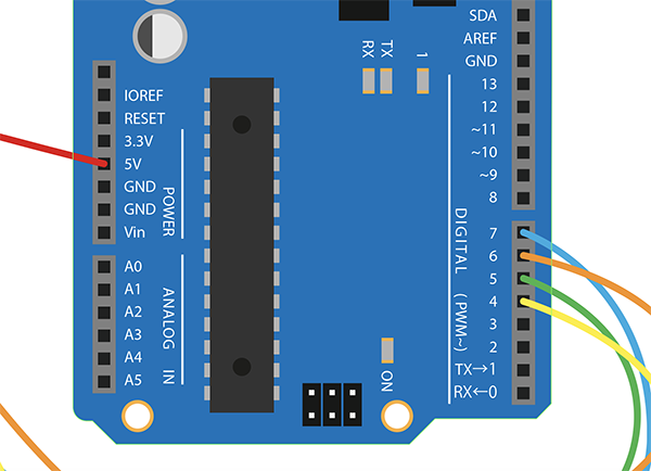
Referred to “Stepper myStepper(stepsPerRotate, 4, 6, 5, 7);” in “Stepper.h” and connected the digital pin of Arduino UNO to the input pin of the motor driver.
I also used “Watasi Stepper Motor: 42BYGHM809”.
[ Datasheet ]
↓
However, I wrote the program to Arduino, but stepper motor didn’t work properly.
③ Finding and Debugging Problems
To Do List
(1)Check the control signal from the microcomputer
(2)Check motor-side control signals
(3)Re-soldering
(4)Replacing the Motor Driver
(5)Replacing the Stepper Motor
(1)Check the control signal from the microcomputer
I checked the motor driver’s microcomputer control signal with an oscilloscope.
However, I was able to confirm the 5V waveform.
Therefore, there was no problem with the control signal from the microcomputer.
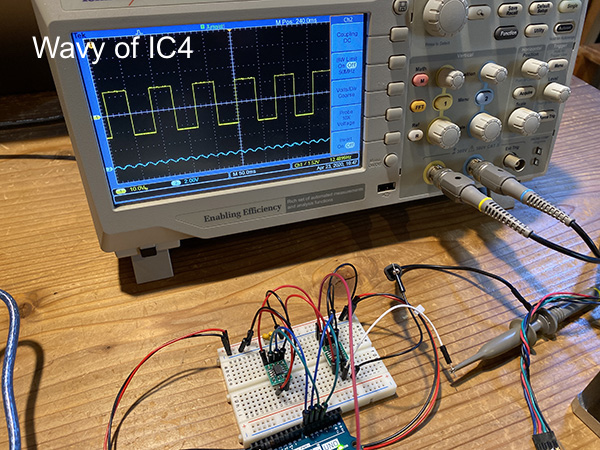
(2)Check motor-side control signals
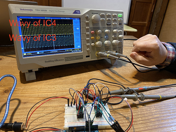
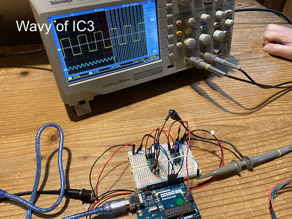
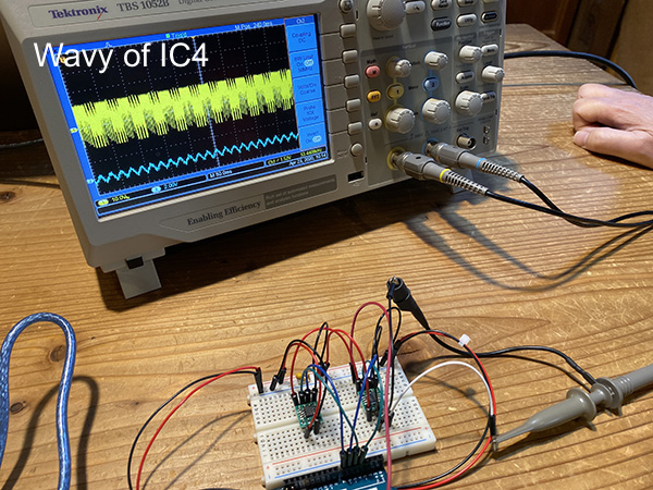
Next, I checked the motor-side control signal of the motor driver for any problems.
There was no problem with the control signal on the IC3 side, but the normal waveform could not be detected from the control signal on the IC4 side.
This may be caused by a motor driver for IC4.
(3)Re-soldering
I thought that the motor drivers on the IC4 side were not soldered enough, so I re-soldered them.
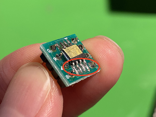
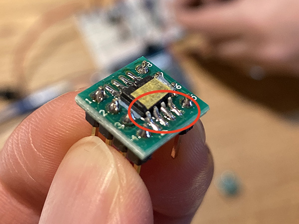
However, the motor was not working as it was before.
(4)Replacing the Motor Driver
I decided that there was a problem with the motor driver itself, so I prepared a new motor driver.
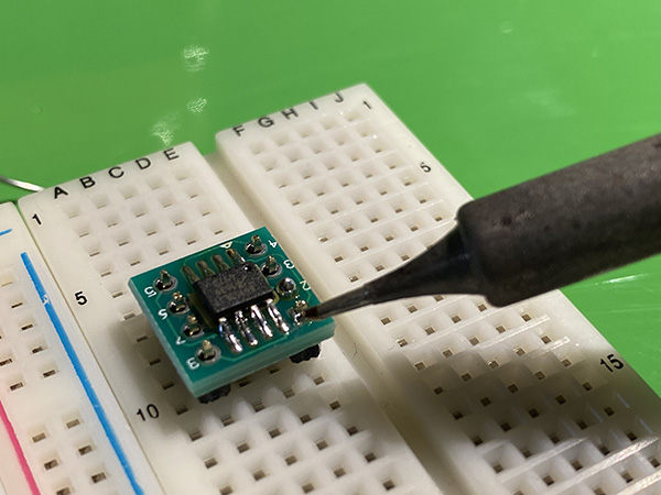
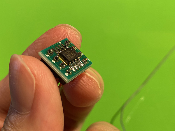
And I put the motor driver that I created in the IC4 location.
When I checked the motor side control signal, I was able to detect the normal waveform.
However, I wrote the program again, but the motor did not work.
(5)Replacing the Stepper Motor
In the end, I thought there was a problem with stepper motor.
So when I checked the coil Resistor of stepper motor on the tester, it was 1.9Ω.
So we found that there is a 6A current flowing in this circuit where there is a 12V voltage.
As a result, the voltage dropped due to excessive current flow, and the microcomputer stopped working.
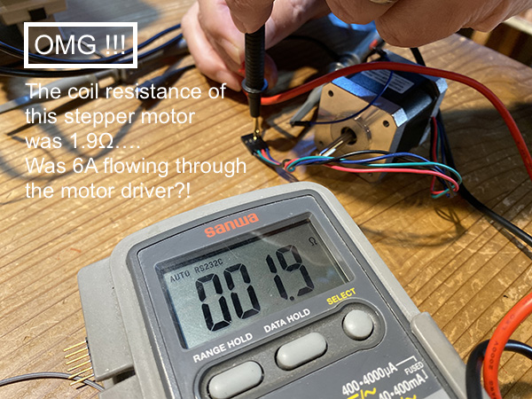
Therefore, I decided to use my own “42mm square bipolar steppermotor (coil Resistor 30Ω): model number unknown”.
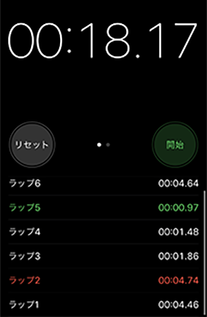
And when I turned off the power, the stepper motor worked normally.
Also, I used a stopwatch to check if stepper motor is working as planned.
④Add Other Programs
I added the following devices necessary for the extroducter to make in the final project and created a program to run them.
- Normal rotation button: Pressing the button turns the motor (extrusion of material)
- Turnaround button: When you press the button, the motor turns (filling the material)
- Potential meter: Adjust the rotational speed of the motor
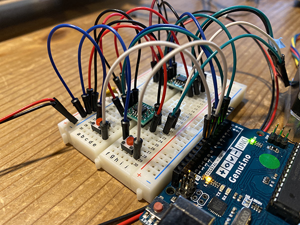
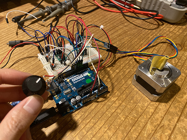
(1) Creating a Circuit with Button Added
I added a button switch to the circuit that turns the stepper motor and created a program that reverses the direction of rotation of the motor.
↓
I went on with “Stepper.h” adding a program for buttons.
| Programming | Results / Remed |
|---|---|
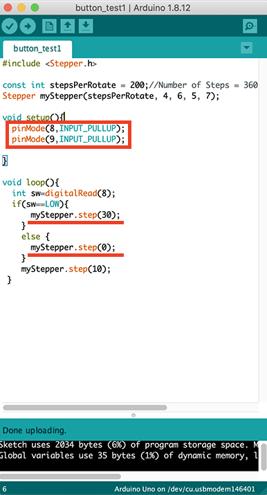 |
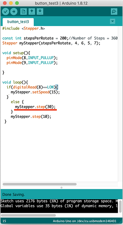
×(didn’t revolve) I tried to create a program called “When I press the button, the motor rotates at 30 rpm and when I release the button, the motor stops rotating.” So I thought setting it to “else{myStepper.setSpeed(0)}” would stop the motor. And I added the Arduino pin setting corresponding to the button switch. |
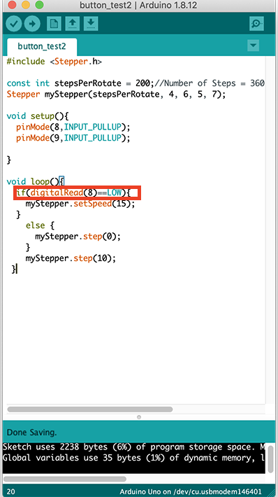 |
×(didn’t stop) I changed the part of “int sw=digitalRead(8); if(sw==LOW)” to “if(digitalRead(8)==LOW)” and wrote the program again. However, when I pressed the switch, the motor continued to spin at a speed of 15 rpm. It didn’t stop when I pushed the button again. |
 |
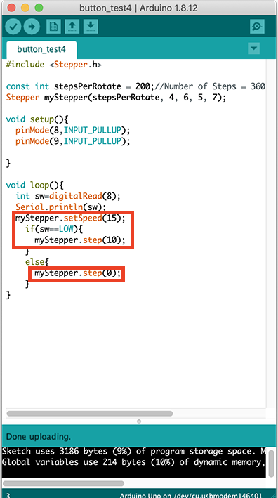
×(didn’t stop) I changed the part of “myStepper.step(0)” to “myStepper.step(30)” and wrote the program again. However, the result was exactly the same as the previous one. In other words, I found out that the code “myStepper.step(0)” is wrong. The program was not functioning properly because of this code. |
 |
○(can stop) I wrote a program in which the motor turns at 15 rpm when I press the button and the motor stops when I release the button. As a result, we were able to control the motors according to the program we created. |
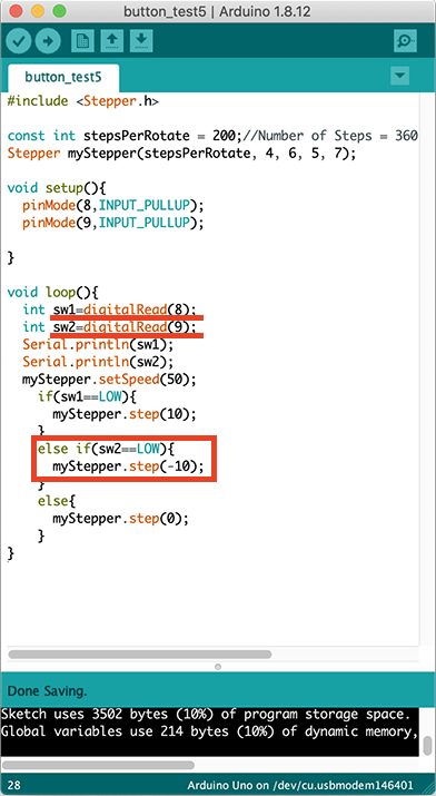 |
○(can stop & W revolve) I wrote a program that I had added another button that I made last time. At that time, I set button1 to “int sw1=digitalRead(8)” and button2 to “int sw2=digitalRead(9)”. And I was able to run the program and control the motor and button according to the program. |
#include <Stepper.h>

const int stepsPerRotate = 200;//Number of Steps = 360 / Step Angle = 360 / 7.5 = 48
Stepper myStepper(stepsPerRotate, 4, 6, 5, 7);

void setup(){
  pinMode(8,INPUT_PULLUP);
  pinMode(9,INPUT_PULLUP);

}

void loop(){
  int sw1=digitalRead(8);
  int sw2=digitalRead(9);
  Serial.println(sw1);
  Serial.println(sw2);
  myStepper.setSpeed(50);
    if(sw1==LOW){
      myStepper.step(10);
    }
    else if(sw2==LOW){
      myStepper.step(-10);
    }
    else{
      myStepper.step(0);
    }
}
(2) Creating a Circuit with Button & Potential Meter Added
I added the potentional meter to the circuit I just created and created a program that can adjust the rotational speed of the motor.
↓
#include <Stepper.h>

const int stepsPerRotate = 200;//Number of Steps = 360 / Step Angle = 360 / 7.5 = 48
Stepper myStepper(stepsPerRotate, 4, 6, 5, 7);

void setup(){
  pinMode(8,INPUT_PULLUP);
  pinMode(9,INPUT_PULLUP);
  pinMode(4,OUTPUT);
  pinMode(5,OUTPUT);
  pinMode(6,OUTPUT);
  pinMode(7,OUTPUT);
  Serial.begin(9600);
}

void loop(){
  int sw1=digitalRead(8);
  int sw2=digitalRead(9);
  //Serial.println(sw);
  int sensorReading = analogRead(A0);
  int motorSpeed = map(sensorReading,0,1023,1,100);
  myStepper.setSpeed(motorSpeed);
  if(sw1==LOW){
      myStepper.step(10);
    }
    else if(sw2==LOW){
      myStepper.step(-10);
    }
    else{
      myStepper.step(0);
      /*digitalWrite(4,LOW);
      digitalWrite(6,LOW);
      digitalWrite(5,LOW);
      digitalWrite(7,LOW);
    */}
}
| code name | meaning |
|---|---|
| map( ) map(sensorReading,0,1023,1,100) |
the function of converting a number from one range to anoth Arduino has a 10-bit AD converter (analog-to-digital conversion). This allows conversion to a number from 0 to 1023 when 0 V to 5 V is entered. |
Final Project output device board design & production
I incorporated the output device into an earring I made in Final Project. I used Neopixel. These mechanisms and programming creation are described in Breadboard Prototyping & Programming on the Final Project page. In this page, I explain the process of cutting the board by using SRM-20 after making the schematic in EAGLE.
Creating a circuit in EAGLE
Based on the breadboard circuit we created, we selected surface-mounted sensors and other components to be used.
breadboard diagram
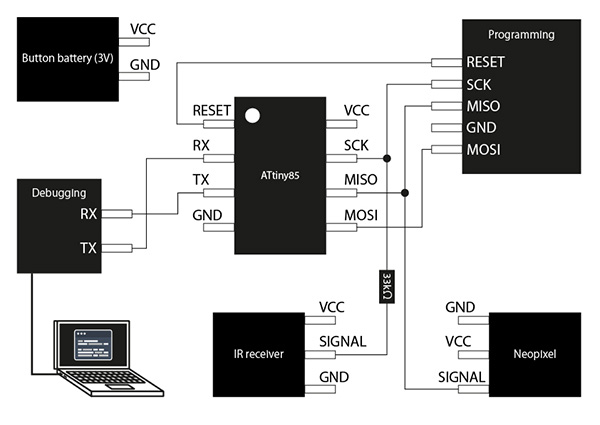
① ATtiny85
The ATtiny85 decided to use a surface-mounted [AVR microcontroller ATTINY85-20SUR].
data sheet
-
Main Specifications
| Function | Details |
|---|---|
| Power supply voltage | 2.7~5.5V |
| core size | 8bit |
| clock | 20MHz |
| GPIO | 6 pin |
footprint
I used [TINY25/45/85-20SU] in [avr-7].
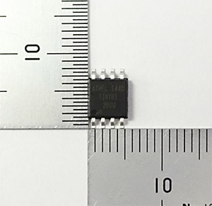
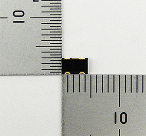
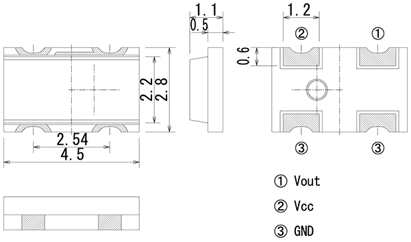
② IR Receiver
I decided to use a surface-mounted [[Remote Control Receiver Module PIC79603]] (http://akizukidenshi.com/catalog/g/gI-11734/) for the IR receiver.
data sheet
- Main Specifications
| Function | Details |
|---|---|
| Power supply voltage | 2.7~5.5V |
| Current consumption | 0.9~1.3mA |
| Peak Sensitivity Wavelength | 940nm |
| Tuning frequency | 37.9kHz |
footprint
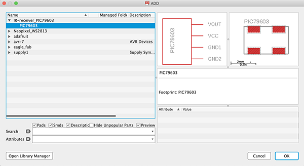
I couldn’t find the footprint of [PIC79603] on the web, so I used EAGLE to create my own [IR-receiver_PIC79603.lbr].(specified in → [Creating symbol & footprint data for the device to be used])
③ Neopixel
Neopixel decided to use the surface-mounted [RGB LED WS2813B with built-in microcontroller].
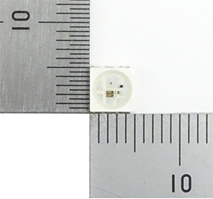
data sheet
- Main Specifications
| Function | Details |
|---|---|
| Power supply voltage | 5V(3.5V~5.3V) |
| LED | RGBLED |
| Red | 620-625nm 360mcd |
| Green | 515-525nm 1150mcd |
| Blue | 465-475nm 220mcd |
footprint
I couldn’t find a footprint for [WS2813B] on the web, so I made my own [Neopixel_WS2813.lbr] using EAGLE.
④ 33kΩ
For 33kΩ, I decided to use a surface mount [Chip Resistor 1/10W33kΩ].
datesheet
footprint
I used [R1206FAB] in [eagle_fab.lbr].
⑤ 0.1μF
I decided to use surface mount [[Chip Monolithic Ceramic Capacitors 0.1μF100V C0G 3216]] (http://akizukidenshi.com/catalog/g/gP-15180/) for the 0.1μF.
datesheet
footprint
I used [C1206FAB] in [eagle_fab.lbr].
⑥ Battery
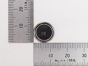
I decided to use [Lithium battery CR1220 from Golden Power] for Battery. And I used [Holder for Button Cell Substrate for CR1220 CH291-1220LF] for the battery holder.
Creating symbol & footprint data for the device to be used
I couldn’t find the symbol & footprint data for [Remote Control Receiver Module PIC79603] on the web, so I used EAGLE to create the data myself.
(1) Create a parts library in EAGLE
With EAGLE, it is necessary to store all the parts you have created in the “Library”. Even if you only have to create one part, you must always create a library.
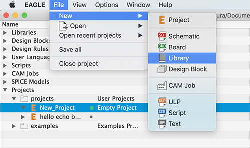
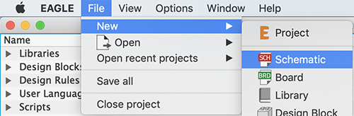
You can create a new part library from [File] - [New] - [Library].
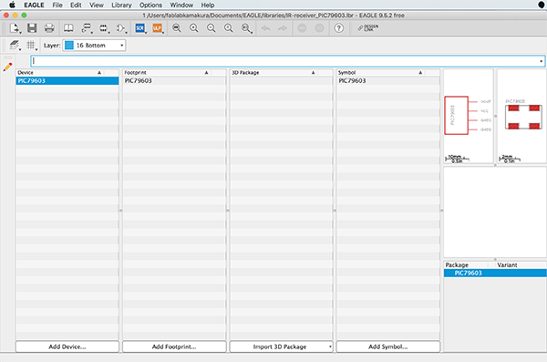
Create a new library from the EAGLE start page.
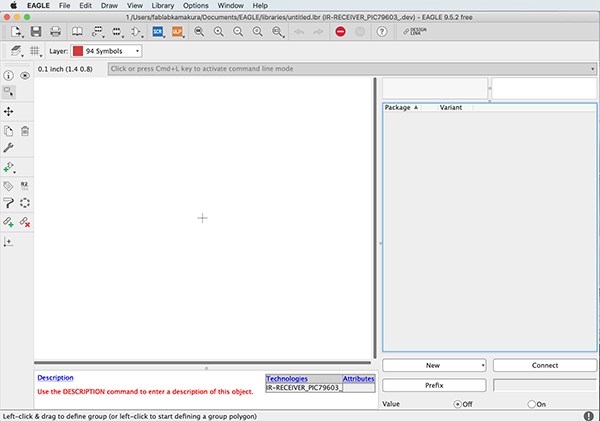
The basic page of the EAGLE library. Use this page as a basis for editing symbols, footprints, 3D data, etc.
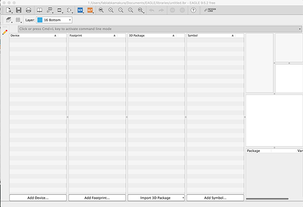
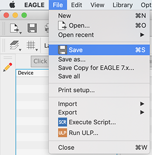
It can’t save it by just creating a new Library, so I should save it once in this screen. Save the file with a name that is easy to distinguish.
(2) Adding a part name to the parts library
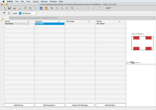
After creating the part library, you can proceed to create the part. In the Device, where you specify the part name, the symbol, footprint and 3D model associations, as well as the wiring information and part prefix information are stored.
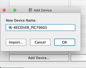
[Add Device…] in the [Device] bar on the left side of the screen and enter the product name of the part you want to register.
Click the [Add Device…] button at the bottom left to register the part name. Enter a product name that is easy to understand and press OK button.
When the registration of the parts is finished, the screen to link the parts opens. Press the “Table of contents” button on the upper left to go back to the previous screen.
(3) Create a [part symbol]
A parts symbol is a circuit symbol that appears on a circuit diagram. However, in many cases, a new symbol must be created when a special switch or microcontroller is included in a circuit diagram.
There are two main ways to create a part symbol, one is to create it from scratch and the other is to import it from another library.
In this article, we will use the “Create from scratch” method, but it is rarely necessary to create the actual symbol from scratch. In general, you can import other part symbols and adjust their shapes.
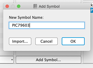
Press “Add Symbol…” at the bottom right to decide the name of the symbol. It doesn’t have to be the same name as the part we are adding, so we have to give it a name that is easy to recognize.
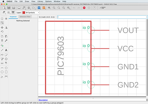
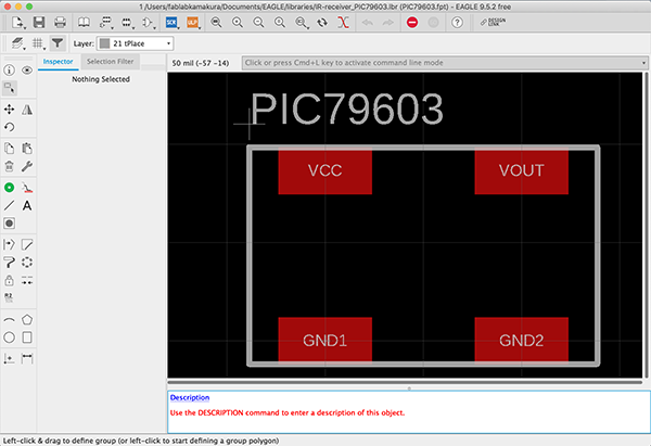
Symbol Editor opens. In this screen, make the shape and terminal of the electronic circuit. To make a rough shape, draw a shape or a line from the left menu.
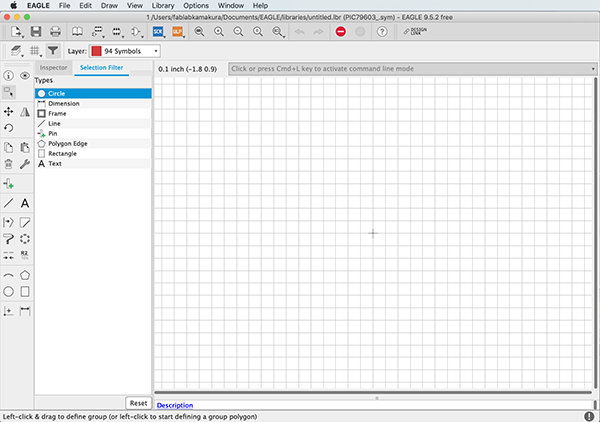
Making the PIC79603 symbols. I created a rough shape based on the PIC79603 datasheet.
It will take some time to get used to the unique way of operating it. The basic way to use this application is to adjust the position of roughly created shapes and lines by entering the coordinates.
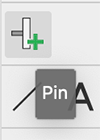
Once the overall shape is complete, set up the connection terminals. Select the “Pin” button from the left menu.
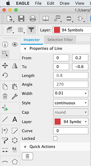
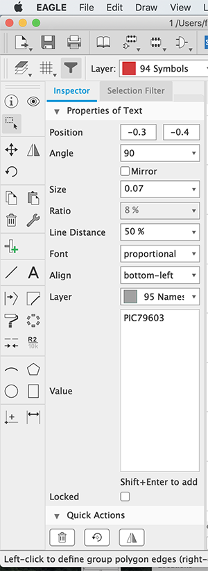
When a placed pin is selected, the shape of the pin can be adjusted from the Inspector menu. Rotation is adjusted by [Angle] element, length of pin is short by [Length] element. In this case, we don’t need the pin name, so we turn off [Visible] element.
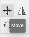
To move the pin, select [Move] from the left menu and click the pin in the move state.
This is a completed symbol, but when we place it in the schematic, it doesn’t indicate the quantity (L1, L2) and capacity of the parts. In the end, we need to specify [Text] to indicate the quantity and capacitance.
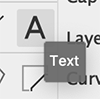
In Text, enter [>NAME] and specify [Layer] as 95 Names. With this setting, part numbers with prefixes such as L1, L2, etc. will be displayed automatically.
Save it when completed.
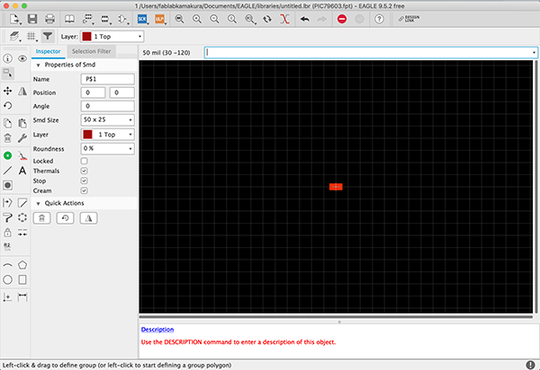
(4) Create a [footprint]
The next step is to create a footprint. In creating the footprint, we referred to the electronic component data sheet to create it. The datasheet includes a “Recommended Pattern Diagram” which we used to create the pattern.
Select [Add Footprint…] at the bottom of the screen to create a new footprint.
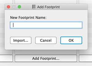
The screen to create a footprint.
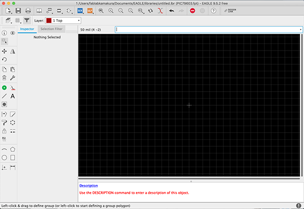
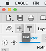
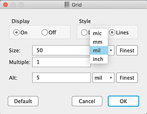
Since the dimensions are in inches, change the unit to mm to conform to the data sheet. You can change the unit from [Gred] menu.
Select [Smd] to connect the terminal and the contact. Select [Hole] for axial components.
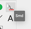
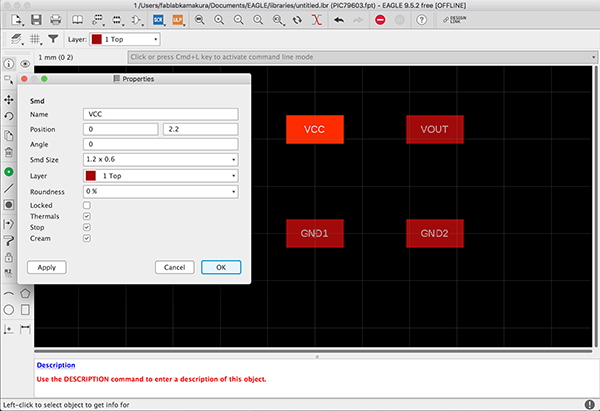
One of the [Smd] was set to the origin.
I calculated the positions of the other [Smd] from the origin by myself, referring to the recommended pattern diagram.
↓
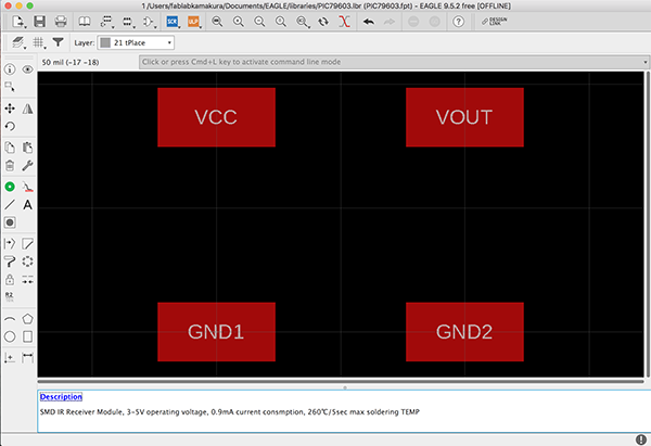
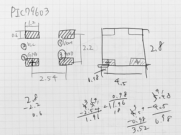
Assigned a function to each [Smd].
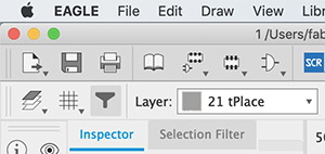
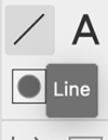
I need to set up a silk pattern to represent the position and information. Change [Layer] to tPlace and choose [Line] from the left menu.
Infine, aggiungere [>NOME] nello stesso modo della procedura dei simboli. Utilizzare [Text] per posizionarlo nella posizione migliore e cambiare [Layer] in tNames.
(5) Associare i nomi delle parti con impronte simboliche
Once you have completed this step, the final step is to associate the symbol with the footprint. In this step, we will link the symbol’s terminals to the contacts of the footprint and specify the comments and prefixes of the parts.
Select and open the device you created in step (1).
Place the symbol created in (2) from the [Add Part] button on the left.
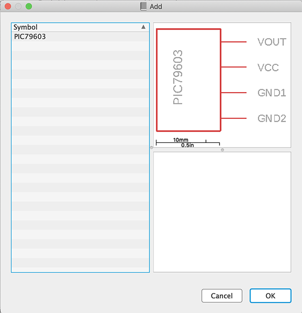
The Add window displays the symbols that were stored in the library. Specify them and press OK.
↓
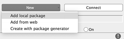
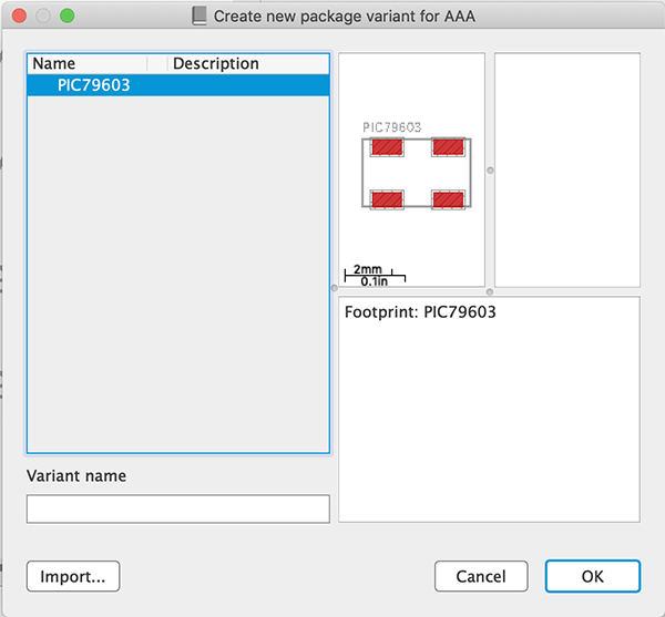
Next, specify the footprint. Select [New] on the right and then [Add local package].
The Add window shows the footprints stored in the library. Specify them and press OK.
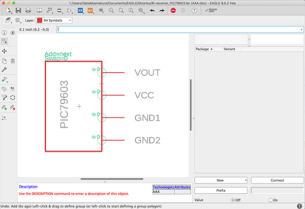
After placing the symbol and foot pattern, connect the terminals and contacts. Press the right [Connect] button.
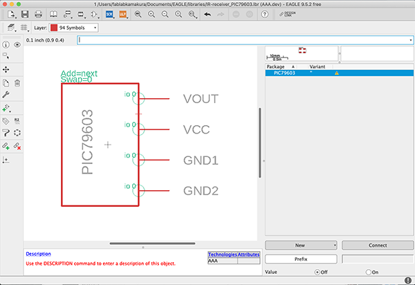
In the [Connect] window, the symbol’s terminal and footprint contacts are shown, select the function to be connected and press the [Connect] button in the lower left corner.
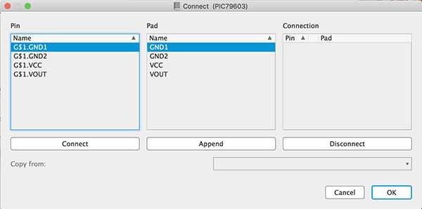
Match all the connectors together and it’s done. Now it will work as a homemade part.
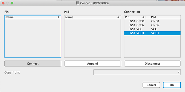
↓
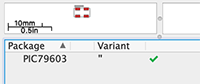
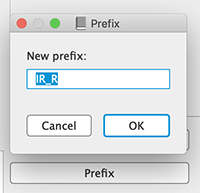
You can use it as it is, but you must specify the prefix of the parts at the end. Push the “Prefix” button at the bottom right. Since this part is an IR receiver, enter “IR_R” and press OK. Now every time you add a new part, it is automatically assigned a part number: IR_R1, IR_R2, IR_R3,,, etc.
Now you can use the symbol & footprint data of [Remote Control Receiver Module PIC79603] in EAGLE.
Consideration of board design
Before I created [Schematic] in EAGLE, I considered the design of the board to be produced.
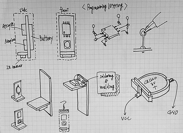
For this project, I came up with a mechanism to vertically connect two [substrate B], [substrate A] with [ATtiny85], [Neopixel], and [Battery] in place, and [substrate B] with [IR receiver] in place. So we decided to weld the two boards together during the soldering process. In order to design the boards as small as possible, we also decided to use tin-plated wire to fabricate pins for writing programs, and then drill holes in the boards and weld them together.
Creating a [Schematic]
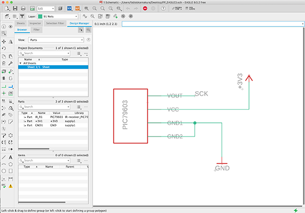
I was able to prepare the symbol and footprint data for the parts used on the earring side, so I created a schematic in EAGLE.
From the menu, [FIle] → [New] → [Schematic] to open the new data.
Click the [Add Part] button on the left to open the list of parts and place the parts you want to use.

I used the [Net] tool to wire up the placed components.

↓
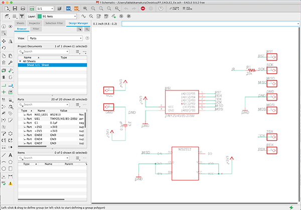
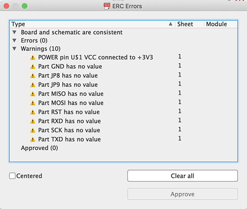
After wiring was completed, I used the [Electrical Rule Check] tool to check the wiring between components.
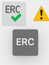
The warning [Part xxx has no value] is displayed, but I ignored it because it’s not necessary to make the board I’m going to create this time.
Lastly, I created a schematic for the infrared receiver side. Since this board is for welding, I will design it so that it will connect to the other board after I make the board diagram.
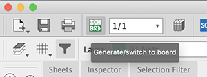
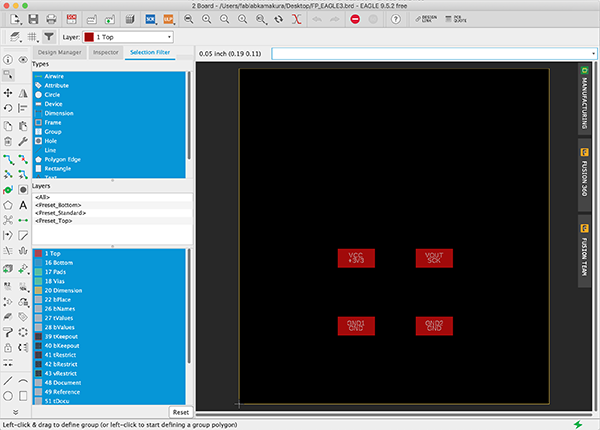
Creating the [Board]
Click the [Generate/switch to board] button at the top of the schematic window to move to the creation screen.
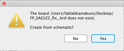
At first you will be asked if you want to generate it automatically from the schematic because there is no corresponding board diagram (.brd) file. Click the [Yes] button.
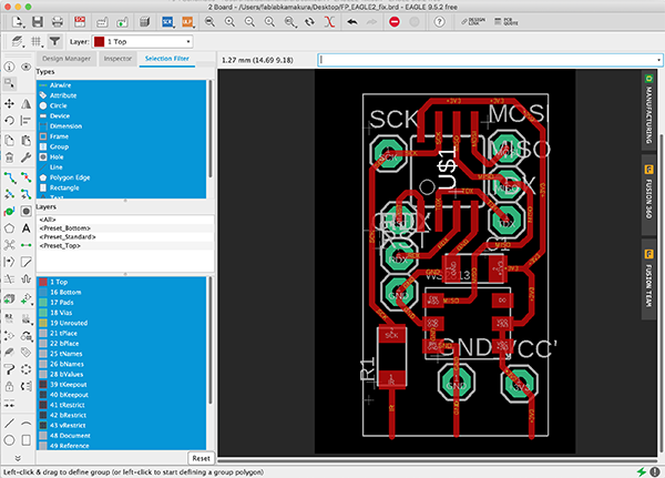
The board diagram was automatically generated, and I placed the components placed on the left side of the frame, keeping them close to the board structure I was considering.
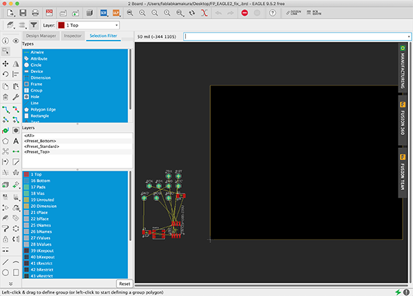
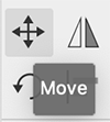
With the [Move] icon selected, we clicked on the part to be moved, moved it and then clicked again to place it. You can rotate the part by right-clicking while the part is selected.
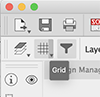
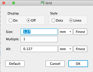
Set the unit of measurement in [mm] for moving the frame line by clicking the Grid button in the upper left corner.
After placing the components, use the [Route Airwire] to connect the components together.
Before that, I clicked the Grid button and changed the unit to inches to set the solid color. Then I set the width of the solid color to [0.016] and connected the wires.

The final board design for [Board A] looked like this.
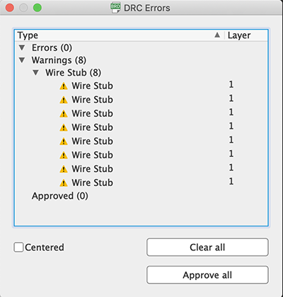
I used [DRC] to check that the board was designed in accordance with the design rules of board manufacturing, such as spacing between wires.
Click the [DRC] button at the bottom left of the Bode diagram window to display the DRC setting menu.
↓
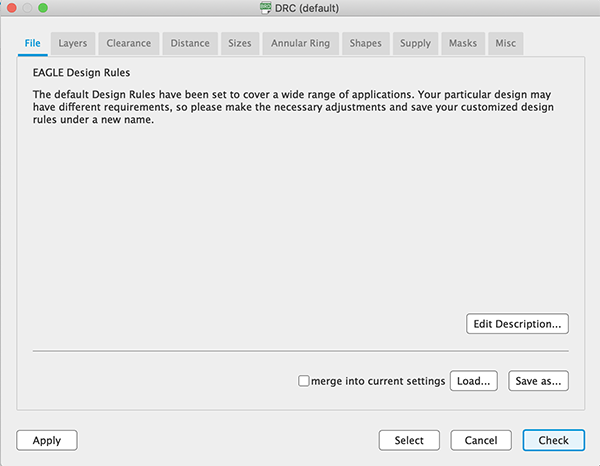
When I clicked the [Check] button, a window displaying the list of errors will appear. The warning “Wire Stub” is displayed, but I ignored it because it is not necessary to make the board that I will make this time.
That’s all we have to do for [Substrate B] in EAGLE. We create the pattern in accordance with the design of [Substrate A] created earlier using [Adobe Illustrator].
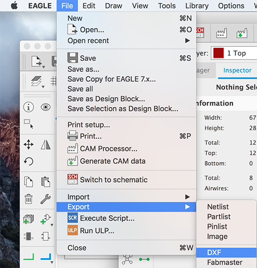
Exporting a Pattern Diagram
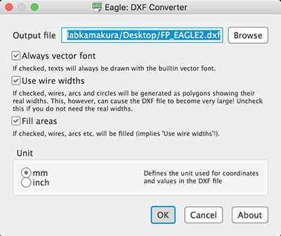
Export the created [Board A] and [Board B] designs as a [DXF] file in order to edit them in [Adobe Illustrator]. Make only [Top] and [Pads] of [Used Layers] visible when exporting. Note that if you make other layers visible, their data will be output as well.
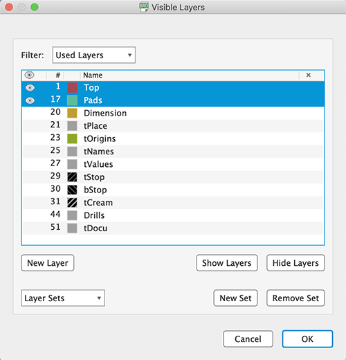
I selected [File]→[Export]→[DXF], made sure that the unit was set to [mm], and saved it on the desktop.
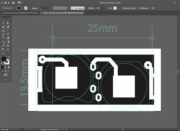
Corrections in [Adobe Illustrator]
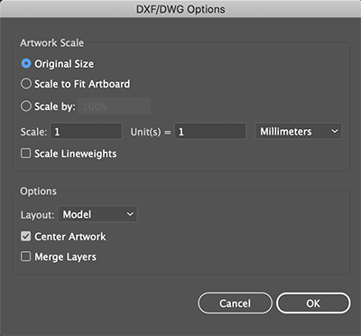
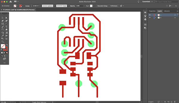
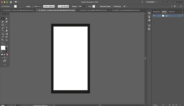
Open the [DXF] file of [Board A] exported by [File]→[Open] by [Original Size].
↓
The solids and pads were the color on the EAGLE.
↓
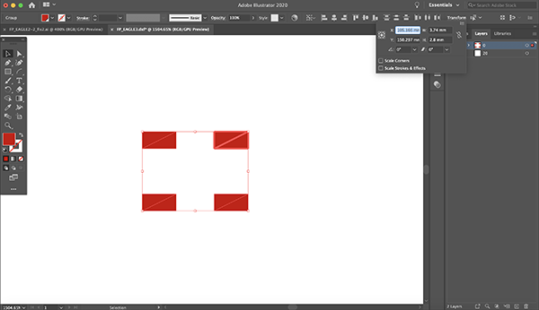
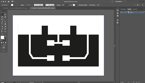
The solid and pad areas and other non-cutting areas were made in white and the rest of the area was made in black. The pads are drilled after the cutting process, but the size of the hole is too large for the end mill on the cutting machine, so I created marks for later machining. I also created a larger pad for the area to be welded to [substrate B].
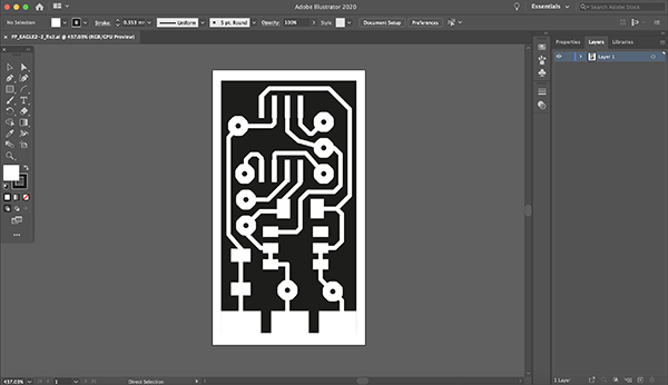
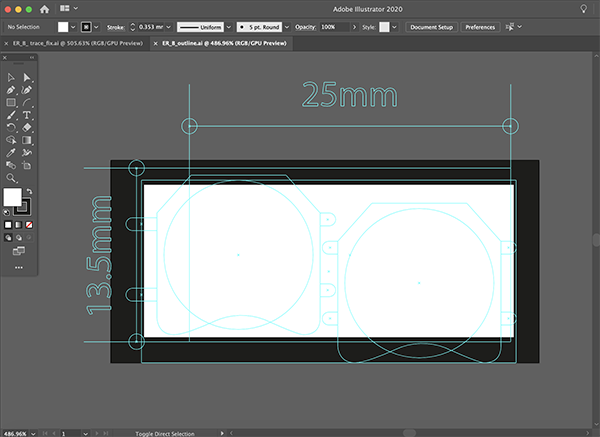
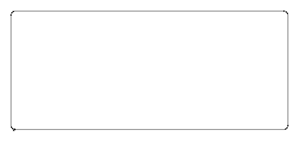
The outline data of the board was then created.
I finished making both the pattern and outline data and exported them in [PNG] format.
Similarly, I opened the [DXF] file of [Substrate B] in [Adobe Illustrator] and created a pattern drawing and outline data.
↓
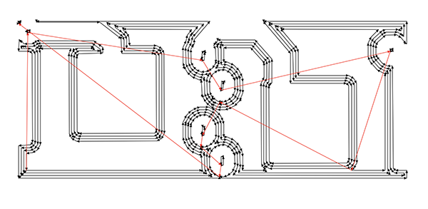
The center pad is connected to [GND] and the left and right pads are connected to [VCC].

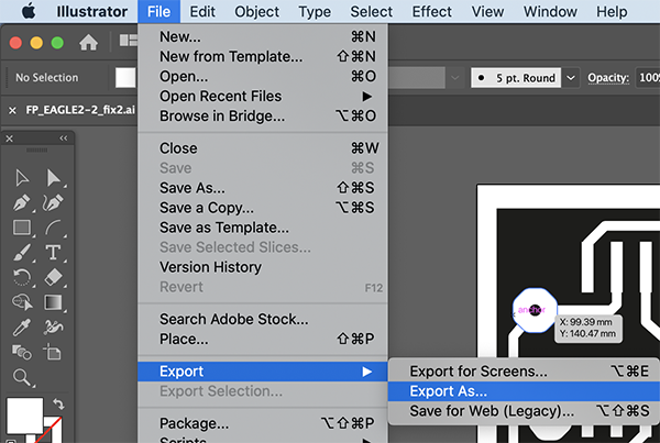
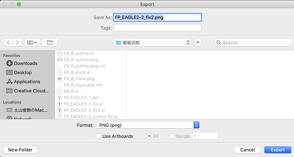
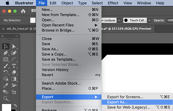
I exported the pattern and outline data as a [PNG] file. First, select [File]->[Export]->[Export As…] Select [File]->[Export]->[Export As…].
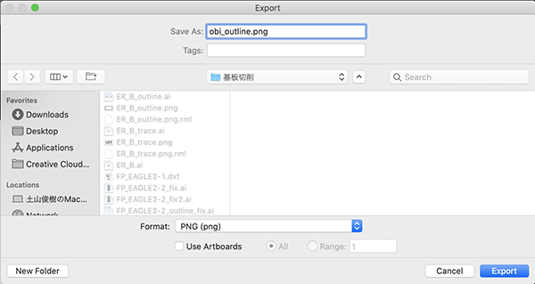
Choose [Format] to [PNG(png)] and click [Export].
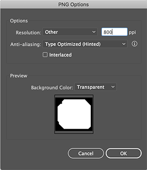
In the [PNG Option], set the resolution to [800dpi] and click [OK]. This is necessary to generate G-code in Mods.
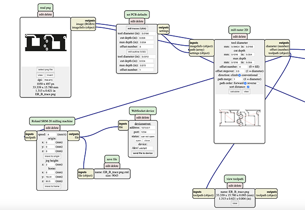
G code generation with Mods
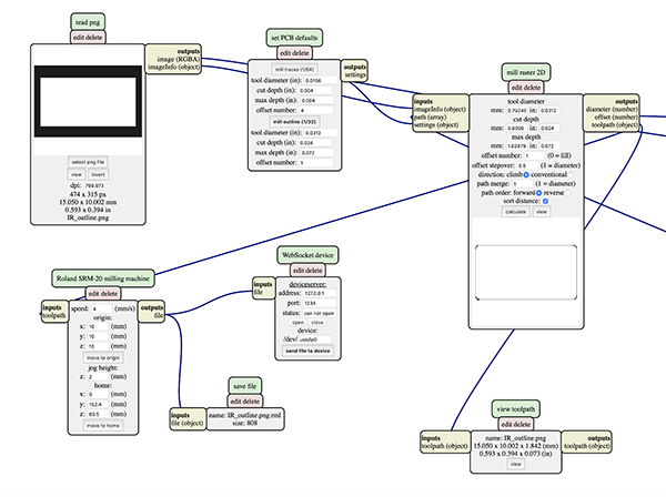
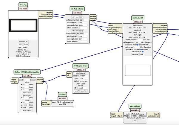
I used the pattern I created, a [PNG] file of outline data to generate the G code from the mods. Right click], [PROGRAMS], [OPEN SERVER PROGRAM], [ROLAND-mill-SRM_20-PCB png] to add the module. Another module was added by [right click], [MODULE], [OPEN SERVER MODULE], [SAVE FILE] to automatically save the file.
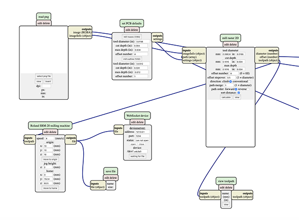
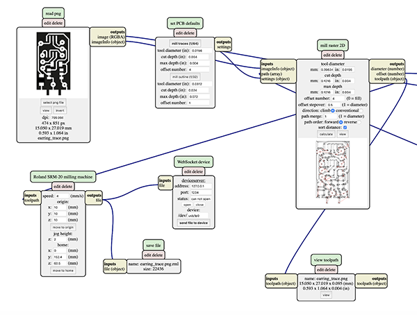
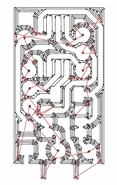
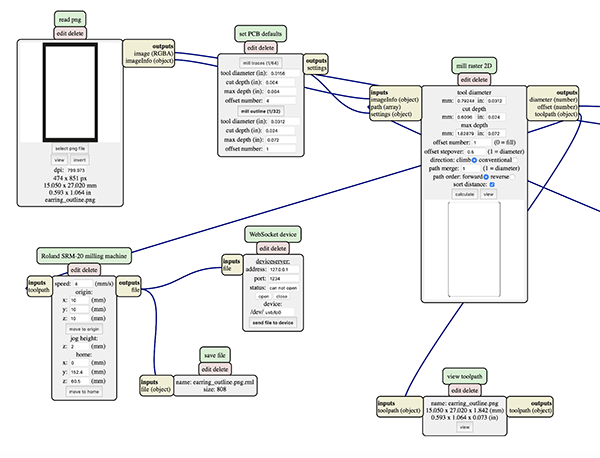
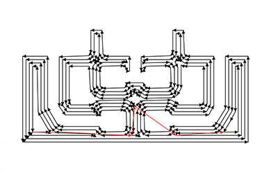
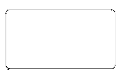
I selected the file to generate the G-code in [select png file] and clicked [calculate] in [mill raster 2D] to export the [rml] file. I clicked [view] and checked from the G-code preview screen to see if the end mill was running through the pattern.
earring pattern
earring outline

Infrared receiver pattern
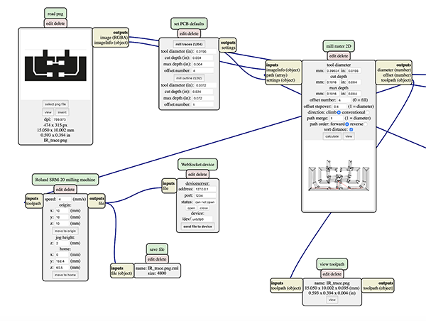
Infrared receiver outline
traces files・・・1/64
- In module Roland SRM-20 milling machine Origin
・x0(mm) - 0
・y0(mm) - 0
・z0(mm) - 0…These x0,y0,z0 are for setting up an offset from the origin save in
・z jog heighht - 2…This is the z distance that the mill will go up between the air travellings
・Speed - 4 or 3 mm/s for new end mills
- In module set PCB defaults
・tool diameter (in):0.0156
・cut depth (in): 0.004
・max depth (in): 0.004
・offset number:4
holes / outcut file・・・1/32
- Send the files to the machine
- In Mill Raster 2D module click in Calculate
・The file will be saved automatically into your download folder.
・x0(mm) - 0
・y0(mm) - 0
・z0(mm) - 0
・z jog heighht - 2…This is the z distance that the mill will go up between the air travellings
・Speed - 0.5
- In module set PCB defaults
・tool diameter (in):0.0312
・cut depth (in): 0.024
・max depth (in): 0.072
・offset number:4
I made sure the end mill was running firmly through the pattern.
Cutting with SRM-20
Then I used the SRM-20 to start cutting from the G-code I mentioned earlier.
Preparation for Processing
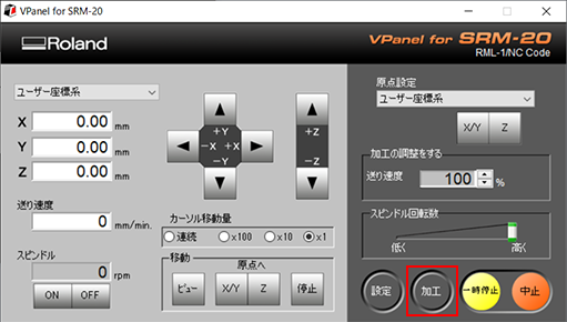
Cutting data of the circuit diagram is read by a VPanel.
Click [Processing] (red circle) in the VPanel to open the Advanced Settings.
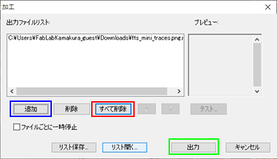
There is a possibility that there is a data file that someone processed last time, so click [Delete All] (red frame part).。
Data created earlier are read from [Add] (blue frame part) and click [Output] (green frame part).
↓
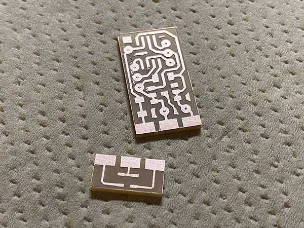
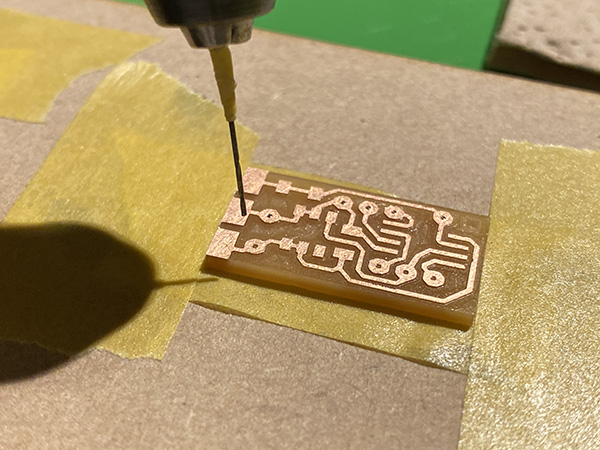
Substrate Cutting
Patern Cutting
I used a 1/64 bit end mill to cut the pattern on the board.
Outline Cutting
I used a 1/32 bit end mill to cut the outline of the board.
Unnecessary copper foil remains on the edge of the board after cutting, so it must be removed using an ultrasonic cutter.
Substrate Processing
I used a rutor to drill a hole in the cut board. The drill I used is [0.7mm].
I made sure that the tin-plated wire for the program write pins would go through.
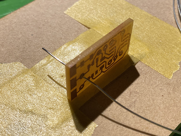
Processing of the pins
I used a pair of radio pliers to create the Q pins.
After soldering the Q pins, I cut off the part of the Q pins that protruded from the board.
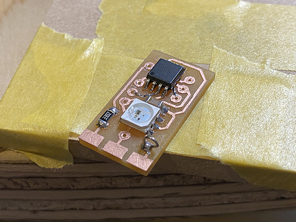
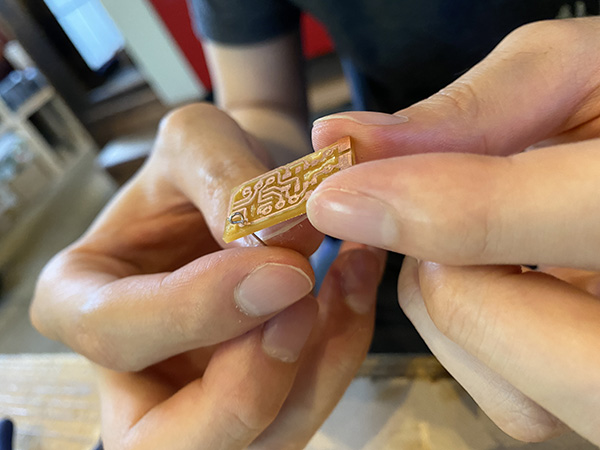
Soldering
I did the soldering.
The board of the infrared receiver was welded together using solder.
↓
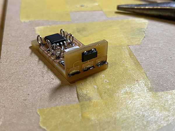
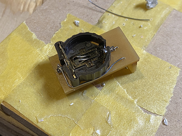
I used double sided tape to attach the battery box to the back side of the board. The hole in the center is for the GND and the left side is for the tin-plated wire that leads to the VCC.
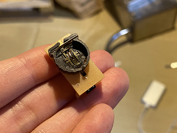
I was careful not to let the tin-plated wire stick out of the board when I soldered it.
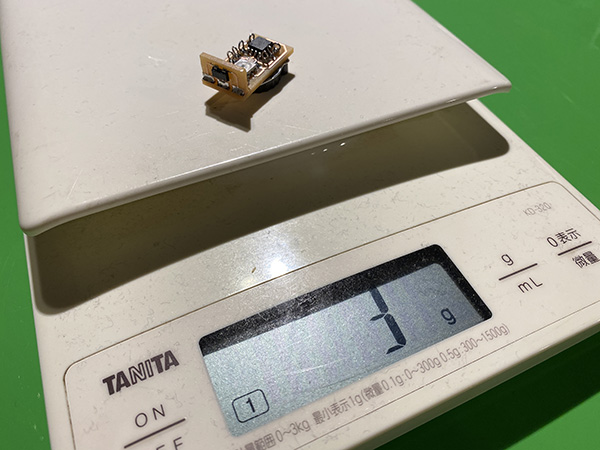
After all the soldering was done, I checked the weight and it was [3g] including the batteries.
Emdebbeging Programming (1)
I used multiple pins to write the program on the earring side. I used FabTiny as a writing machine.
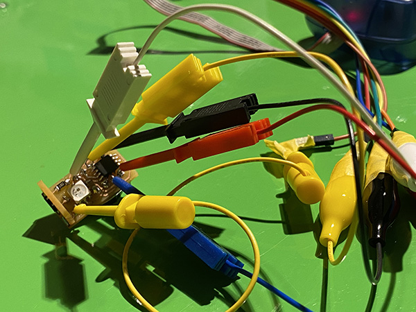
I wrote a program [Earring Neopixel Test2 (ino)] using an infrared remote control module for debugging.
I had built in a program to make the infrared remote control [0] light up, [1] red, [2] green, and [3] blue, but only the blue color of [3] didn’t light up. I found that the single button battery I used [Lithium battery CR1220 from Golden Power] was not enough voltage to display the blue color of the Neopixel. So I had to re-examine the button batteries. (Specified in [Re-examine the batteries])
Re-examine the batteries
I found that my original [Lithium battery CR1220 from Golden Power] did not have enough voltage to make the Neopixel glow blue.
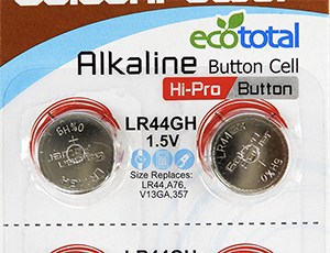
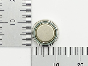
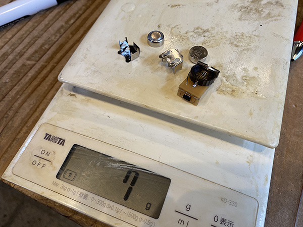
So I decided to review the button battery I use. This time I chose the [Alkaline Button Battery LR44 (Golden Power)]. The voltage per battery is 1.5V.
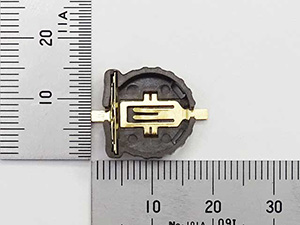
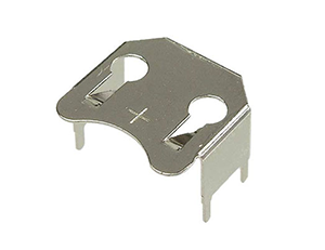
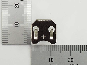
I chose [Battery board attachment holder (metal frame) for LR44] as the battery holder.
| component | vender | cost(JPY) | quanitity | total | notes |
|---|---|---|---|---|---|
| Alkaline Button Battery LR44 (Golden Power) | Akitsukidenshi | ¥100 | 1 | ¥100 | shop link |
| Battery board attachment holder (metal frame) for LR44 | Akitsukidenshi | ¥20 | 2 | ¥40 | shop link |
The combined weight of these parts and the board was [7g]. The target weight of [10g] or less will be achieved.
Creating a battery circuit
I came up with a battery circuit with new parts. This time I used [Adobe Illustrator] from the beginning instead of EAGLE to create the data. I aimed for a minimum size board based on the battery and battery holder.
Power Supply Board Trace
Power supply board outline
G code generation with Mods
I used the pattern I created, a [PNG] file of outline data to generate the G-code from the mods.
power supply pattern
Power supply circuit outline
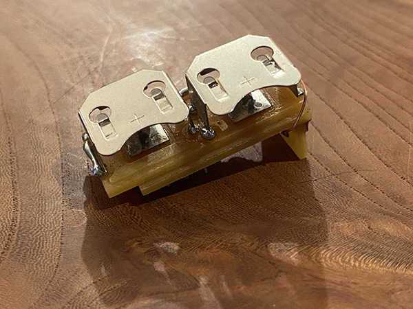
soldering
I used SRM-20 to cut and solder the board. I connected the battery circuitry to the VCC/GND pins on the ATtiny85 side with tin plated wires.
Emdebbeging Programming (2)
I wrote Earring Neopixel Test4 [ino] in the earring side. As a timeline, I’ve already written Controller Tapmode [ino] is already written in the board on the banding side.
I have confirmed that the program is working fine and the LEDs on the Neopixel are glowing fine.
5. Description of Important Weekly Learning Outcome
This time, the lab was disabled due to the coronavirus, so I have set up an environment to do the Fab Academy task at home.
First, I created a circuit using ATtiny44, but it didn’t work.
So I decided to put the motor on top of debugging.
Next, I used Arduinom to create circuits and programming.
The circuit we created this time is the circuit and programming needed to push out the materials of Extroder made by the final project.
From now on, the switch will be able to control the buttons that change the direction of the motor rotation.
6. Links to Files and Code
Footprint
- avr-7(ATtiny85 etc…) [lbr]
- IR receiver(PIC79603) [lbr]
- Neopixel(WS2813B) [lbr]
- eagle_fab(Resistor etc…) [lbr]
- fab(tact switch etc…) [lbr]
- adafruit(pin header etc…) [lbr]
EAGLE date
Final Project PNG file
- Earring trace date [png]
- Earring outline date [png]
- IR receiver trace date [png]
- IR receiver outline date [png]
- Battery circuit trace date [png]
- Battery circuit outline date [png]
![[png]](../../finalproject/files2/earring_trace.png)
![[png]](../../finalproject/files2/earring_outline.png)
![[png]](../../finalproject/files2/IR_trace.png)
![[png]](../../finalproject/files2/IR_outline.png)
![[png]](../../finalproject/files3/battery_circuit_trace.png)
![[png]](../../finalproject/files3/battery_circuit_outline.png)
Final Project RML file
- Earring trace date [rml]
- Earring outline date [rml]
- IR receiver trace date [rml]
- IR receiver outline date [rml]
- Battery circuit trace date [rml]
- Battery circuit outline date [rml]
![[rml]](../../finalproject/files3/earring_trace.png.rml)
![[rml]](../../finalproject/files3/earring_outline.png.rml)
![[rml]](../../finalproject/files3/IR_trace.png.rml)
![[rml]](../../finalproject/files3/IR_outline.png.rml)
![[rml]](../../finalproject/files3/battery_circuit_trace.png.rml)
![[rml]](../../finalproject/files3/battery_circuit_outline.png.rml)