Mechanical design / Machine design
1. Weekly Brief Summary
This time, students from FabLab Kamakura and FabLab Kannai decided to create an assignment.
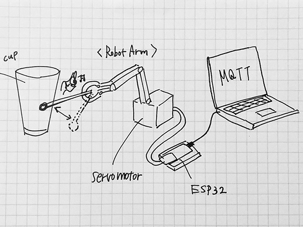
We decided to develop our own musical instrument machines and use them to perform an orchestra online.
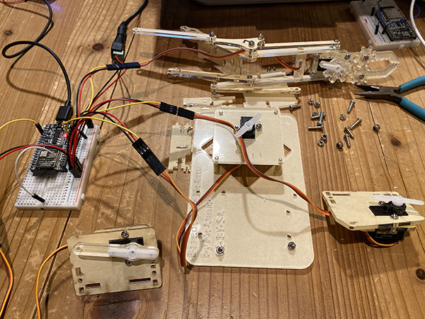
The performance environment was built with [zoom], [ESP32] was used to control each machine, and [MQTT] was used to control the ensemble.
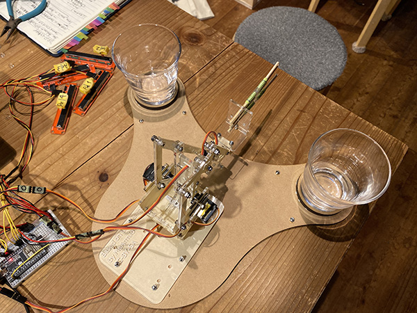
I made a percussion machine using a robot arm and participated in the performance.
2. Weekly Assignment Requirement
Mechanical Design (part 1 of 2)
Group assignment
- Design a machine that includes (mechanism + actuation + automation)
- Build the mechanical parts and operate it manually.
- Document the group project
Individual assignment
- Document your individual contribution.
Machine Design (part 2 of 2)
Group assignment
- Actuate and automate your machine.
- Document the group project
Individual assignment
- Document your individual contribution.
Learning outcomes
- Work and communicate effectively in a team and independently
- Design, plan and build a system
- Analyse and solve technical problems
- Recognise opportunities for improvements in the design
Have you?
- Explained your individual contribution to this project on your own website
On the group page, has your group
- Shown how your team planned and executed the project
- Described problems and how the team solved them
- Listed future development opportunities for this project
- Included your design files
- Optionally included an aprox. 1 min video (1920x1080 HTML5 MP4) + slide (1920x1080 PNG)
3. Group Assignment Link
Kamakura Group Assignment Week17
4. Description of Assignment Work
MTM Planning
I decided to make a percussion instrument using the robot arm mechanism.
This is the idea sketch.
Robot Arm Production
I downloaded the [DXF] data of a robot arm using a servo motor from Thingiverse.
Download
When I checked the data, there were some defects in the design, such as the hole size, so I fixed it in [Adobe Illustrator].
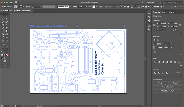
I converted the data to PDF and output it from CorelDraw to a laser cutter.
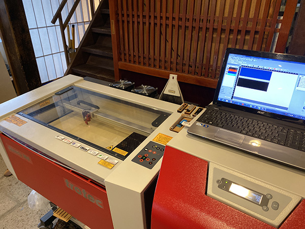
| Machine | Material | Power | Speed | Hz |
|---|---|---|---|---|
| trotec speedy 100 | acrylic 3mm | 90 | 0.5 | 20000 |
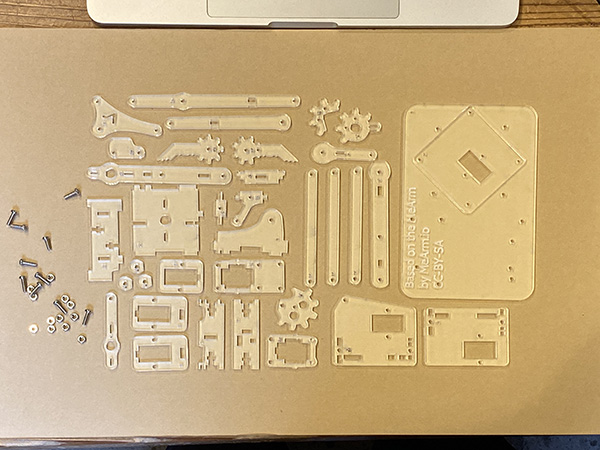
Robot Arm Assembly Video
After cutting out the materials, I assembled the robot by referring to the video on youtube.
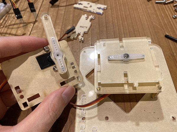
Set 0 Position of Servo Motor
Set the Initial Position of the Servo Motor
In fact, I worked on this process after pumping the robot arm.
However, if you assemble without setting the initial position of the servo motor, problems will occur when you move it.
So, this time, I decided to set the initial position of the servo motor to 90 degrees and assemble the parts in a fixed state.
Programminng
#include <ESP32Servo.h>

Servo servo1; // create four servo objects
Servo servo2;
Servo servo3;
Servo servo4;
int servo1Pin = 12;
int servo2Pin = 13;
int servo3Pin = 14;
int servo4Pin = 15;

// Published values for SG90 servos; adjust if needed
int minUs = 500;
int maxUs = 2400;

void setup() {
  servo1.setPeriodHertz(50);      // Standard 50hz servo
  servo1.attach(servo1Pin, minUs, maxUs);
  servo2.setPeriodHertz(50);      // Standard 50hz servo
  servo2.attach(servo2Pin, minUs, maxUs);
  servo3.setPeriodHertz(50);      // Standard 50hz servo
  servo3.attach(servo3Pin, minUs, maxUs);
  servo4.setPeriodHertz(50);      // Standard 50hz servo
  servo4.attach(servo4Pin, minUs, maxUs);

  servo1.write(90);
  servo2.write(90);
  servo3.write(90);
  servo4.write(90);
}

void loop(){
}
Robot Arm Assembly
I did the assembly work while referring to the “Robot arm assembly video”.
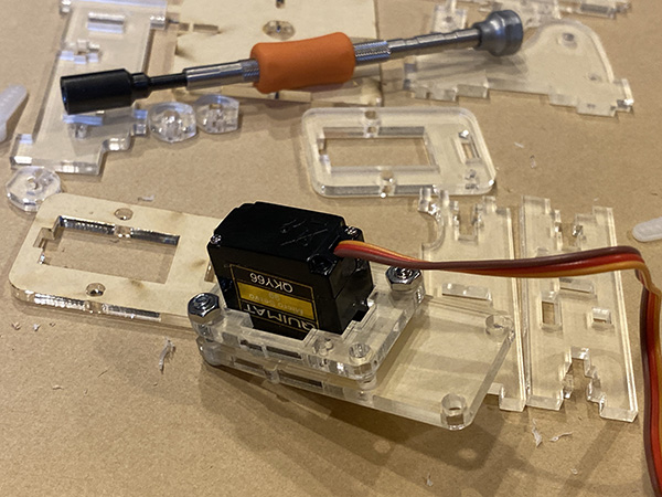
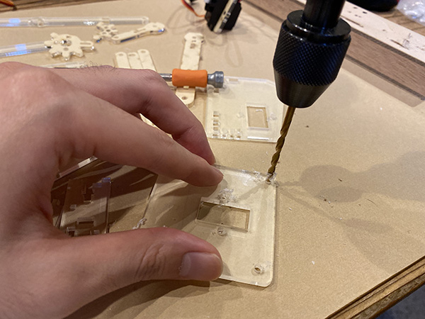
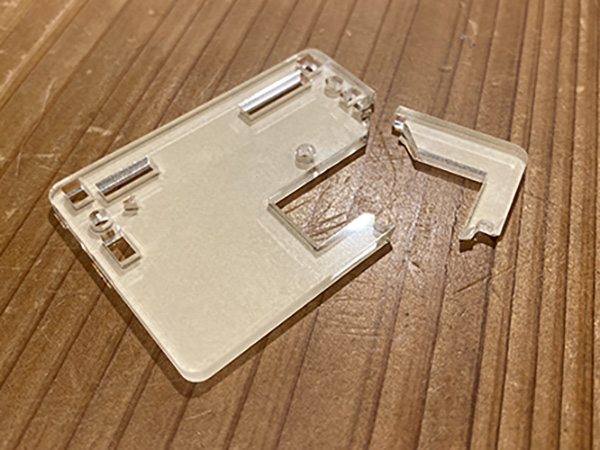
While assembling, there were some places where the size of the screw holes didn’t fit, so I made a hole by hand using a drill.
At that time the parts broke and I needed to recut them with a laser cutter.
↓
At that time the parts broke and I needed to recut them with a laser cutter.
It is safer to work slowly and carefully when using the drill.
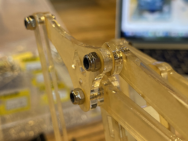
In addition, I noticed a serious mistake when it was assembled to some extent.
Where I used a nylon nut for the drive, I was using a hex nut.
If it is a hexagon nut, it will come off when the arm moves several times.
I reattached the part that used all hex nuts.
- Hexagon Nut・・・×
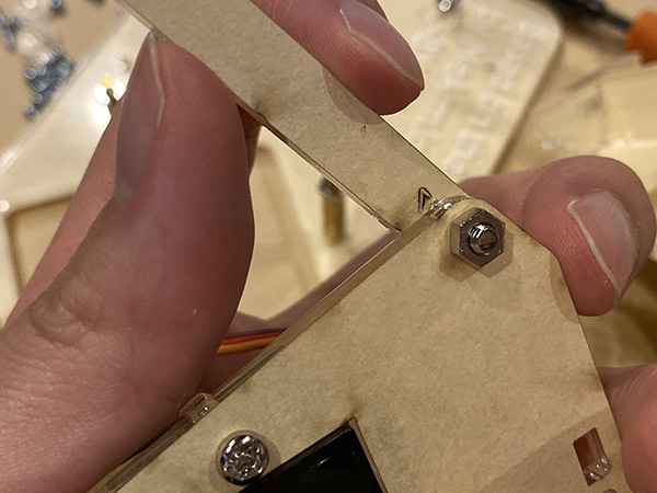
- Nylon Nut・・・○
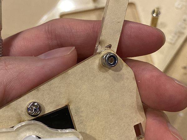
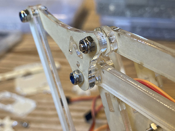
But I also failed with nylon nuts.
For nylon nuts, it is necessary to allow the screw to protrude from the tip of the nut by about 1 to 2 mm.
So I replaced all the screws used for the nylon nuts with a slightly larger size.
- Screw that does not protrude from the nylon nut・・・×
- A screw that slightly protrudes from the nylon nut・・・○
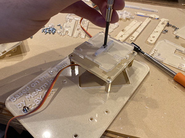
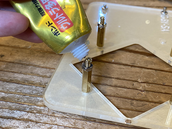
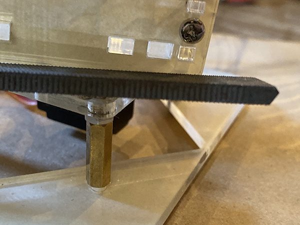
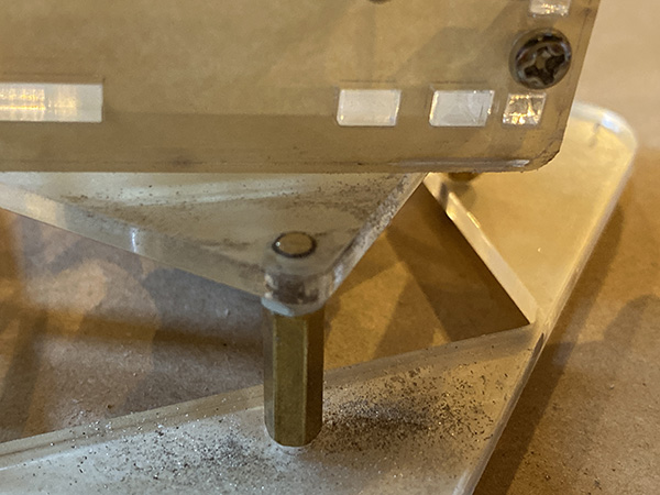
Finally, I fixed the pedestal part and the robot arm with a strong adhesive.
The reason is that there was no suitable screw.
After fixing, when the arm rotated, the bottom of the body and the head of the protruding screw were caught.
So I used a metal file to cut off the protruding part.
↓
↓
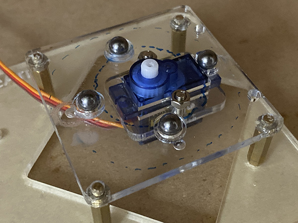
Further, when the arm is rotated in the direction, the center of gravity is tilted in the forward direction, which slows down the movement.
It was stable when I held the back with my finger, but I needed a load of about 400g.
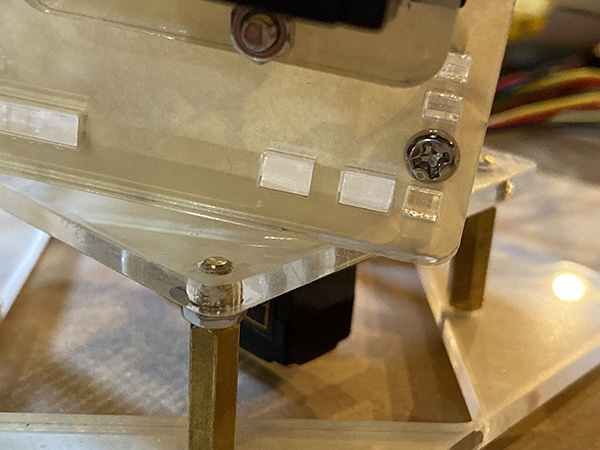
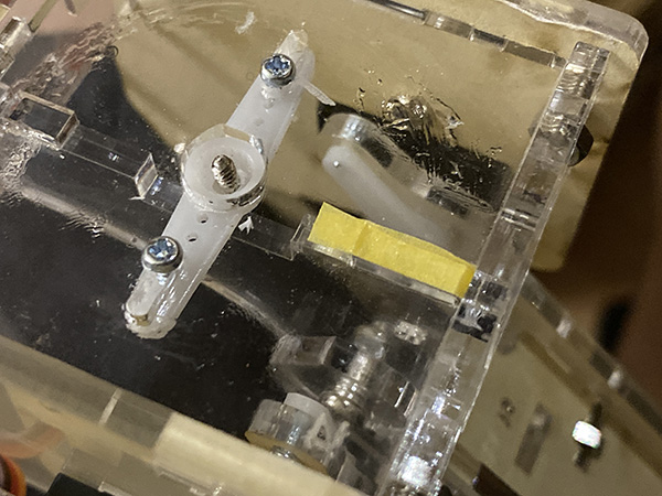
So I decided to put a ball bearing between the base and the robot arm. Acrylic cut parts are attached to fix the ball bearings.
This stabilizes the rotating robot arm.

↓
In addition, the groove formed when the parts were combined on the back side of the body part of the robot arm was caught during rotation, causing the movement to slow down.
So I hurriedly adjusted the masking tape to the size of the groove to reduce the friction caused by the steps.
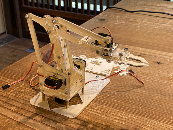
Assembled Robot Arm
Programming of Robot Arm
I used ESP32 for the microcomputer that controls the robot arm.
We will use MQTT for the final ensemble of lab students.
So I had to use ESP32 to control the robot arm.
I first set up the ESP32 development environment.
[ESP-WROOM-32] is used this time.
Construction of Development Environment for ESP-WROOM-32
Used Tools
- MacBook Pro(macOS Catalina 10.15.4)
- micro USB-B Cable
Download
- Serial Driver Download
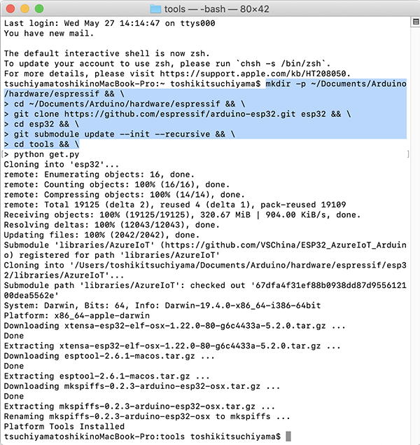
(1) Enter the Following Command from the Terminal
※If the Arduino IDE is already downloaded on your PC
mkdir -p ~/Documents/Arduino/hardware/espressif && \
cd ~/Documents/Arduino/hardware/espressif && \
git clone https://github.com/espressif/arduino-esp32.git esp32 && \
cd esp32 && \
git submodule update --init --recursive && \
cd tools && \
python get.py
↓
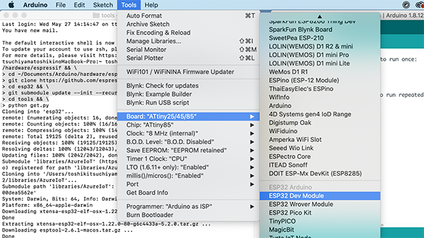
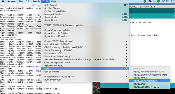
I started the Arduino IDE and confirmed that there is [Tools]→[Board]→[ESP32 DevModule].
(2) Install Serial Driver

↓
I restarted the Arduino IDE and confirmed that [Tools]→[Serial Port]→[/dev/cu.SLAB_USBtoUART].
(3) Operation Check
I used the LEDs to confirm that the ESP32 works fine.
void setup() {// the setup function runs once when you press reset or power the board
  pinMode(2, OUTPUT);  // initialize digital pin LED_BUILTIN as an output.
}

void loop() {// the loop function runs over and over again forever
  digitalWrite(2, HIGH);   // turn the LED on (HIGH is the voltage level)
  delay(1000);                       // wait for a second
  digitalWrite(2, LOW);    // turn the LED off by making the voltage LOW
  delay(1000);                       // wait for a second
}
Control Servo Motor with ESP32
The robot arm manufactured this time controls and moves four servo motors.
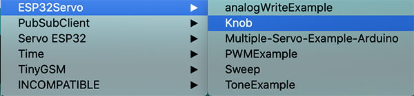
I downloaded the library [ESP32Servo.h] to control the servo motor with ESP32.
(1) Move One Servo Motor
I used the sample program that rotates the shaft of the servo motor from 0 to 180 degrees from site (JPN).
For [int servo1Pin], input the output pin used this time.
I used a breadboard to wire as shown in the picture.
回路図
Programming
#include <ESP32Servo.h>

Servo servo1; // create four servo objects
int servo1Pin = 2;

// Published values for SG90 servos; adjust if needed
int minUs = 500;
int maxUs = 2400;

int pos = 0;      // position in degrees

void setup() {
  servo1.setPeriodHertz(50);      // Standard 50hz servo
  servo1.attach(servo1Pin, minUs, maxUs);
}

void loop() {
  for (pos = 0; pos <= 180; pos += 1) { // sweep from 0 degrees to 180 degrees
    // in steps of 1 degree
    servo1.write(pos);
    delay(4);             // waits 20ms for the servo to reach the position
  }
  for (pos = 180; pos >= 0; pos -= 1) { // sweep from 180 degrees to 0 degrees
    servo1.write(pos);
    delay(4);
  }
}
| Function | Syntax | Parameter |
|---|---|---|
| attach(pin) Assign servo variables to pins. |
servo.attach(pin) servo.attach(pin, min, max) |
servo: Servo type variable pin: Pin number to which the servo is assigned min (Option): Pulse width (microseconds) when the servo angle is 0 degrees. Default is 544 max(Option): Pulse width (microseconds) when the servo angle is 180 degrees. Default is 2400 |
The servo motor worked, but it didn’t seem to rotate 180 degrees like the code, so I changed some of the code.
- nt minUs = Change 500 to 100 → nothing changes
- ny maxUs = Change to 1000 → Motor rotation range has decreased
- nnt maxUS = Change to 3000 → same as the beginning (maximum value 2400?)
- Change delay(2) in void loop to both (500) → It became very slow
- Changed delay(500) in void loop to both (10) → Motion is slower than that in (2), but it seems to be moving properly in the range of 0 to 180 degrees.
- Change delay (10) in void loop to both (5) → It seems that it works properly in the range of 0 to 180 degrees. Is the movement momentarily faster when the motor reverses?
- Change delay(5) in void loop to both (1) → The movement became faster, but the operating range became extremely narrow.
- Changed delay(3) in void loop to both (3) → faster movement, but wider range of operation. Is it open from 0 to 180 degrees?
- Change delay(4) in void loop to both (4) → The movement is slow, but the motor is open from 0 to 180 degrees.
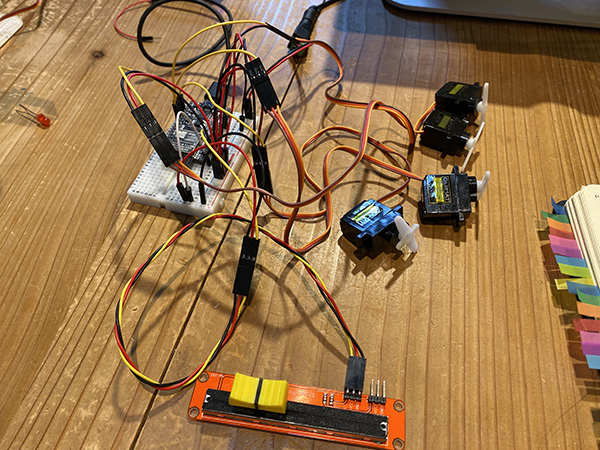
(2) Move One Servo Using a Slide Potentiometer
I used the downloaded ESP32Servo sample code to control the servo position using a potentiometer (variable resistor).
 回路図
回路図
Programming
#include <ESP32Servo.h>

Servo myservo;  // create servo object to control a servo

// Possible PWM GPIO pins on the ESP32: 0(used by on-board button),2,4,5(used by on-board LED),12-19,21-23,25-27,32-33
int servoPin = 2;      // GPIO pin used to connect the servo control (digital out)
// Possible ADC pins on the ESP32: 0,2,4,12-15,32-39; 34-39 are recommended for analog input
int potPin = 34;        // GPIO pin used to connect the potentiometer (analog in)
int ADC_Max = 4096;     // This is the default ADC max value on the ESP32 (12 bit ADC width);
// this width can be set (in low-level oode) from 9-12 bits, for a
// a range of max values of 512-4096

int val;    // variable to read the value from the analog pin

void setup()
{
  myservo.setPeriodHertz(50);// Standard 50hz servo
  myservo.attach(servoPin, 500, 2400);   // attaches the servo on pin 18 to the servo object
// using SG90 servo min/max of 500us and 2400us
// for MG995 large servo, use 1000us and 2000us,
// which are the defaults, so this line could be
// "myservo.attach(servoPin);"
}

void loop() {
  val = analogRead(potPin);            // read the value of the potentiometer (value between 0 and 1023)
  val = map(val, 0, ADC_Max, 0, 180);     // scale it to use it with the servo (value between 0 and 180)
  myservo.write(val);                  // set the servo position according to the scaled value
  delay(50);                          // wait for the servo to get there
}
GPIO PIN・・・Also called a general-purpose I/O port.
As the name implies, it is a port that can input and output.
Specifically, the following can be done.
It becomes an indispensable pin when handling sensors and motors.
- Receive signal from sensor (input)
- Receive switch ON/OFF signal (input)
- Send a signal to turn on the LED (output)
- Send a signal to move the motor (output)
Read Datasheet

· ESP32 capable ADC pins: 0, 2, 4, 12-15, 32-39
→ I used 12 to 15 for the servo motor.

・34 to 39 recommended for analog input
→The potentiometer used was from 32 to 35.
- int servoPin = 18 → changed to 2 → works without problems. However, I am worried about the jerks. I felt that there was a time lag between the potentiometer and the servo motor.
- Change delay (200) in void loop to (100) → It may be just a problem with the operation, but I felt that the time lag might have disappeared.
- Change delay(100) in void loop to (50) → I feel that it works smoothly. Does it make a difference if you move it in detail? → The smaller the delay() number is, the more it works as if the meter was moved. When I moved finely at delay (200), the rotation of the motor could not keep up with the speed to move the meter.
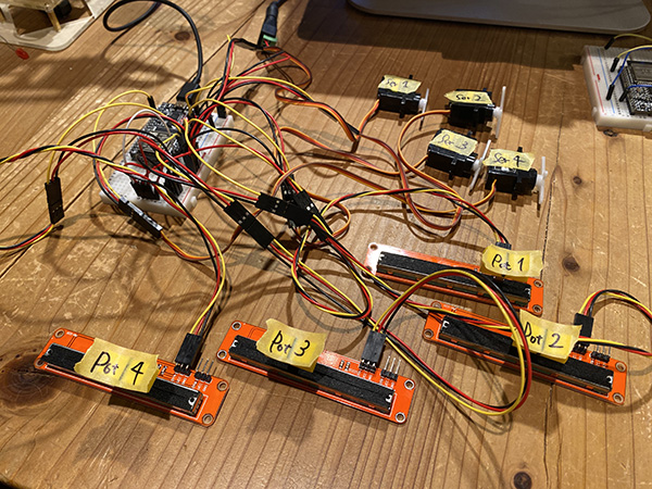
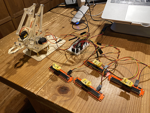
(3) Move 4 Servos Using Slide Potentiometer
I modified the above program and created the code to control four servomotors using one potentiometer.
 回路図
回路図
Programming
#include <ESP32Servo.h>

Servo myservo1;  // create servo object to control a servo
Servo myservo2;
Servo myservo3;
Servo myservo4;

// Possible PWM GPIO pins on the ESP32: 0(used by on-board button),2,4,5(used by on-board LED),12-19,21-23,25-27,32-33
int servoPin1 = 12;// GPIO pin used to connect the servo control (digital out)
int servoPin2 = 13;
int servoPin3 = 14;
int servoPin4 = 15;
// Possible ADC pins on the ESP32: 0,2,4,12-15,32-39; 34-39 are recommended for analog input
int potPin = 34;        // GPIO pin used to connect the potentiometer (analog in)
int ADC_Max = 4096;     // This is the default ADC max value on the ESP32 (12 bit ADC width);
// this width can be set (in low-level oode) from 9-12 bits, for a
// a range of max values of 512-4096

int val;    // variable to read the value from the analog pin

void setup()
{
  myservo1.setPeriodHertz(50);// Standard 50hz servo
  myservo2.setPeriodHertz(50);
  myservo3.setPeriodHertz(50);
  myservo4.setPeriodHertz(50);
  myservo1.attach(servoPin1, 500, 2400);  // attaches the servo on pin 18 to the servo object
  myservo2.attach(servoPin2, 500, 2400);  // using SG90 servo min/max of 500us and 2400us
  myservo3.attach(servoPin3, 500, 2400);  // for MG995 large servo, use 1000us and 2000us,
  myservo4.attach(servoPin4, 500, 2400);  // which are the defaults, so this line could be
  // "myservo.attach(servoPin);"
}

void loop() {
  val = analogRead(potPin);            // read the value of the potentiometer (value between 0 and 1023)
  val = map(val, 0, ADC_Max, 0, 180);     // scale it to use it with the servo (value between 0 and 180)
  myservo1.write(val); // set the servo position according to the scaled value
  myservo2.write(val);
  myservo3.write(val);
  myservo4.write(val);
  delay(50);                          // wait for the servo to get there
}
【ADC pin (analog input) not usable for servo but usable for potentiometer】
A0ー36 / A3ー39 / A4ー32 / A5ー33 / A6ー34 / A7ー35 / A10ー4 / A11ー0 / A12ー2 / A13ー15 / A14ー13 / A15ー12 / A16ー14 / A17ー27 / A18ー25 / A19ー26
When I wrote the program, it only moved up to two servos.
There is a possibility that the servo motor did not work because the control voltage was insufficient.
One of the servomotors didn’t insert the jumper wire so I reconnected it and it worked.
But the other one didn’t move at all. So I used an oscilloscope for debugging.
- Servo motor waveform that is operating normally
- Servo motor waveform not moving
As a result of debugging, I found that one of the servo motors was defective.
So I replaced the defective servo motor with a new one.
When I read the program again, all the servo motors worked normally.
(4) Move One Potentiometer per Servo Motor
I created a program to control the motor by connecting a potentiometer to pins 32, 33, 34 and 35.
Programming
#include <ESP32Servo.h>

Servo myservo1;  // create servo object to control a servo
Servo myservo2;
Servo myservo3;
Servo myservo4;

// Possible PWM GPIO pins on the ESP32: 0(used by on-board button),2,4,5(used by on-board LED),12-19,21-23,25-27,32-33
int servoPin1 = 12;// GPIO pin used to connect the servo control (digital out)
int servoPin2 = 13;
int servoPin3 = 14;
int servoPin4 = 15;
// Possible ADC pins on the ESP32: 0,2,4,12-15,32-39; 34-39 are recommended for analog input
int potPin1 = 32;        // GPIO pin used to connect the potentiometer (analog in)
int potPin2 = 33;
int potPin3 = 34;
int potPin4 = 35;
int ADC_Max = 4096;     // This is the default ADC max value on the ESP32 (12 bit ADC width);
// this width can be set (in low-level oode) from 9-12 bits, for a
// a range of max values of 512-4096

int val;    // variable to read the value from the analog pin

void setup(){
  myservo1.setPeriodHertz(50);// Standard 50hz servo
  myservo2.setPeriodHertz(50);
  myservo3.setPeriodHertz(50);
  myservo4.setPeriodHertz(50);
  myservo1.attach(servoPin1, 500, 2400);  // attaches the servo on pin 18 to the servo object
  myservo2.attach(servoPin2, 500, 2400);  // using SG90 servo min/max of 500us and 2400us
  myservo3.attach(servoPin3, 500, 2400);  // for MG995 large servo, use 1000us and 2000us,
  myservo4.attach(servoPin4, 500, 2400);  // which are the defaults, so this line could be
// "myservo.attach(servoPin);"
}

void loop() {
  val = analogRead(potPin1);            // read the value of the potentiometer (value between 0 and 1023)
  val = map(val, 0, ADC_Max, 0, 180);     // scale it to use it with the servo (value between 0 and 180)
  myservo1.write(val); // set the servo position according to the scaled value

  val = analogRead(potPin2);
  val = map(val, 0, ADC_Max, 0, 180);
  myservo2.write(val);

  val = analogRead(potPin3);
  val = map(val, 0, ADC_Max, 0, 180);
  myservo3.write(val);

  val = analogRead(potPin4);
  val = map(val, 0, ADC_Max, 0, 180);
  myservo4.write(val);

  delay(50);                        // wait for the servo to get there
}
Create a Servo Motion Function for Playing
I connected the control program using the created potentiometer to the servo motor of the robot arm.
I checked how the servo motor of the robot arm works and at what angle.
① Creating a Program to Shake Your Head from Side to Side
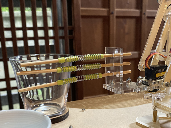
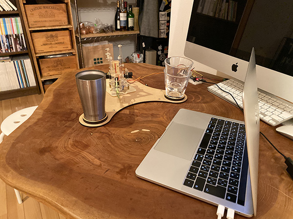
This time, I put a glass cup on the part attached to the tip of the robot arm and make a sound. Also, the timing of moving the robot arm must be controlled rhythmically.
I created data using Adobe Illustrator for the “sound producing parts” to be attached to the center of the robot arm, and made it using a laser cutter.
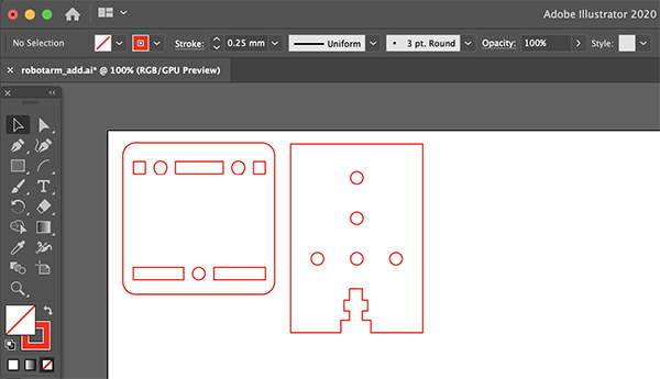
Next, I wrote a program to rotate the robot arm left and right with the same rhythm.
This is a program in which the robot arm makes repeated round trips in the range of 10 to 170 degrees. Based on this program, create a program that hits the cup rhythmically.
Programming
#include <ESP32Servo.h>

Servo servo1;// create four servo objects
int servo1Pin = 12;

// Published values for SG90 servos; adjust if needed
int minUs = 500;
int maxUs = 2400;

int pos = 0;      // position in degrees

void setup() {
  servo1.setPeriodHertz(50);      // Standard 50hz servo
  servo1.attach(servo1Pin, minUs, maxUs);
}

void loop() {
  for (pos = 10; pos <= 170; pos += 1) { // sweep from 0 degrees to 180 degrees
    // in steps of 1 degree
    servo1.write(pos);
    delay(2);             // waits 20ms for the servo to reach the position
  }
  for (pos = 170; pos >= 10; pos -= 1) { // sweep from 180 degrees to 0 degrees
    servo1.write(pos);
    delay(2);
  }
}
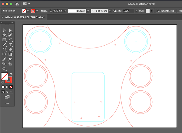
I made a base with a laser cutter and fixed it so that the robot arm and the struck cup did not move.
The data was created with Adobe Illustator.
I received advice from the instructor as “improvement plans”, “making rhythm” and “making metal parts that hit the cup”.
I created a new program with the goal of “creating a rhythm”.
[int servo1Pin = 12;] is a servo motor that rotates the robot arm left and right.
[int servo2Pin = 13;] and [int servo3Pin = 14;] are programmed to fix the position of the tip part of the robot arm.
Programming
#include <ESP32Servo.h>

Servo servo1;// create four servo objects
Servo servo2;
Servo servo3;
int servo1Pin = 12;
int servo2Pin = 13;
int servo3Pin = 14;

// Published values for SG90 servos; adjust if needed
int minUs = 500;
int maxUs = 2400;

int pos = 0;      // position in degrees

void setup() {
  servo1.setPeriodHertz(50);      // Standard 50hz servo
  servo1.attach(servo1Pin, minUs, maxUs);

  servo2.write(45);
  servo3.write(90);
}

void loop() {
  for (pos = 10; pos <= 90; pos += 1) { // sweep from 0 degrees to 180 degrees
    // in steps of 1 degree
    servo1.write(pos);
    delay(1);             // waits 20ms for the servo to reach the position
  }
  for (pos = 90; pos >= 10; pos -= 1) { // sweep from 180 degrees to 0 degrees
    servo1.write(pos);
    delay(1);
  }
  delay(1);
  for (pos = 10; pos <= 90; pos += 1) { // sweep from 0 degrees to 180 degrees
    // in steps of 1 degree
    servo1.write(pos);
    delay(1);             // waits 20ms for the servo to reach the position
  }
  for (pos = 90; pos >= 10; pos -= 1) { // sweep from 180 degrees to 0 degrees
    servo1.write(pos);
    delay(1);
  }

   for (pos = 10; pos <= 170; pos += 1) { // sweep from 0 degrees to 180 degrees
    // in steps of 1 degree
    servo1.write(pos);
    delay(2);             // waits 20ms for the servo to reach the position
  }
  servo1.write(90);
  delay(500);
}
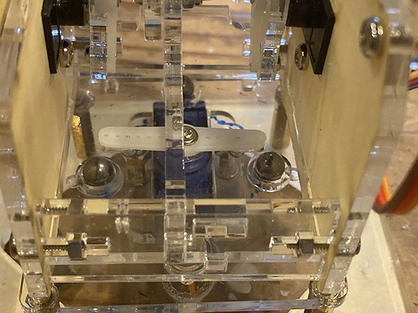
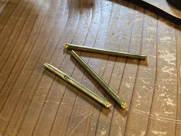
The remedy of “metalizing the parts that hit the cup” was solved using a brass rod with a diameter of 3 mm. This makes the volume louder than in previous versions.
MQTT Connection
Finally, I connected the robot arm I made to MQTT and prepared for joining the orchestra.
The connection to MQTT proceeded with reference to the documentation of Mr. Homma, a student at FabLab Kannai.
Construction of Connection Environment to MQTT
First we shared the code from Mr. Homma to connect MQTT and ESP32.
Programming
/*
This is a sample template program for ESP32 connecting to
AWS IoT over MQTT to make distributed machine device for group
project of Machine design and mechanial design in
FabAcademy 2020 (students at Fablab Kamakura and Kannai).
As this code contains certification information, PLEASE
DO NOT UPLOAD THIS SOURCE CODE to ANY SHARABLE PLACE
DIRECTLY(including FabAcademy page). If you need to upload
this to sharable place, PLEASE MAKE SURE YOU DELETE
VALUES OF rootCA, certificate and privateKey CHARACTORS.
For preparation, please find PubSubClient.h in youf local
library and chhange #define MQTT_MAX_PACKET_SIZE 128 to 512.
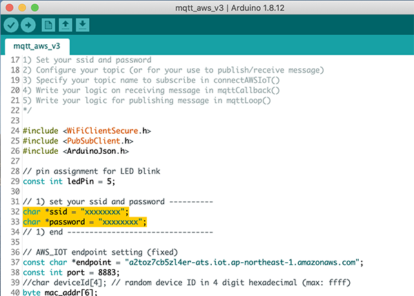
For using this, please update as follows.
1) Set your ssid and password
2) Configure your topic (or for your use to publish/receive message)
3) Specify your topic name to subscribe in connectAWSIoT()
4) Write your logic on receiving message in mqttCallback()
5) Write your logic for publishing message in mqttLoop()
*/
#include <WiFiClientSecure.h>
#include <PubSubClient.h>
#include <ArduinoJson.h>
// pin assignment for LED blink
const int ledPin = 5;
// 1) set your ssid and password ----------
char *ssid = "xxxxxxxx";
char *password = "xxxxxxxx";
// 1) end ---------------------------------
// AWS_IOT endpoint setting (fixed)
const char *endpoint = "a2toz7cb5zl4er-ats.iot.ap-northeast-1.amazonaws.com";
const int port = 8883;
//char deviceId[4]; // random device ID in 4 digit hexadecimal (max: ffff)
byte mac_addr[6];
char deviceId[20];
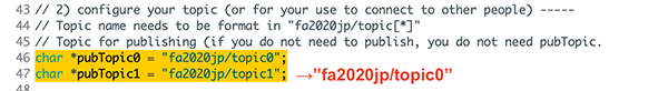
// 2) configure your topic (or for your use to connect to other people) -----
// Topic name needs to be format in "fa2020jp/topic[*]"
// Topic for publishing (if you do not need to publish, you do not need pubTopic.
char *pubTopic0 = "fa2020jp/topic0";
char *pubTopic1 = "fa2020jp/topic1";
// Topic for subscribing
char *subTopic0 = "fa2020jp/topic0";
char *subTopic1 = "fa2020jp/topic1";
// 2) end -----------------------------------------------------------
const char* rootCA = "-----BEGIN CERTIFICATE-----\n" \
***
"-----END CERTIFICATE-----\n";
const char* certificate = "-----BEGIN CERTIFICATE-----\n" \
***
"-----END CERTIFICATE-----\n";
const char* privateKey = "-----BEGIN RSA PRIVATE KEY-----\n" \
***
"-----END RSA PRIVATE KEY-----\n";
WiFiClientSecure httpsClient;
PubSubClient mqttClient(httpsClient);
long randomNumber;
void setup() {
Serial.begin(115200);
pinMode(ledPin, OUTPUT);
// Start WiFi connection
Serial.println("Connecting to ");
Serial.print(ssid);
WiFi.begin(ssid, password);
// wait until WiFi connected
while (WiFi.status() != WL_CONNECTED) {
delay(500);
Serial.print(".");
}
Serial.println("\nWifi Connected.");
// Configure certification and MQTT Client
httpsClient.setCACert(rootCA);
httpsClient.setCertificate(certificate);
httpsClient.setPrivateKey(privateKey);
mqttClient.setServer(endpoint, port);
mqttClient.setCallback(mqttCallback);
// initialize the random number generator with a fairly random input
// randomSeed(analogRead(0));
// Set device Id from Mac Address
WiFi.macAddress(mac_addr);
sprintf(deviceId, "%02X:%02X:%02X:%02X:%02X:%02X", mac_addr[0], mac_addr[1], mac_addr[2], mac_addr[3], mac_addr[4], mac_addr[5]);
connectAWSIoT();
}
void connectAWSIoT() {
while (!mqttClient.connected()) {
// generate device ID in 4 digit hexadecimal (max: ffff)
// generate random decimal max 65536 and convert it to hexadecimal format
// if device ID is dupulicated with the other device, re-generate device ID.
// randomNumber = random(65536);
// ltoa(randomNumber, deviceId, 16);
if (mqttClient.connect(deviceId)) {
Serial.print("mqtt Connected - deviceId: ");
Serial.println(deviceId);
// QoS 0 is sending message only 1 time (the fastest)
// QoS 1 is returning puback to publisher after send message successfully
// QoS 2 is sending message only 1 time with validation (the slowest)
// AWS IoT only allows QoS 0 or 1.
int qos = 0;
// 3) Specify your topic name to subscribe -----------
mqttClient.subscribe(subTopic1, qos);
// 3) end --------------------------------------------
Serial.println("Subscribed.");
} else {
Serial.print("mqttClient.connect() Failed - deviceId:");
Serial.println(randomNumber);
Serial.print("Error state=");
Serial.println(mqttClient.state());
// Wait every 5 seconds until connect to MQTT broker
delay(5000);
}
}
}
long messageSentAt = 0;
int dummyValue = 0;
int dummyValue1 = 0;
char pubMessage0[256];
char pubMessage1[256];
void mqttCallback (char* topic, byte* payload, unsigned int length) {
DynamicJsonDocument doc(256);
// Write serial monitor
Serial.print("Received. topic=");
Serial.println(topic);
// deserialize
DeserializationError error = deserializeJson(doc, payload);
if (error) {
Serial.print("deserializeJson() failed with code ");
Serial.println(error.c_str());
return;
}
// 4) Write your logic on received message -----------------
// blink LED
digitalWrite(ledPin, HIGH);
// dump Json in readable format
serializeJsonPretty(doc, Serial);
Serial.println();
// parse Json (retrieve int value from for each track)
Serial.print("track1: ");
Serial.println(doc["t1"].as<int>());
Serial.print("track2: ");
Serial.println(doc["t2"].as<int>());
Serial.print("track3: ");
Serial.println(doc["t3"].as<int>());
Serial.print("track4: ");
Serial.println(doc["t4"].as<int>());
Serial.print("track5: ");
Serial.println(doc["t5"].as<int>());
// wait for blink LED
delay(200);
digitalWrite(ledPin, LOW);
// 4) end -------------------------------------------------
}
void mqttLoop() {
if (!mqttClient.connected()) {
connectAWSIoT();
}
mqttClient.loop();
// 5) ----- Write your logic for publishing message from here -----
// (If you are not pubishing anything, you can delete following code)
// In this case, send message every 5 seconds.
long now = millis();
if (now - messageSentAt > 3000) {
messageSentAt = now;
// increment dummyValue
dummyValue1 = dummyValue++;
// It looks good to declare JsonDocument in local scope
DynamicJsonDocument doc0(256);
DynamicJsonDocument doc1(256);
// edit data for topic1
doc0["t1"]=dummyValue1; // track1 for topic0
doc0["t2"]=dummyValue++; // track2 for topci0
doc0["t3"]=0; // track2 for topci0
doc0["t4"]=1; // track2 for topci0
doc0["t5"]=2; // track5 for topci0
// edt data for topic2
doc1["t1"]=dummyValue1; // track1 for topic1: same note (at the same time) with doc1(topic1)
doc1["t2"]=dummyValue++; // track2 for topic1
doc1["t3"]=11; // off // track3 for topic1
doc1["t4"]=12; // on // track4 for topic1
doc1["t5"]=13; // track5 for topci1
// serialize Json object to message in byte charactors
serializeJson(doc0, pubMessage0);
serializeJson(doc1, pubMessage1);
Serial.print("Publishing message to topic0 ");
Serial.println(pubTopic0);
Serial.println(pubMessage0);
Serial.print("Publishing message to topic1 ");
Serial.println(pubTopic1);
Serial.println(pubMessage1);
// Publish message to topic
mqttClient.publish(pubTopic0, pubMessage0);
mqttClient.publish(pubTopic1, pubMessage1);
Serial.println("Published.");
}
// 5) end---------------------------------------------------
}
void loop() {
mqttLoop();
}
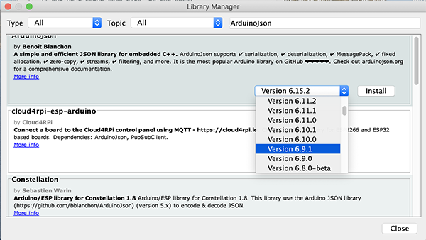
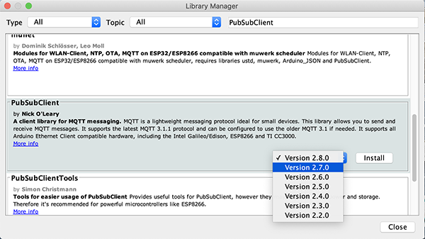
Next, I downloaded [ArduinoJson by Benoit Blanchon (ver 6.9.1)] and [PubSubClient by Nick O’Leary (ver 2.7.0)] from the library.
↓
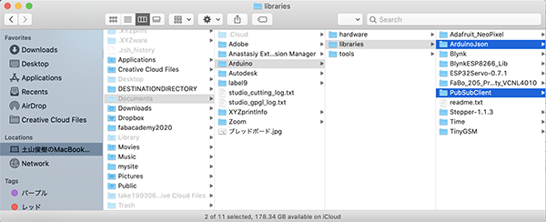
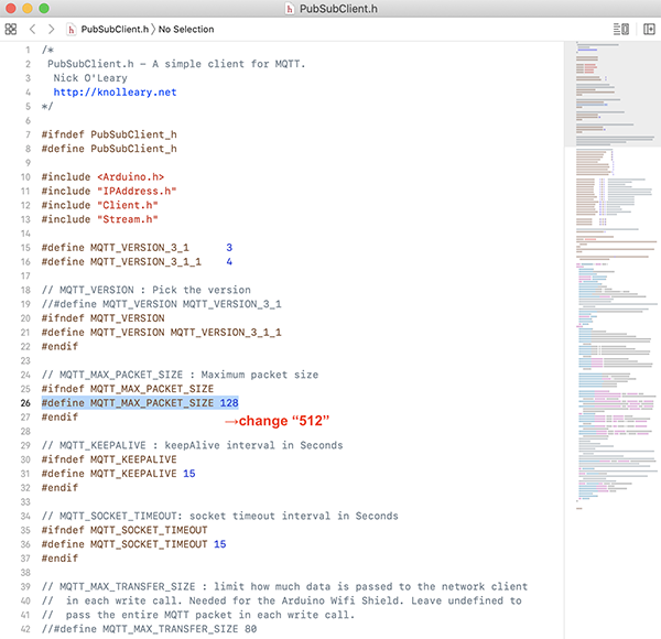
After downloading,Configure max packet size configuration in PubSubClient.h At PubSubClient.h in library, Change [#define MQTT_MAX_PACKET_SIZE 128] to [#define MQTT_MAX_PACKET_SIZE 512]
After that, change the contents of (1) to (4) in the shared code.
In (1), write the SSID and password of Wi-Fi connected to ESP32.
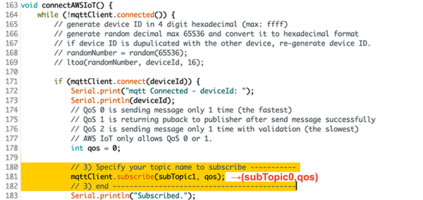
(2) is configure your topic.(or for your use to publish/receive message) This time, both [pubTopic0] and [pubTopic1] are set to [fa2020jp/topic0].
In (3), write the topic name set earlier.
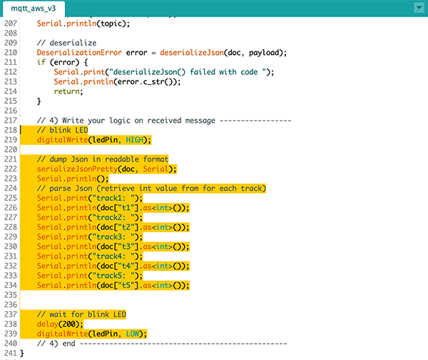
In (4), write the program to move the robot arm.
At the beginning, I just checked if ESP32 can connect to MQTT in my home Wi-Fi environment, so I wrote it in the same state as the first code.
↓
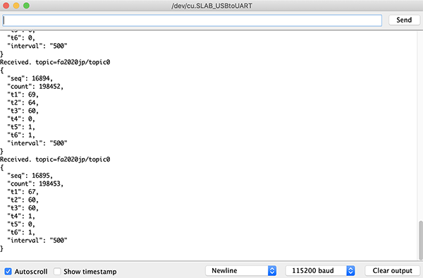
When I checked the serial monitor, I found that I was receiving a signal from MQTT.
Connecting and Controlling the Robot Arm to MQTT
I immediately pasted and wrote the program that moved the robot arm at the location (4) in the MQTT program.
However, the robot arm did not move.
The cause was that [ESP32Servo.h] and the Wi-Fi library could not be synchronized.
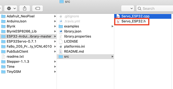
So, I downloaded [Library that can control servo motor in Wi-Fi environment] from the following website.
Control Servo motor using ESP32 over WiFi Push-Return SESP-WiFi-2
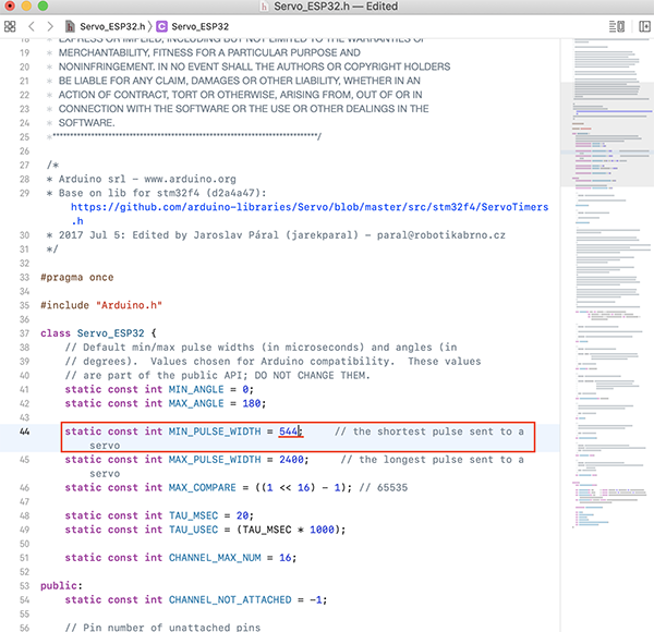
After downloading the library, [static const int MIN_PULSE_WIDTH = 544] of [Servo_ESP32.h] was changed.
The reason is that unless this value is set to 544, the servo motor will not rotate in the range of 0 to 180 degrees.
↓
In addition, after undergoing a rehearsal using zoom, I found that the program I created did not match the sound of other instruments.
So, I created a program that changed the rhythm of the sound to [beat one cup twice in a short time to play the sound].
Programming
#include <Servo_ESP32.h>

/*
 * Description:
 * Example for setting the minimal and maximal angle.
 */

static const int servo1Pin = 12;//printed G14 on the board


Servo_ESP32 servo1;

/*
This is a sample template program for ESP32 connecting to
AWS IoT over MQTT to make distributed machine device for group
project of Machine design and mechanial design in
FabAcademy 2020 (students at Fablab Kamakura and Kannai).

As this code contains certification information, PLEASE
DO NOT UPLOAD THIS SOURCE CODE to ANY SHARABLE PLACE
DIRECTLY(including FabAcademy page). If you need to upload
this to sharable place, PLEASE MAKE SURE YOU DELETE
VALUES OF rootCA, certificate and privateKey CHARACTORS.

For preparation, please find PubSubClient.h in youf local
library and chhange #define MQTT_MAX_PACKET_SIZE 128 to 512.

For using this, please update as follows.
1) Set your ssid and password
2) Configure your topic (or for your use to publish/receive message)
3) Specify your topic name to subscribe in connectAWSIoT()
4) Write your logic on receiving message in mqttCallback()
5) Write your logic for publishing message in mqttLoop()  // <-optional
*/

#include <WiFiClientSecure.h>
#include <PubSubClient.h>
#include <ArduinoJson.h>

#include <ESPmDNS.h>


// pin assignment for LED blink
//const int S1 = 4;
//const int S2 = 16;
//const int S3 = 17;

// 1) set your ssid and password ----------
char *ssid = "Buffalo-G-B378";
char *password = "5h4drrvjjmift";
// 1) end ---------------------------------

// AWS_IOT endpoint setting (fixed)
const char *endpoint = "a2toz7cb5zl4er-ats.iot.ap-northeast-1.amazonaws.com";
const int port = 8883;
//char deviceId[4]; // random device ID in 4 digit hexadecimal (max: ffff)
byte mac_addr[6];
char deviceId[20];

// 2) configure your topic (or for your use to connect to other people) -----
// Topic name needs to be format in "fa2020jp/topic[*]"
// Topic for publishing (if you do not need to publish, you do not need pubTopic.
char *pubTopic0 = "fa2020jp/topic0";

// Topic for subscribing
char *subTopic0 = "fa2020jp/topic0";

// 2) end -----------------------------------------------------------

const char* rootCA = "-----BEGIN CERTIFICATE-----\n" \
***
"-----END CERTIFICATE-----\n";

const char* certificate = "-----BEGIN CERTIFICATE-----\n" \
***
"-----END CERTIFICATE-----\n";

const char* privateKey = "-----BEGIN RSA PRIVATE KEY-----\n" \
***
"-----END RSA PRIVATE KEY-----\n";

WiFiClientSecure httpsClient;
PubSubClient mqttClient(httpsClient);


void setup() {
    Serial.begin(115200);
    pinMode(12, OUTPUT);

    // Start WiFi connection
    Serial.println("Connecting to ");
    Serial.print(ssid);
    WiFi.begin(ssid, password);

    // wait until WiFi connected
    while (WiFi.status() != WL_CONNECTED) {
        delay(500);
        Serial.print(".");
    }
    Serial.println("\nWifi Connected.");

    // Configure certification and MQTT Client
    httpsClient.setCACert(rootCA);
    httpsClient.setCertificate(certificate);
    httpsClient.setPrivateKey(privateKey);
    mqttClient.setServer(endpoint, port);
    mqttClient.setCallback(mqttCallback);

    // Set device Id from Mac Address
    WiFi.macAddress(mac_addr);
    sprintf(deviceId, "%02X:%02X:%02X:%02X:%02X:%02X", mac_addr[0], mac_addr[1], mac_addr[2], mac_addr[3], mac_addr[4], mac_addr[5]);

    connectAWSIoT();
    servo1.attach(servo1Pin);


}

void connectAWSIoT() {
    while (!mqttClient.connected()) {

        if (mqttClient.connect(deviceId)) {
            Serial.print("mqtt Connected - deviceId: ");
            Serial.println(deviceId);
            // QoS 0 is sending message only 1 time (the fastest)
            // QoS 1 is returning puback to publisher after send message successfully
            // QoS 2 is sending message only 1 time with validation (the slowest)
            // AWS IoT only allows QoS 0 or 1.
            int qos = 0;

            // 3) Specify your topic name to subscribe -----------
            mqttClient.subscribe(subTopic0, qos);
            // 3) end --------------------------------------------
            Serial.println("Subscribed.");
        } else {
            Serial.print("mqttClient.connect() Failed - deviceId:");
            Serial.println(deviceId);
            Serial.print("Error state=");
            Serial.println(mqttClient.state());
            // Wait every 5 seconds until connect to MQTT broker
            delay(5000);
        }
    }
}


int t4;
int t5;
int t6;

void mqttCallback(char* topic, byte* payload, unsigned int length) {
    DynamicJsonDocument doc(256);

    // Write serial monitor
    Serial.print("Received. topic=");
    Serial.println(topic);

    // deserialize
    DeserializationError error = deserializeJson(doc, payload);
    if (error) {
        Serial.print("deserializeJson() failed with code ");
        Serial.println(error.c_str());
        return;
    }

    // 4) Write your logic on received message -----------------

    // dump Json in readable format
    serializeJsonPretty(doc, Serial);
    Serial.println();
    // parse Json (retrieve int value from for each track)

    int seq = doc["seq"].as<int>();
    int interval = doc["interval"].as<int>();
    int overhead; // overhead for each beat (returned by pushSolenoids())

//    int t1 = doc["t1"].as<int>();
//    int t2 = doc["t2"].as<int>();
//    int t3 = doc["t3"].as<int>();
//    int t4 = doc["t4"].as<int>();
//    int t5 = doc["t5"].as<int>();
//    int t6 = doc["t6"].as<int>();

//    switch (t4) {
//        case 0:
          delay(400);
          servo1.write(20);
          delay(100);
          servo1.write(70);
          delay(100);
          servo1.write(20);
          delay(100);
          servo1.write(70);
          delay(100);
//        break;

//        case 1:
//        break;

//    }

    // 4) end -------------------------------------------------
}


void mqttLoop() {
    if (!mqttClient.connected()) {
        connectAWSIoT();
    }
    mqttClient.loop();

    // 5) ----- Write your logic for publishing message from here -----
    // (If you are not pubishing anything, you can delete following code)

    // Publisher publishes folowing element
    // seq: sequence status (start from 1 when start sound)
    // count: count (start from 1 when start publisher process (on Node-RED in RaspPi)
    // t1: melody1 (in MIDI note name)
    // t2: melody2 (ex. harmony, in MIDI note name)
    // t3: code,  (in MIDI note name)
    // t4: rhythm1 (8 beat, front)       1, 0, 1, 0, 1, 0, 1, 0
    // t5: rhythm2 (8 beat, back)        0, 1, 0, 1, 0, 1, 0, 1
    // t6: rhythm3 (8 beat, variation)   1, 1, 0, 1, 0, 1, 1, 0
    // interval: interval in delay

//    mqttClient.disconnect();
    // 5) end---------------------------------------------------
}


void loop() {
   // server.handleClient();
  mqttLoop();
}
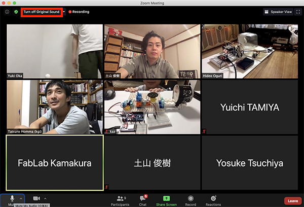
Orchestra Rehearsal
We performed dozens of rehearsals to improve the quality of the ensemble.
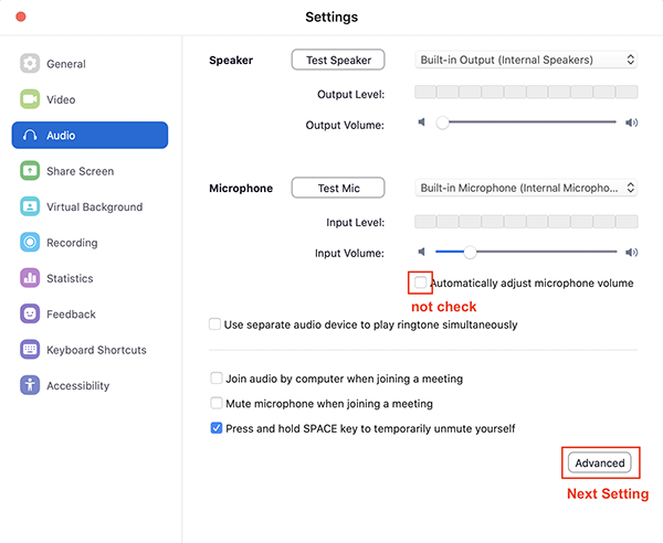
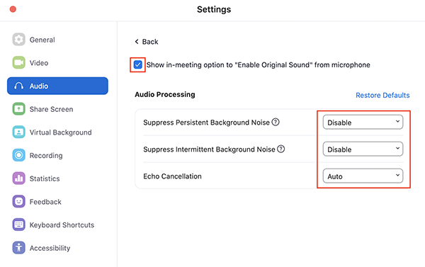
We have made detailed settings for the audio within the zoom in order to evenly share the sounds each plays on the zoom.
- Uncheck [Automatically adjust microphone volume]
- [Suppress Persistent Background Noise]→[Disable]
- [Suppress Intermittent Background Noise]→[Disable]
- [Echo Cancellation]→[Auto]
- Confirm that [Turn Off Original Sound] is set
Among them, I changed the glass that the robot arm hits from glass to metal so that it would not interfere with the sound quality of other performers.
↓
5. Description of Important Weekly Learning Outcome
This time, I controlled the servo motor of the robot arm with ESP32 and used it for the mechanism of [Sound making instrument].
This time, I downloaded multiple libraries to use ESP32, but I was surprised to find the code for when I want to operate the servo motor in the Wi-Fi environment.
Also, I was able to launch an interesting project by controlling a machine I created using a program called MQTT.
I wanted to develop this project further and do a machine orchestra with people all over the world.
6. Links to Files and Code
- Robotarm parts [pdf]
- Fix parts [pdf]
- Additional parts for performance [pdf]
- Foundation [pdf]
- ESP32 LED [ino]
- ESP32 servo 90deg [ino]
- ESP32 servo [ino]
- ESP32 servo & potentionmeter(1) [ino]
- ESP32 servo & potentionmeter(2) [ino]
- ESP32 servo rhythm(1) [ino]
- ESP32 servo rhythm(2) [ino]
- MQTT FMT [ino]
- MQTT mypart [ino]
7. Appendix
None