- Breadboard Prototyping & Programming
1. Weekly Brief Summary
This week I designed a circuit for a glowing accessory on a breadboard and created a program to control the device.
2. Description of Assignment Work
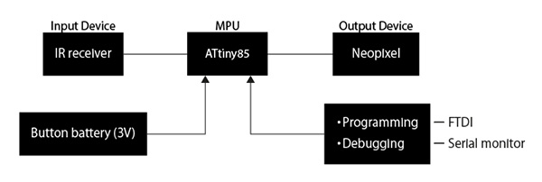
I made a list of the features I needed for the earrings and obi clasp and created a block diagram to go with it.
I also selected the electronic components to be used (the selection criteria were that they must be in stock in the lab and easily available in Japan).
We then used a breadboard to create a circuit based on the datasheet of the MPU to be used.
We worked with the program, checking each sensor to be used one by one, in parallel with the program, and finally merged the programs we had created.
Earrings side
Function
- ATtiny85
- Infrared Reception
- LED lighting
- Power Supply
- Program Writing
- Debugging
↓
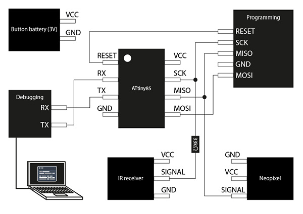
Block Diagram
Electronic components used
| component | vender | cost(JPY) | quanitity | total | notes |
|---|---|---|---|---|---|
| ATtiny85 | Akitsukidenshi | ¥130 | 1 | ¥130 | shop link |
| Built-in microcomputerputerized full-color tape LED 1m 30LED IP65 with SK6812 | Akitsukidenshi | ¥900 | 1 | ¥900 | shop link |
| Infrared remote control module for Arduino Raspberry Pi with IR HX1838 receiver module kit | Akitsukidenshi | ¥350 | 1 | ¥350 | shop link |
| Carbon Resistor (Carbon Film Resistor) 1/6W33kΩ (100 pcs.) | Akitsukidenshi | ¥100 | 1 | ¥100 | shop link |
- 33kΩ・・・Countermeasures for Clock
① ATtiny85
I chose the ATtiny85 as the MPU to control the earring lighting. The reason is that it has a larger capacity than the ATtiny45. And I decided to allocate 2 of the 8 bits to the Neopixel brightness setting and the remaining 4 bits to the color setting.
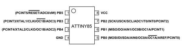
I have checked the ATtiny85 datasheet I use.
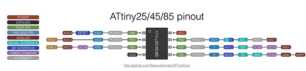
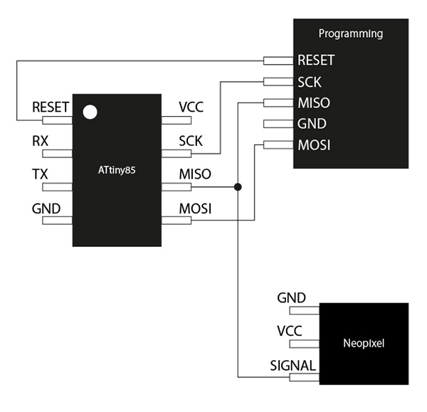
First, I checked the pin configuration of the ATtiny85. There are 8 pins in total, 4 (GND) and 8 (VCC) are used for power supply. This time, I used the Fabtiny I created in week4to write the program. Assign 1 (RESET), 5 (MOSI), 6 (MISO) and 7 (SCK) for use. Assign 3 (RX) and 4 (TX) to be used for debugging.
Initial configuration of ATtiny85
When the ATtiny85 is new, the operating frequency is set to 1MHz, so you need to switch it to 8MHz. Connect ATtiny85 to Fabtiny and do [Burn Bootloader] with Arduino.
Setting details
- Board:”ATtiny25/45/85”
- Processor:”ATtiny85”
- Clock:”Internal 8 MHz”
- Programmer:”USBtinyISP”
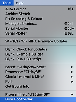
This allows you to write programs to ATtiny85.
② IR Receiver
Infrared remote control communication format
An infrared remote control is a wireless control system that uses the 900 nm band of infrared radiation as a carrier and is commonly used in home appliances. The communication formats often used include NEC, KASEIKYO, and SONY formats, and most home appliances in Japan are covered by these three types. The carrier wavelength (800nm band) used in the infrared data communication standard IrDA is different from the remote control.
- Carrier: Infrared (λp = 950nm)
- Subcarrier: fsc = 38kHz, 1/3duty
- T(modulation unit) = 562μs
- Fixed Length Frame (32bit)
- 16-bit customer code
- 8-bit data + 8-bit inverted data
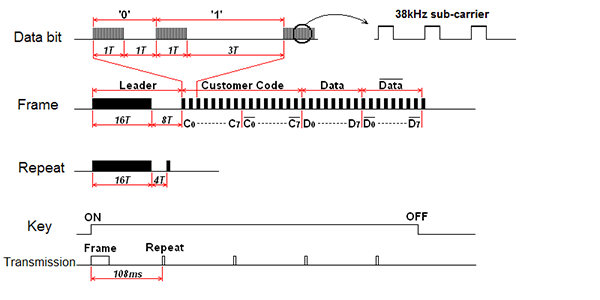
- Leader: A synchronization pattern that indicates the start of a frame, also known as an AGC burst, which is responsible for setting the gain of the receiver circuitry appropriately.
- Customer Code: A manufacturer’s identification code. Renesas Electronics manages and assigns these codes. In early specifications, this was an 8-bit code plus an 8-bit inverted code, just like the data section. Later, the specification was changed to 16-bit code.
- Data: 8-bit control data and its bit-reversed value are sent. Check it for errors.
- Repeat: After the frame, the frame is sent in 108ms cycles while the button is held down. The purpose of this is to reduce power consumption and make it easier to identify a series of button presses, and to prevent doubling at times of reception uncertainty. There are some transmitters that do not emit this and send the frame repeatedly.
Circuitry and programming for the infrared receiver
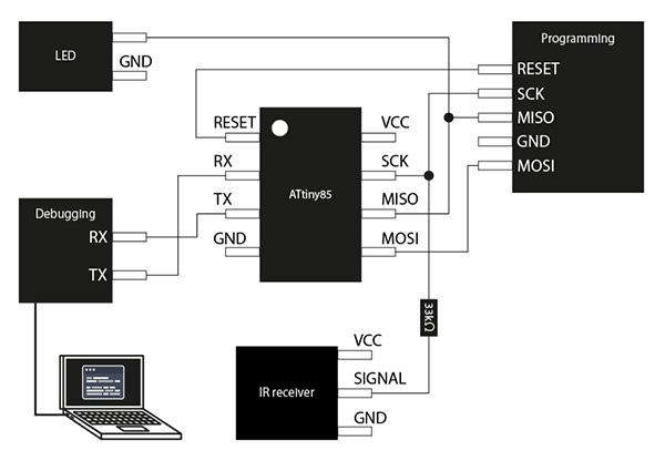
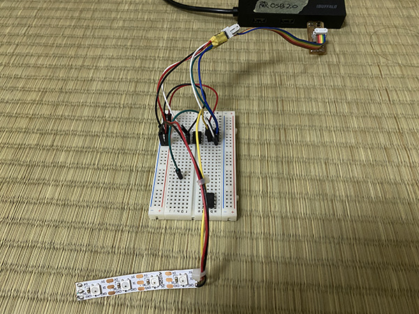
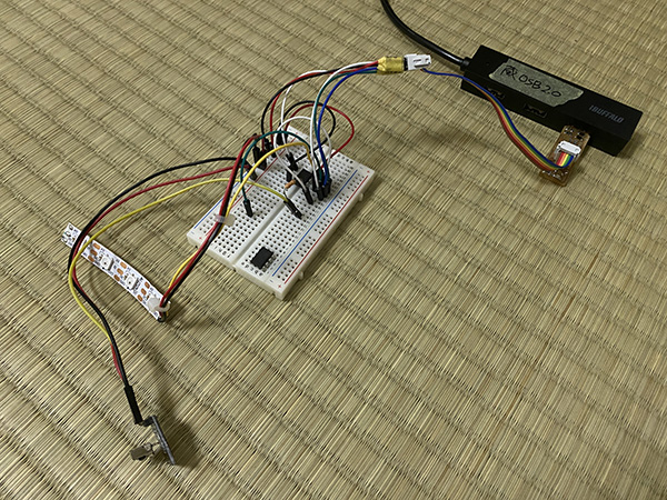
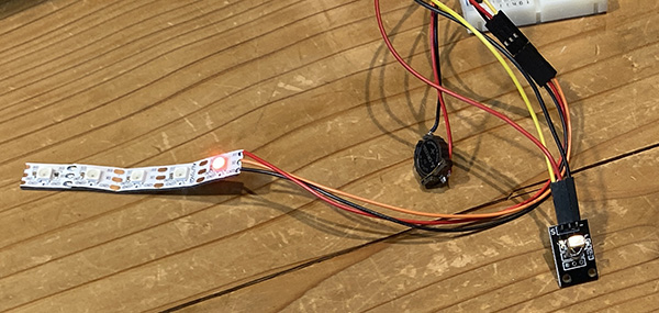
I first assembled and programmed the circuitry for the ATtiny85 and the infrared receiver on a breadboard.
I researched the case of controlling IR receiver using ATtiny85 and made a breadboard and program based on the circuit diagram in the following image.
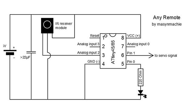
However, the 3 pins that use the IR receiver in the image will be used for RX in this case. So I decided to connect the signal line of the IR receiver to pin 7. The LED is connected to pin 6. And I used 33kΩ for clock measure.
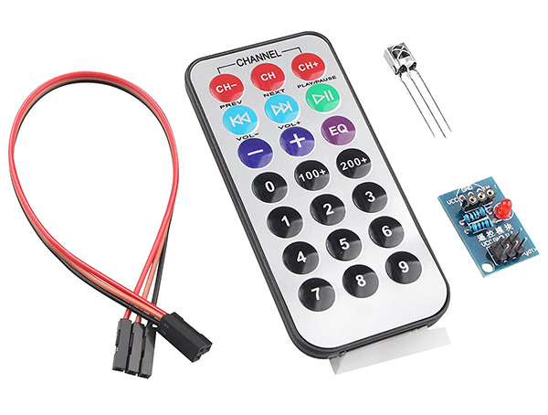
HX1838 receiver module kit + infrared remote control module
We used HX1838 receiver module kit + infrared remote control module for the infrared receiver breadboard circuitry. Compatible - Raspberry/dp/B07KFCCSYN) and is an Arduino compatible kit.
breadboard diagram
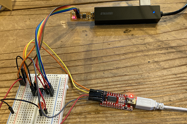
breadboard photo
ATtiny85 infrared receiver program
I wrote a program based on “How to receive infrared light on the ATtiny85 without using any libraries” from Infrared reception on the ATtiny85. I wrote the following sketch in ATtiny85 with 1MHz clock and checked the operation. The serial output port of ATtiny85 is assigned to PB0.
Programming
/* ATtiny85 IR Remote Control Receiver

   David Johnson-Davies - www.technoblogy.com - 3rd April 2015
   ATtiny85 @ 1 MHz (internal oscillator; BOD disabled)

   CC BY 4.0
   Licensed under a Creative Commons Attribution 4.0 International license:
   http://creativecommons.org/licenses/by/4.0/

   http://www.technoblogy.com/show?V6F

*/

volatile int NextBit;
volatile unsigned long RecdData;
int Brightness;

// Demo routine
void ReceivedCode(boolean Repeat) { //19~26行目・・・デモプログラムの表示部分(シリアルで表示する部分)表示処理(19行目)の場所→37,43行目
//  char buff[64];
//  sprintf(buff,"%d,%x",Repeat,RecdData);
//  mySerial.println(buff);
  Serial.print(Repeat);
  Serial.print(",");
  Serial.println(RecdData,HEX);
}


// Interrupt service routine - called on every falling edge of PB2(割り込み処理のプログラム)
ISR(INT0_vect) {
  int Time = TCNT0;
  int Overflow = TIFR & 1<<TOV0;
  // Keep looking for AGC pulse and gap
  if (NextBit == 32) { //NextBitの32はどんどん減って最終的には0になり、32に戻る
    if ((Time >= 194) && (Time <= 228) && (Overflow == 0)) { //ATtiny85の中に入っているタイマー。
      RecdData = 0; NextBit = 0;
    } else if ((Time >= 159) && (Time <= 193) && (Overflow == 0)) ReceivedCode(1);
  // Data bit
  } else {
    if ((Time > 44) || (Overflow != 0)) NextBit = 32; // Invalid - restart
    else {
      if (Time > 26) RecdData = RecdData | ((unsigned long) 1<<NextBit);
      if (NextBit == 31) ReceivedCode(0);
      NextBit++;
    }
  }
  TCNT0 = 0;                  // Clear counter
  TIFR = TIFR | 1<<TOV0;      // Clear overflow
  GIFR = GIFR | 1<<INTF0;     // Clear INT0 flag
}

// Setup **********************************************

void setup() {
  // Set up Timer/Counter0 (assumes 1MHz clock)
  TCCR0A = 0;                 // No compare matches
  TCCR0B = 3<<CS00;           // Prescaler /64
  // Set up INT0 interrupt on PB2
  MCUCR = MCUCR | 2<<ISC00;   // Interrupt on falling edge
  GIMSK = GIMSK | 1<<INT0;    // Enable INT0
  NextBit = 32;               // Wait for AGC start pulse

  Serial.begin(9600);
  Serial.println("ATtiny 85 IR Receive demo start");
}

void loop() {
}
I ran the sketch and fired the remote control at the IR receiver. I was able to confirm that the IR receiver was responding when I pressed the [1] button on the remote control.
③ Serial Console for Mac Debugging
I decided to use the Mac version of the serial monitor for debugging the infrared communication. This can be connected serially by entering the Terminal command.
(1) Without connecting the FTDI cable to your Mac, do the following
$ ls -l /dev/tty.*
crw-rw-rw-  1 root  wheel   18,   0  6 10 02:13 /dev/tty.Bluetooth-Incoming-Port
crw-rw-rw-  1 root  wheel   18,   2  6 10 02:13 /dev/tty.Bluetooth-Modem
At this point, make sure the FTDI cable is not connected.
(2) Connect the FTDI cable to your Mac
(3) Check the name of the connected FTDI cable
$ ls -l /dev/tty.*
crw-rw-rw-  1 root  wheel   18,   0  6 10 02:13 /dev/tty.Bluetooth-Incoming-Port
crw-rw-rw-  1 root  wheel   18,   2  6 10 02:13 /dev/tty.Bluetooth-Modem
crw-rw-rw-  1 root  wheel   18,   8  6 10 12:13 /dev/tty.usbmodem1421
(4) Check the FTDI cable
You can confirm that /dev/tty.usbmodem1421 has been added by the operation (3). This microcontroller (tty device) is usbmodem1421.
(5) Execute the cu command $ cu -l /dev/tty. “tty device name”.
$ cu -l /dev/tty.usbmodem1421
Connected.
(5)’ If you are unable to connect to the cable
If you can’t connect to the cable after entering the above code, enter the command again with root privileges.
$ sudo cu -l /dev/tty.usbmodem1421
Connected.
(6) Entering the screen command
Enter a command to display the serial monitor.
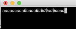
$ screen /dev/tty.KeySerial1
I checked the program I mentioned earlier on the serial console and found that the button presses read “a”. However, some of it was garbled, so I found it to be unreliable as a serial monitor.
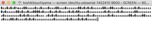
So I decided to install “iTerm2 *recommended configuration reference site
However, the garbling was not resolved as well.
(7) Getting out of the serial console
(1) Press [control] + [A].
(2) Hold [control] and release [A]
.
(3) Press [¥].
(4) Really quit and kill all your windows [y/n] is displayed, enter [y].
④ATtiny85 SoftwareSerial Test Program
Next I created a program for debugging. You don’t need to download [SoftwareSerial.h], the standard library is fine.
Programming
//-------------------------------------------------------------------------------------------------------------------
//
// ATtiny85 SoftwareSerial test program
//    2020.5.28
//  Softserial04.ino
//
//   Terminal Soft Setting
//      Enter code  RX : CR+LF
//                  TX : CR
//

#include <SoftwareSerial.h>

int led = 1; // PB1(Pin6)

SoftwareSerial mySerial(3, 4); // RX(PB3:Pin2), TX(PB4:Pin3)
void setup() {
  // initialize the digital pin as an output.
  pinMode(led, OUTPUT);
  mySerial.begin(9600);
  delay(500);
  mySerial.println("Serial connect");

}

// the loop routine runs over and over again forever:
void loop() {
  if (mySerial.available()) {
      while(mySerial.available()){
        char RXdata = mySerial.read();
        mySerial.write(RXdata);
      }
    digitalWrite(led, HIGH); //下記4行はなくてもいい
    delay(100);
     digitalWrite(led, LOW);
    delay(50);
  }
}

//---------------
ATtiny85
TX (PB4:Pin3) → FTDI RX
RX (PB3:Pin2) → FTDI TX
FTDI Baudrate → 9600

Echo back the data sent by PC terminal software
Pin 6 LED lights up for 100ms
⑤ATtiny85 + IR Receiver + SoftwareSerial Test Program
I merged the serial console program and the infrared receiver program I have created so far to see if the serial console could display the information received in the infrared.
Programming
//-------------------------------------------------------------------------------------------------------------------------
/*
 *  IrDA receive data print program
 *    IRreceive_print01.ino
 *      2020.5.28

 * Original Scketch
   ATtiny85 IR Remote Control Receiver
   David Johnson-Davies - www.technoblogy.com - 3rd April 2015
   ATtiny85 @ 1 MHz (internal oscillator; BOD disabled)
   CC BY 4.0
   Licensed under a Creative Commons Attribution 4.0 International license:
   http://creativecommons.org/licenses/by/4.0/
*/

#include <SoftwareSerial.h>

SoftwareSerial mySerial(3, 4); // RX(PB3:Pin2), TX(PB4:Pin3)

// LED outputs
int LED = 1;   // LED indicator PB1(Pin6)

volatile int NextBit;
volatile unsigned long RecdData;
volatile int Rcvflag = 0;
volatile int RcvDATA;

char HEXprint[] = {'0','1','2','3','4','5','6','7','8','9','A','B','C','D','E','F'} ;

// Setup **********************************************

void setup() {
  // Set up LEDs
  pinMode(LED, OUTPUT);

  // initialize Serial Port
  mySerial.begin(9600);
  delay(500);
  mySerial.println("Serial connect");

  // Set up Timer/Counter0 (assumes 8MHz clock)
  TCCR0A = 0;                 // No compare matches
  TCCR0B = 5<<CS00;           // Prescaler set
  // Set up INT0 interrupt on PB2
  MCUCR = MCUCR | 2<<ISC00;   // Interrupt on falling edge
  GIMSK = GIMSK | 1<<INT0;    // Enable INT0
  NextBit = 32;               // Wait for AGC start pulse
}

void loop() {
  if (Rcvflag != 0){
    Rcvflag = 0;
    char Pdata = (RcvDATA & 0xF0)>>4 ; // pickup upper 4 bits
    mySerial.print(HEXprint[Pdata]);   // print in HEX
    Pdata = (RcvDATA & 0x0F);          // pickup lower 4 bits
    mySerial.println(HEXprint[Pdata]); // print in HEX
    digitalWrite(LED, 1);  // indicator LED blink
    delay(100);
    digitalWrite(LED, 0);
  }
}

// *** Interrupt service routine - called on every falling edge of PB2 ***

ISR(INT0_vect) {
  int Time = TCNT0;
  int Overflow = TIFR & 1<<TOV0;
  // Keep looking for AGC pulse and gap
  if (NextBit == 32) {
    if ((Time >= 87) && (Time <= 114) && (Overflow == 0)) {
      RecdData = 0; NextBit = 0;
    } else if ((Time >= 80) && (Time <= 97) && (Overflow == 0)) ReceivedCode(1);
  // Data bit
  } else {
    if ((Time > 22) || (Overflow != 0)) NextBit = 32; // Invalid - restart
    else {
      if (Time > 13) RecdData = RecdData | ((unsigned long) 1<<NextBit);
      if (NextBit == 31) ReceivedCode(0);
      NextBit++;
    }
  }
  TCNT0 = 0;                  // Clear counter
  TIFR = TIFR | 1<<TOV0;      // Clear overflow
  GIFR = GIFR | 1<<INTF0;     // Clear INT0 flag
}

// Main Process after IrDA data received
void ReceivedCode(boolean Repeat) {
  // Check for correct remote control
  if ((RecdData & 0xFFFF) != 0xff00) return; // check the maker_code 0xFF
  // Read key pressed
  RcvDATA = RecdData>>16 & 0xFF;

  // Set DATA receivedflag for SerialPrint
  Rcvflag = 1;

}
ATtiny85
TX (PB4:Pin3) → FTDI RX
RX (PB3:Pin2) → FTDI TX
FTDI Baudrate → 9600
IrDA receiver (PB2 : Pin7) → thrugh 330ohm
LED (PB1 : Pin6)

Print out the data received by the infrared remote control with HEX
The LED blinks when it is successfully received.
I made a list beforehand of what letters appear on the serial console when I press the numbers 0-7 on the remote control, respectively. I was then able to see on the serial console that I was pressing “1” and “0” on the remote control.
| Button Number | Text |
|---|---|
| 0 | 16 |
| 1 | 0C |
| 2 | 18 |
| 3 | 5E |
| 4 | 08 |
| 5 | 1C |
| 6 | 5A |
| 7 | 42 |
| 8 | 52 |
| 9 | 4A |
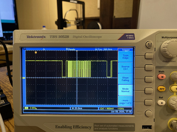
I also confirmed that the waveforms of the microscope followed the waveforms of the infrared communication.
- 100ms display
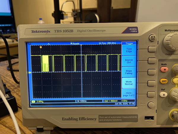
- 25ms display
⑥ Neopixel
I decided to use Neopixel for the earring lighting. The reason for this is because I wanted to be able to set multiple patterns of how the earrings glow. With Neopixel, I think it will be an accessory that can be worn for various occasions, as it can produce light in RGB colors.
I researched the case of controlling Neopixel with ATtiny85 and made a breadboard and program based on the schematic of the following image.
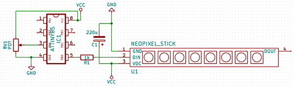
But this time, I connected the signal line of Neopixel to 6 pins. Unlike normal LEDs, you don’t need to prepare a resistor because it is already built in Neopixel.
breadboard diagram
breadboard photo
Neopixel sample code
I first wrote a sample program controlling the Neopixel to the ATtiny85 to see if it worked.
Programming
#include <Adafruit_NeoPixel.h>
#ifdef __AVR__
  #include <avr/power.h>
#endif

#define PIN 1

// Parameter 1 = number of pixels in strip
// Parameter 2 = Arduino pin number (most are valid)
// Parameter 3 = pixel type flags, add together as needed:
//   NEO_KHZ800  800 KHz bitstream (most NeoPixel products w/WS2812 LEDs)
//   NEO_KHZ400  400 KHz (classic 'v1' (not v2) FLORA pixels, WS2811 drivers)
//   NEO_GRB     Pixels are wired for GRB bitstream (most NeoPixel products)
//   NEO_RGB     Pixels are wired for RGB bitstream (v1 FLORA pixels, not v2)
//   NEO_RGBW    Pixels are wired for RGBW bitstream (NeoPixel RGBW products)
Adafruit_NeoPixel strip = Adafruit_NeoPixel(1, PIN, NEO_GRB + NEO_KHZ800);

// IMPORTANT: To reduce NeoPixel burnout risk, add 1000 uF capacitor across
// pixel power leads, add 300 - 500 Ohm resistor on first pixel's data input
// and minimize distance between Arduino and first pixel.  Avoid connecting
// on a live circuit...if you must, connect GND first.

void setup() {
  // This is for Trinket 5V 16MHz, you can remove these three lines if you are not using a Trinket
  #if defined (__AVR_ATtiny85__)
    if (F_CPU == 16000000) clock_prescale_set(clock_div_1);
  #endif
  // End of trinket special code

  strip.begin();
  strip.setBrightness(50);
  strip.show(); // Initialize all pixels to 'off'
}

void loop() {
  // Some example procedures showing how to display to the pixels:
  colorWipe(strip.Color(255, 0, 0), 50); // Red
  colorWipe(strip.Color(0, 255, 0), 50); // Green
  colorWipe(strip.Color(0, 0, 255), 50); // Blue
//colorWipe(strip.Color(0, 0, 0, 255), 50); // White RGBW
  // Send a theater pixel chase in...
  theaterChase(strip.Color(127, 127, 127), 50); // White
  theaterChase(strip.Color(127, 0, 0), 50); // Red
  theaterChase(strip.Color(0, 0, 127), 50); // Blue

  rainbow(20);
  rainbowCycle(20);
  theaterChaseRainbow(50);
}

// Fill the dots one after the other with a color
void colorWipe(uint32_t c, uint8_t wait) {
  for(uint16_t i=0; i<strip.numPixels(); i++) {
    strip.setPixelColor(i, c);
    strip.show();
    delay(wait);
  }
}

void rainbow(uint8_t wait) {
  uint16_t i, j;

  for(j=0; j<256; j++) {
    for(i=0; i<strip.numPixels(); i++) {
      strip.setPixelColor(i, Wheel((i+j) & 255));
    }
    strip.show();
    delay(wait);
  }
}

// Slightly different, this makes the rainbow equally distributed throughout
void rainbowCycle(uint8_t wait) {
  uint16_t i, j;

  for(j=0; j<256*5; j++) { // 5 cycles of all colors on wheel
    for(i=0; i< strip.numPixels(); i++) {
      strip.setPixelColor(i, Wheel(((i * 256 / strip.numPixels()) + j) & 255));
    }
    strip.show();
    delay(wait);
  }
}

//Theatre-style crawling lights.
void theaterChase(uint32_t c, uint8_t wait) {
  for (int j=0; j<10; j++) {  //do 10 cycles of chasing
    for (int q=0; q < 3; q++) {
      for (uint16_t i=0; i < strip.numPixels(); i=i+3) {
        strip.setPixelColor(i+q, c);    //turn every third pixel on
      }
      strip.show();

      delay(wait);

      for (uint16_t i=0; i < strip.numPixels(); i=i+3) {
        strip.setPixelColor(i+q, 0);        //turn every third pixel off
      }
    }
  }
}

//Theatre-style crawling lights with rainbow effect
void theaterChaseRainbow(uint8_t wait) {
  for (int j=0; j < 256; j++) {     // cycle all 256 colors in the wheel
    for (int q=0; q < 3; q++) {
      for (uint16_t i=0; i < strip.numPixels(); i=i+3) {
        strip.setPixelColor(i+q, Wheel( (i+j) % 255));    //turn every third pixel on
      }
      strip.show();

      delay(wait);

      for (uint16_t i=0; i < strip.numPixels(); i=i+3) {
        strip.setPixelColor(i+q, 0);        //turn every third pixel off
      }
    }
  }
}

// Input a value 0 to 255 to get a color value.
// The colours are a transition r - g - b - back to r.
uint32_t Wheel(byte WheelPos) {
  WheelPos = 255 - WheelPos;
  if(WheelPos < 85) {
    return strip.Color(255 - WheelPos * 3, 0, WheelPos * 3);
  }
  if(WheelPos < 170) {
    WheelPos -= 85;
    return strip.Color(0, WheelPos * 3, 255 - WheelPos * 3);
  }
  WheelPos -= 170;
  return strip.Color(WheelPos * 3, 255 - WheelPos * 3, 0);
}
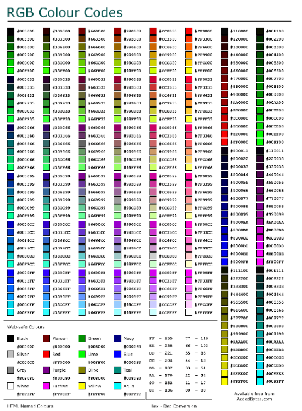
Changing Neopixel’s color settings
The information (0-7 numbers) sent from the remote control (infrared transmitter) is read into ATtiny85. The program was created by replacing the sent characters with the Neopixel color code.
| Button Number | Text |
|---|---|
| 0 | 16 |
| 1 | 0C |
| 2 | 18 |
| 3 | 5E |
| 4 | 08 |
| 5 | 1C |
| 6 | 5A |
| 7 | 42 |
| 8 | 52 |
| 9 | 4A |
At first, I defined a variable [int c] to set Neopixel’s color code, but [int] couldn’t be used in this program because it is a signed 24-bit integer. But [int] is a signed 24-bit integer, so I couldn’t use it in this program. So I solved this problem by using the unsigned [Uint32_t c] (U=unsinde).
In addition, the color codes used in Neopixel alone have been changed to the following notations.
| Before Change | After Change |
|---|---|
| colorWipe(strip.Color(255, 0, 0), 50); // Red | FF0000 |
| colorWipe(strip.Color(0, 255, 0), 50); // Green | 00FF00 |
| colorWipe(strip.Color(0, 0, 255), 50); // Blue | 0000FF |
breadboard diagram
breadboard photo
Programming
//-------------------------------------------------------------------------------------------------------------------------
/*
 *  IrDA receive data print program
 *    IRreceive_print01.ino
 *      2020.5.28

 * Original Scketch
   ATtiny85 IR Remote Control Receiver
   David Johnson-Davies - www.technoblogy.com - 3rd April 2015
   ATtiny85 @ 1 MHz (internal oscillator; BOD disabled)
   CC BY 4.0
   Licensed under a Creative Commons Attribution 4.0 International license:
   http://creativecommons.org/licenses/by/4.0/
*/

#include <SoftwareSerial.h>//ソフトウェアシリアルの設定を追記
SoftwareSerial mySerial(3, 4); // RX(PB3:Pin2), TX(PB4:Pin3) ソフトウェアシリアルの設定を追記

// LED outputs
int LED = 1;   // LED indicator PB1(Pin6)

volatile int NextBit;
volatile unsigned long RecdData;
volatile int Rcvflag = 0; //受信フラグ
volatile int RcvDATA; //32bitのデータを収納する変数

char HEXprint[] = {'0','1','2','3','4','5','6','7','8','9','A','B','C','D','E','F'} ;

//ネオピクセル
#include <Adafruit_NeoPixel.h>
#ifdef __AVR__
#include <avr/power.h>
#endif

#define PIN 1

// Parameter 1 = number of pixels in strip
// Parameter 2 = Arduino pin number (most are valid)
// Parameter 3 = pixel type flags, add together as needed:
//   NEO_KHZ800  800 KHz bitstream (most NeoPixel products w/WS2812 LEDs)
//   NEO_KHZ400  400 KHz (classic 'v1' (not v2) FLORA pixels, WS2811 drivers)
//   NEO_GRB     Pixels are wired for GRB bitstream (most NeoPixel products)
//   NEO_RGB     Pixels are wired for RGB bitstream (v1 FLORA pixels, not v2)
//   NEO_RGBW    Pixels are wired for RGBW bitstream (NeoPixel RGBW products)
Adafruit_NeoPixel strip = Adafruit_NeoPixel(1, PIN, NEO_GRB + NEO_KHZ800);

// IMPORTANT: To reduce NeoPixel burnout risk, add 1000 uF capacitor across
// pixel power leads, add 300 - 500 Ohm resistor on first pixel's data input
// and minimize distance between Arduino and first pixel.  Avoid connecting
// on a live circuit...if you must, connect GND first.

// Setup **********************************************

void setup() {
  // Set up LEDs
  pinMode(LED, OUTPUT);

  // initialize Serial Port
  mySerial.begin(9600);
  delay(500);
  mySerial.println("Serial connect");

  // Set up Timer/Counter0 (assumes 8MHz clock)
  TCCR0A = 0;                 // No compare matches
  TCCR0B = 5<<CS00;           // Prescaler /64 でもプログラムでは"3"になっていた。これがInternal:1Mhzを8Mhzに変更するClock
  // Set up INT0 interrupt on PB2
  MCUCR = MCUCR | 2<<ISC00;   // Interrupt on falling edge
  GIMSK = GIMSK | 1<<INT0;    // Enable INT0
  NextBit = 32;               // Wait for AGC start pulse

  //ネオピクセル-------
  // This is for Trinket 5V 16MHz, you can remove these three lines if you are not using a Trinket
  #if defined (__AVR_ATtiny85__)
    if (F_CPU == 16000000) clock_prescale_set(clock_div_1);
  #endif
  // End of trinket special code

  strip.begin();
  strip.setBrightness(50);
  strip.show(); // Initialize all pixels to 'off'
  //ネオピクセル-------
}

void loop() { //Rcvfla=Receiveflagの略
  if (Rcvflag != 0){ //!=0・・・受信ができた
    Rcvflag = 0; //受信内容を理解したので消している
    char Pdata = (RcvDATA & 0xF0)>>4 ; // pickup upper 4 bits キーデータの最初の4bitだけ取り出している 受信したデータをシリアルコンソールに表示するコード※キーコードのみ(以下54行目〜
    mySerial.print(HEXprint[Pdata]);   // print in HEX
    Pdata = (RcvDATA & 0x0F);          // pickup lower 4 bits 残りの4bitを取り出している
    mySerial.println(HEXprint[Pdata]); // print in HEX
    //ネオピクセル------
    uint32_t c; //int c;を変更
    switch(RcvDATA){
      case 0x16:
        c = 0x000000;
        break;
      case 0x0C:
        c = 0xFF0000;
        break;
      case 0x18:
        c = 0x00FF00;
        break;
      case 0x5E:
        c = 0x0000FF;
        break;
    }
    colorWipe(c,0);
    //ネオピクセル------
  }
}

// *** Interrupt service routine - called on every falling edge of PB2 ***

ISR(INT0_vect) {
  int Time = TCNT0;
  int Overflow = TIFR & 1<<TOV0;
  // Keep looking for AGC pulse and gap
  if (NextBit == 32) {
    if ((Time >= 87) && (Time <= 114) && (Overflow == 0)) {
      RecdData = 0; NextBit = 0;
    } else if ((Time >= 80) && (Time <= 97) && (Overflow == 0)) ReceivedCode(1);
  // Data bit
  } else {
    if ((Time > 22) || (Overflow != 0)) NextBit = 32; // Invalid - restart
    else {
      if (Time > 13) RecdData = RecdData | ((unsigned long) 1<<NextBit);
      if (NextBit == 31) ReceivedCode(0);
      NextBit++;
    }
  }
  TCNT0 = 0;                  // Clear counter
  TIFR = TIFR | 1<<TOV0;      // Clear overflow
  GIFR = GIFR | 1<<INTF0;     // Clear INT0 flag
}

// Main Process after IrDA data received
void ReceivedCode(boolean Repeat) {
  // Check for correct remote control
  if ((RecdData & 0xFFFF) != 0xff00) return; // check the maker_code 0xFF
  // Read key pressed
  RcvDATA = RecdData>>16 & 0xFF;

  // Set DATA receivedflag for SerialPrint
  Rcvflag = 1;

}

//colorWipe(c,0);でエラーが起きたので追記
void colorWipe(uint32_t c, uint8_t wait) {
  for(uint16_t i=0; i<strip.numPixels(); i++) {
      strip.setPixelColor(i, c);
      strip.show();
      delay(wait);
  }
}
//colorWipe(c,0);でエラーが起きたので追記
Adding Neopixel brightness settings
Next, I created a program to increment the brightness of the Neopixel. I defined the brightness variables with [int b] and [strip.setBrightness(b);]
Programming
//-------------------------------------------------------------------------------------------------------------------------
/*
 *  IrDA receive data print program
 *    IRreceive_print01.ino
 *      2020.5.28

 * Original Scketch
   ATtiny85 IR Remote Control Receiver
   David Johnson-Davies - www.technoblogy.com - 3rd April 2015
   ATtiny85 @ 1 MHz (internal oscillator; BOD disabled)
   CC BY 4.0
   Licensed under a Creative Commons Attribution 4.0 International license:
   http://creativecommons.org/licenses/by/4.0/
*/

#include <SoftwareSerial.h>//ソフトウェアシリアルの設定を追記
SoftwareSerial mySerial(3, 4); // RX(PB3:Pin2), TX(PB4:Pin3) ソフトウェアシリアルの設定を追記

// LED outputs
int LED = 1;   // LED indicator PB1(Pin6)

volatile int NextBit;
volatile unsigned long RecdData;
volatile int Rcvflag = 0; //受信フラグ
volatile int RcvDATA; //32bitのデータを収納する変数

char HEXprint[] = {'0','1','2','3','4','5','6','7','8','9','A','B','C','D','E','F'} ;

//ネオピクセル
#include <Adafruit_NeoPixel.h>
#ifdef __AVR__
#include <avr/power.h>
#endif

#define PIN 1

// Parameter 1 = number of pixels in strip
// Parameter 2 = Arduino pin number (most are valid)
// Parameter 3 = pixel type flags, add together as needed:
//   NEO_KHZ800  800 KHz bitstream (most NeoPixel products w/WS2812 LEDs)
//   NEO_KHZ400  400 KHz (classic 'v1' (not v2) FLORA pixels, WS2811 drivers)
//   NEO_GRB     Pixels are wired for GRB bitstream (most NeoPixel products)
//   NEO_RGB     Pixels are wired for RGB bitstream (v1 FLORA pixels, not v2)
//   NEO_RGBW    Pixels are wired for RGBW bitstream (NeoPixel RGBW products)
Adafruit_NeoPixel strip = Adafruit_NeoPixel(1, PIN, NEO_GRB + NEO_KHZ800);

// IMPORTANT: To reduce NeoPixel burnout risk, add 1000 uF capacitor across
// pixel power leads, add 300 - 500 Ohm resistor on first pixel's data input
// and minimize distance between Arduino and first pixel.  Avoid connecting
// on a live circuit...if you must, connect GND first.

// Setup **********************************************

void setup() {
  // Set up LEDs
  pinMode(LED, OUTPUT);

  // initialize Serial Port
  mySerial.begin(9600);
  delay(500);
  mySerial.println("Serial connect");

  // Set up Timer/Counter0 (assumes 8MHz clock)
  TCCR0A = 0;                 // No compare matches
  TCCR0B = 5<<CS00;           // Prescaler /64 でもプログラムでは"3"になっていた。これがInternal:1Mhzを8Mhzに変更するClock
  // Set up INT0 interrupt on PB2
  MCUCR = MCUCR | 2<<ISC00;   // Interrupt on falling edge
  GIMSK = GIMSK | 1<<INT0;    // Enable INT0
  NextBit = 32;               // Wait for AGC start pulse

  //ネオピクセル-------
  // This is for Trinket 5V 16MHz, you can remove these three lines if you are not using a Trinket
  #if defined (__AVR_ATtiny85__)
    if (F_CPU == 16000000) clock_prescale_set(clock_div_1);
  #endif
  // End of trinket special code

  strip.begin();
  strip.setBrightness(50);//最大255(でも155以上にはしないほうがいい)
  strip.show(); // Initialize all pixels to 'off'
  //ネオピクセル-------
}

void loop() { //Rcvfla=Receiveflagの略
  if (Rcvflag != 0){ //!=0・・・受信ができた
    Rcvflag = 0; //受信内容を理解したので消している
    char Pdata = (RcvDATA & 0xF0)>>4 ; // pickup upper 4 bits キーデータの最初の4bitだけ取り出している 受信したデータをシリアルコンソールに表示するコード※キーコードのみ(以下54行目〜
    mySerial.print(HEXprint[Pdata]);   // print in HEX
    Pdata = (RcvDATA & 0x0F);          // pickup lower 4 bits 残りの4bitを取り出している
    mySerial.println(HEXprint[Pdata]); // print in HEX
    //ネオピクセル------
    uint32_t c; //int c;を変更 理由:int=符号付24bitの整数
    int b; //明るさを変えるための変数定義
    switch(RcvDATA){
      case 0x16:
        c = 0x000000;
        break;
      case 0x0C:
        c = 0xFF0000;
        b = 100;
        break;
      case 0x18:
        c = 0xFF0000;
        b = 50;
        break;
      case 0x5E:
        c = 0xFF0000;
        b = 30;
        break;
    }
    strip.setBrightness(b);
    colorWipe(c,0);
    //ネオピクセル------
  }
}

// *** Interrupt service routine - called on every falling edge of PB2 ***

ISR(INT0_vect) {
  int Time = TCNT0;
  int Overflow = TIFR & 1<<TOV0;
  // Keep looking for AGC pulse and gap
  if (NextBit == 32) {
    if ((Time >= 87) && (Time <= 114) && (Overflow == 0)) {
      RecdData = 0; NextBit = 0;
    } else if ((Time >= 80) && (Time <= 97) && (Overflow == 0)) ReceivedCode(1);
  // Data bit
  } else {
    if ((Time > 22) || (Overflow != 0)) NextBit = 32; // Invalid - restart
    else {
      if (Time > 13) RecdData = RecdData | ((unsigned long) 1<<NextBit);
      if (NextBit == 31) ReceivedCode(0);
      NextBit++;
    }
  }
  TCNT0 = 0;                  // Clear counter
  TIFR = TIFR | 1<<TOV0;      // Clear overflow
  GIFR = GIFR | 1<<INTF0;     // Clear INT0 flag
}

// Main Process after IrDA data received
void ReceivedCode(boolean Repeat) {
  // Check for correct remote control
  if ((RecdData & 0xFFFF) != 0xff00) return; // check the maker_code 0xFF
  // Read key pressed
  RcvDATA = RecdData>>16 & 0xFF;

  // Set DATA receivedflag for SerialPrint
  Rcvflag = 1;

}

//colorWipe(c,0);でエラーが起きたので追記
void colorWipe(uint32_t c, uint8_t wait) {
  for(uint16_t i=0; i<strip.numPixels(); i++) {
      strip.setPixelColor(i, c);
      strip.show();
      delay(wait);
  }
}
//colorWipe(c,0);でエラーが起きたので追記
I have created a program with 7 more ways to make Neopixels glow. Neopixel color code, which I used as a reference here.
The colors we created are as follows.
| Color | Code | Button Number |
|---|---|---|
| Red | FF0000 | 1 |
| Orange | FF6600 | 2 |
| Yellow | FFFF00 | 3 |
| Green | FFFF00 | 4 |
| Blue | 0000FF | 5 |
| Navy | 000080 | 6 |
| Purple | 800080 | 7 |
Programming
//-------------------------------------------------------------------------------------------------------------------------
/*
 *  IrDA receive data print program
 *    IRreceive_print01.ino
 *      2020.5.28

 * Original Scketch
   ATtiny85 IR Remote Control Receiver
   David Johnson-Davies - www.technoblogy.com - 3rd April 2015
   ATtiny85 @ 1 MHz (internal oscillator; BOD disabled)
   CC BY 4.0
   Licensed under a Creative Commons Attribution 4.0 International license:
   http://creativecommons.org/licenses/by/4.0/
*/

//#include <SoftwareSerial.h>//ソフトウェアシリアルの設定を追記
//SoftwareSerial mySerial(3, 4); // RX(PB3:Pin2), TX(PB4:Pin3) ソフトウェアシリアルの設定を追記

// LED outputs
int LED = 1;   // LED indicator PB1(Pin6)

volatile int NextBit;
volatile unsigned long RecdData;
volatile int Rcvflag = 0; //受信フラグ
volatile int RcvDATA; //32bitのデータを収納する変数

char HEXprint[] = {'0','1','2','3','4','5','6','7','8','9','A','B','C','D','E','F'} ;

//ネオピクセル
#include <Adafruit_NeoPixel.h>
#ifdef __AVR__
#include <avr/power.h>
#endif

#define PIN 1

// Parameter 1 = number of pixels in strip
// Parameter 2 = Arduino pin number (most are valid)
// Parameter 3 = pixel type flags, add together as needed:
//   NEO_KHZ800  800 KHz bitstream (most NeoPixel products w/WS2812 LEDs)
//   NEO_KHZ400  400 KHz (classic 'v1' (not v2) FLORA pixels, WS2811 drivers)
//   NEO_GRB     Pixels are wired for GRB bitstream (most NeoPixel products)
//   NEO_RGB     Pixels are wired for RGB bitstream (v1 FLORA pixels, not v2)
//   NEO_RGBW    Pixels are wired for RGBW bitstream (NeoPixel RGBW products)
Adafruit_NeoPixel strip = Adafruit_NeoPixel(1, PIN, NEO_GRB + NEO_KHZ800);

// IMPORTANT: To reduce NeoPixel burnout risk, add 1000 uF capacitor across
// pixel power leads, add 300 - 500 Ohm resistor on first pixel's data input
// and minimize distance between Arduino and first pixel.  Avoid connecting
// on a live circuit...if you must, connect GND first.

// Setup **********************************************

void setup() {
  // Set up LEDs
  pinMode(LED, OUTPUT);

  // initialize Serial Port
  mySerial.begin(9600);
  delay(500);
  mySerial.println("Serial connect");

  // Set up Timer/Counter0 (assumes 8MHz clock)
  TCCR0A = 0;                 // No compare matches
  TCCR0B = 5<<CS00;           // Prescaler /64 でもプログラムでは"3"になっていた。これがInternal:1Mhzを8Mhzに変更するClock
  // Set up INT0 interrupt on PB2
  MCUCR = MCUCR | 2<<ISC00;   // Interrupt on falling edge
  GIMSK = GIMSK | 1<<INT0;    // Enable INT0
  NextBit = 32;               // Wait for AGC start pulse

  //ネオピクセル-------
  // This is for Trinket 5V 16MHz, you can remove these three lines if you are not using a Trinket
  #if defined (__AVR_ATtiny85__)
    if (F_CPU == 16000000) clock_prescale_set(clock_div_1);
  #endif
  // End of trinket special code

  strip.begin();
  strip.setBrightness(50);//最大255(でも155以上にはしないほうがいい)
  strip.show(); // Initialize all pixels to 'off'
  //ネオピクセル-------
}

void loop() { //Rcvfla=Receiveflagの略
  if (Rcvflag != 0){ //!=0・・・受信ができた
    Rcvflag = 0; //受信内容を理解したので消している
    char Pdata = (RcvDATA & 0xF0)>>4 ; // pickup upper 4 bits キーデータの最初の4bitだけ取り出している 受信したデータをシリアルコンソールに表示するコード※キーコードのみ(以下54行目〜
    mySerial.print(HEXprint[Pdata]);   // print in HEX
    Pdata = (RcvDATA & 0x0F);          // pickup lower 4 bits 残りの4bitを取り出している
    mySerial.println(HEXprint[Pdata]); // print in HEX
    //ネオピクセル------
    uint32_t c; //int c;を変更 理由:int=符号付24bitの整数
    int b; //明るさを変えるための変数定義
    switch(RcvDATA){
      //虹色のカラーコードを追記
      case 0x16://0
        c = 0x000000;
        break;
      case 0x0C://1
        c = 0xFF0000;//赤
        b = 100;
        break;
      case 0x18://2
        c = 0xFF6600;//オレンジ
        b = 100;
        break;
      case 0x5E://3
        c = 0xFFFF00;//黄色
        b = 100;
        break;
      case 0x08://4
        c = 0x008000;//緑
        b = 100;
        break;
      case 0x1C://5
        c = 0x0000FF;//青
        b = 100;
        break;
      case 0x5A://6
        c = 0x000080;//ネイビー
        b = 100;
        break;
      case 0x42://7
        c = 0x800080;//紫
        b = 100;
        break;
    }
    strip.setBrightness(b);
    colorWipe(c,0);
    //ネオピクセル------
  }
}

// *** Interrupt service routine - called on every falling edge of PB2 ***

ISR(INT0_vect) {
  int Time = TCNT0;
  int Overflow = TIFR & 1<<TOV0;
  // Keep looking for AGC pulse and gap
  if (NextBit == 32) {
    if ((Time >= 87) && (Time <= 114) && (Overflow == 0)) {
      RecdData = 0; NextBit = 0;
    } else if ((Time >= 80) && (Time <= 97) && (Overflow == 0)) ReceivedCode(1);
  // Data bit
  } else {
    if ((Time > 22) || (Overflow != 0)) NextBit = 32; // Invalid - restart
    else {
      if (Time > 13) RecdData = RecdData | ((unsigned long) 1<<NextBit);
      if (NextBit == 31) ReceivedCode(0);
      NextBit++;
    }
  }
  TCNT0 = 0;                  // Clear counter
  TIFR = TIFR | 1<<TOV0;      // Clear overflow
  GIFR = GIFR | 1<<INTF0;     // Clear INT0 flag
}

// Main Process after IrDA data received
void ReceivedCode(boolean Repeat) {
  // Check for correct remote control
  if ((RecdData & 0xFFFF) != 0xff00) return; // check the maker_code 0xFF
  // Read key pressed
  RcvDATA = RecdData>>16 & 0xFF;

  // Set DATA receivedflag for SerialPrint
  Rcvflag = 1;

}

//colorWipe(c,0);でエラーが起きたので追記
void colorWipe(uint32_t c, uint8_t wait) {
  for(uint16_t i=0; i<strip.numPixels(); i++) {
      strip.setPixelColor(i, c);
      strip.show();
      delay(wait);
  }
}
//colorWipe(c,0);でエラーが起きたので追記
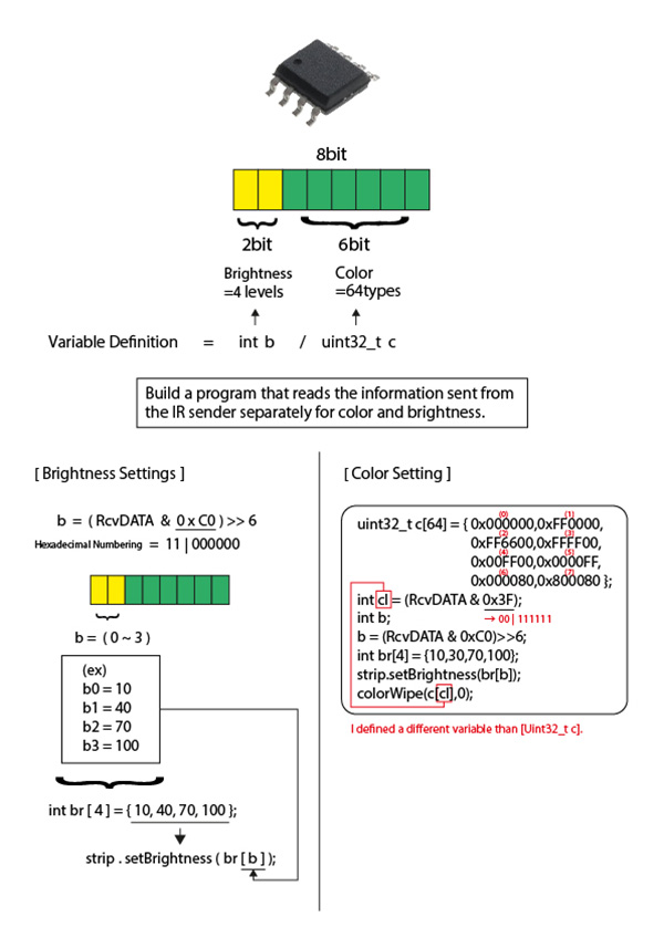
Changing the definition of color settings
I changed the definitions regarding “color” and “brightness” in the earring side of the program as follows. Out of the 8 bits of memory that ATtiny85 can handle, I assigned 2 bits to brightness and 6 bits to color to build the program. Neopixel color code can be set up to 64 colors.
Programming
//-------------------------------------------------------------------------------------------------------------------------
/*
 *  IrDA receive data print program
 *    IRreceive_print01.ino
 *      2020.5.28

 * Original Scketch
   ATtiny85 IR Remote Control Receiver
   David Johnson-Davies - www.technoblogy.com - 3rd April 2015
   ATtiny85 @ 1 MHz (internal oscillator; BOD disabled)
   CC BY 4.0
   Licensed under a Creative Commons Attribution 4.0 International license:
   http://creativecommons.org/licenses/by/4.0/
*/

//#include <SoftwareSerial.h> ソフトウェアシリアルの設定を追記
//SoftwareSerial mySerial(3, 4); RX(PB3:Pin2), TX(PB4:Pin3) ソフトウェアシリアルの設定を追記

// LED outputs
int LED = 1;   // LED indicator PB1(Pin6)

volatile int NextBit;
volatile unsigned long RecdData;
volatile int Rcvflag = 0; //受信フラグ
volatile int RcvDATA; //32bitのデータを収納する変数

char HEXprint[] = {'0','1','2','3','4','5','6','7','8','9','A','B','C','D','E','F'} ;

//ネオピクセル
#include <Adafruit_NeoPixel.h>
#ifdef __AVR__
#include <avr/power.h>
#endif

#define PIN 1

// Parameter 1 = number of pixels in strip
// Parameter 2 = Arduino pin number (most are valid)
// Parameter 3 = pixel type flags, add together as needed:
//   NEO_KHZ800  800 KHz bitstream (most NeoPixel products w/WS2812 LEDs)
//   NEO_KHZ400  400 KHz (classic 'v1' (not v2) FLORA pixels, WS2811 drivers)
//   NEO_GRB     Pixels are wired for GRB bitstream (most NeoPixel products)
//   NEO_RGB     Pixels are wired for RGB bitstream (v1 FLORA pixels, not v2)
//   NEO_RGBW    Pixels are wired for RGBW bitstream (NeoPixel RGBW products)
Adafruit_NeoPixel strip = Adafruit_NeoPixel(1, PIN, NEO_GRB + NEO_KHZ800);

// IMPORTANT: To reduce NeoPixel burnout risk, add 1000 uF capacitor across
// pixel power leads, add 300 - 500 Ohm resistor on first pixel's data input
// and minimize distance between Arduino and first pixel.  Avoid connecting
// on a live circuit...if you must, connect GND first.

// Setup **********************************************

void setup() {
  // Set up LEDs
  pinMode(LED, OUTPUT);

  // initialize Serial Port
  mySerial.begin(9600);
  delay(500);
  mySerial.println("Serial connect");

  // Set up Timer/Counter0 (assumes 8MHz clock)
  TCCR0A = 0;                 // No compare matches
  TCCR0B = 5<<CS00;           // Prescaler /64 でもプログラムでは"3"になっていた。これがInternal:1Mhzを8Mhzに変更するClock
  // Set up INT0 interrupt on PB2
  MCUCR = MCUCR | 2<<ISC00;   // Interrupt on falling edge
  GIMSK = GIMSK | 1<<INT0;    // Enable INT0
  NextBit = 32;               // Wait for AGC start pulse

  //ネオピクセル-------
  // This is for Trinket 5V 16MHz, you can remove these three lines if you are not using a Trinket
  #if defined (__AVR_ATtiny85__)
    if (F_CPU == 16000000) clock_prescale_set(clock_div_1);
  #endif
  // End of trinket special code

  strip.begin();
  strip.setBrightness(50);//最大255(でも155以上にはしないほうがいい)
  strip.show(); // Initialize all pixels to 'off'
  //ネオピクセル-------
}

void loop() { //Rcvfla=Receiveflagの略
  if (Rcvflag != 0){ //!=0・・・受信ができた
    Rcvflag = 0; //受信内容を理解したので消している
    char Pdata = (RcvDATA & 0xF0)>>4 ; // pickup upper 4 bits キーデータの最初の4bitだけ取り出している 受信したデータをシリアルコンソールに表示するコード※キーコードのみ(以下54行目〜
    mySerial.print(HEXprint[Pdata]);   // print in HEX
    Pdata = (RcvDATA & 0x0F);          // pickup lower 4 bits 残りの4bitを取り出している
    mySerial.println(HEXprint[Pdata]); // print in HEX
    //ネオピクセル------
    uint32_t c[64] = {0x000000,0xFF0000,//int c;を変更 理由:int=符号付24bitの整数 色を64色設定
                      0xFF6600,0xFFFF00,
                      0x00FF00,0x0000FF,
                      0x000080,0x800080};
    int cl = (RcvDATA & 0x3F);
    int b; //明るさを変えるための変数定義
    b = (RcvDATA & 0xC0)>>6;
    int br[4] = {10,30,70,100};
    strip.setBrightness(br[b]);
    colorWipe(c[cl],0);
    //ネオピクセル------
}
}

// *** Interrupt service routine - called on every falling edge of PB2 ***

ISR(INT0_vect) {
  int Time = TCNT0;
  int Overflow = TIFR & 1<<TOV0;
  // Keep looking for AGC pulse and gap
  if (NextBit == 32) {
    if ((Time >= 87) && (Time <= 114) && (Overflow == 0)) {
      RecdData = 0; NextBit = 0;
    } else if ((Time >= 80) && (Time <= 97) && (Overflow == 0)) ReceivedCode(1);
  // Data bit
  } else {
    if ((Time > 22) || (Overflow != 0)) NextBit = 32; // Invalid - restart
    else {
      if (Time > 13) RecdData = RecdData | ((unsigned long) 1<<NextBit);
      if (NextBit == 31) ReceivedCode(0);
      NextBit++;
    }
  }
  TCNT0 = 0;                  // Clear counter
  TIFR = TIFR | 1<<TOV0;      // Clear overflow
  GIFR = GIFR | 1<<INTF0;     // Clear INT0 flag
}

// Main Process after IrDA data received
void ReceivedCode(boolean Repeat) {
  // Check for correct remote control
  if ((RecdData & 0xFFFF) != 0xff00) return; // check the maker_code 0xFF
  // Read key pressed
  RcvDATA = RecdData>>16 & 0xFF;

  // Set DATA receivedflag for SerialPrint
  Rcvflag = 1;

}

//colorWipe(c,0);でエラーが起きたので追記
void colorWipe(uint32_t c, uint8_t wait) {
  for(uint16_t i=0; i<strip.numPixels(); i++) {
      strip.setPixelColor(i, c);
      strip.show();
      delay(wait);
  }
}
//colorWipe(c,0);でエラーが起きたので追記
⑦ Power Supply
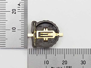
I have considered sharing the power to run the earring circuit from a button battery. I want to use only one button battery to keep the total amount of earrings under 10 grams. So I decided to use Lithium Battery CR1220 Golden Power.
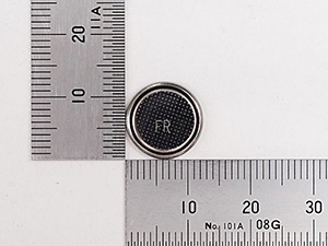
I also used dedicated battery holder.
| component | vender | cost(JPY) | quanitity | total | notes |
|---|---|---|---|---|---|
| Lithium battery CR1220 from Golden Power | Akitsukidenshi | ¥50 | 2 | ¥100 | shop link |
| Holder for Button Cell Substrate for CR1220 CH291-1220LF | Akitsukidenshi | ¥60 | 2 | ¥120 | shop link |
Breadboard Verification
I built the above button battery into the breadboard circuit and verified that it actually has no problems lighting up and how many hours of continuous lighting time it has.
breadboard photo
Video verification
However, later experiments after making the board revealed that the voltage was insufficient to display the Neopixel’s blue color with this button battery. So, I had to re-examine the button battery.
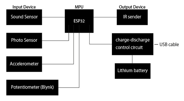
Obi clasp side
Function
- ESP32
- Infrared Transmission
- Potentiometer (for Blynk)
- Optical Sensor
- sound sensor
- accelerometer
- charge-discharge control circuit
- Program Writing
- debugging
↓
block diagram
Electronic components used
| component | vender | cost(JPY) | quanitity | total | notes |
|---|---|---|---|---|---|
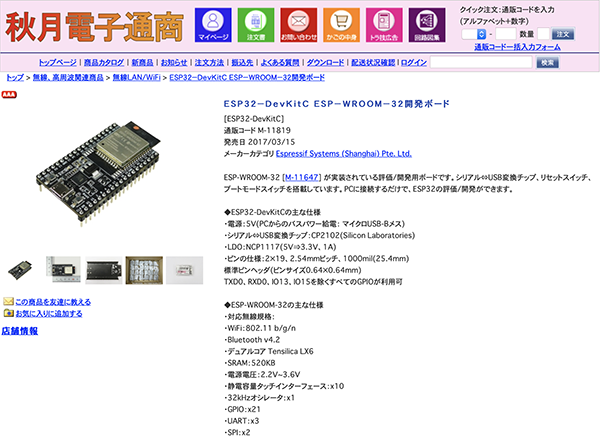
| ESP32-DevKitC ESP-WROOM-32 Development Board | Akitsukidenshi | ¥1480 | 1 | ¥1480 | shop link |
| Ks0027 keyestudio Digital IR Transmitter Module | keyestudio | US$2.50 | 1 | US$2.50 | shop link |
| Small volume 1KΩB | Akitsukidenshi | ¥40 | 1 | ¥40 | shop link |
| Photosensor_L-31ROPT1C | Akitsukidenshi | ¥200 | 1 | ¥200 | shop link |
| Sound sensor_WM-61A | Akitsukidenshi | ¥50 | 1 | ¥50 | shop link |
| Accelerometer_ADXL345 | Amazon | ¥720 | 1 | ¥720 | shop link |
| Rechargeable lithium battery(1000mAh) | MakerFocus(Amazon) | $22.99 | 1 | $22.99 | shop link |
| Lithium Ion Charging Module_TP4056 | Amazon | ¥680 | 1 | ¥680 | shop link |
| Carbon Resistor (Carbon Film Resistor) 1/6W33kΩ (100 pcs.) | Akitsukidenshi | ¥100 | 1 | ¥100 | shop link |
- 33kΩ・・・Since the sensitivity changes according to the Resistor value, we experimented with 10kΩ, 33kΩ, and 47kΩ, and the 33kΩ result was the best.
① ESP32
I chose the ESP32 as the MPU that changes the earring’s lighting pattern in response to ambient sound and brightness and sends this information. The reason for this is that I needed a larger memory to incorporate a program to control several input devices simultaneously.
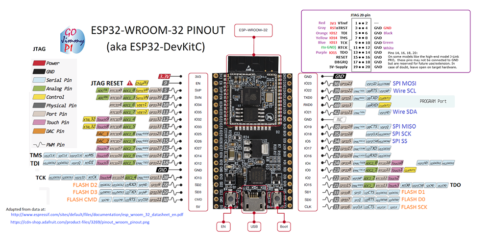
I have checked the ESP32 data sheet I use.
First, I checked the pin configuration of the ATtiny85. There are 38 pins in total. 1(3.3V), 2(GND), 14(GND) and 37(5V) are used for power supply. Connect a lithium battery to pin 37(5V). The following table shows the pins that can be used for the ADC to connect the Input and Output devices used in this project.
| constant | GPIO PIN |
|---|---|
| A0 | 36 |
| A3 | 39 |
| A4 | 32 |
| A5 | 33 |
| A6 | 34 |
| A7 | 35 |
| A10 | 4 |
| A11 | 0 |
| A12 | 2 |
| A13 | 15 |
| A14 | 13 |
| A15 | 12 |
| A16 | 14 |
| A17 | 27 |
| A18 | 25 |
| A19 | 26 |
A1 and A2 are not defined. It can be used with GPIO37 and 38 pins, but the parts are already wired for the Low-Noise Amplifier circuit described below. The GPIOs 0 and 2 may be used to control the write mode, and GPIOs 15 and 12 may be used for other functions.
I connected the signal lines of the device to 25 (IR sender), 32 (Potentiometer), 33() and 34() from the table above, respectively. I also connected the accelerometer SDA to pin 21 and SCL to pin 22 for the accelerometer. Assign 10(RX) and 8(TX) for debugging.
Writing a program to ESP32
When you use the Aruduino to write a program to the ESP32, you need to configure it as follows.
Setting details
- Board:”ESP32 Dev Module”
- Upload Speed:”115200”
- CPU Frequency:”240MHz(WiFi/BT)”
- Flash Frequency:”80Mhz”
- Flash Mode:”QIO”
- Flash Size:”4MB(32Mb)”
- Partition Scheme:”Defult 4MB with spiffs (1.2MB APP/1.5MB SPIFFS)”
- Core Debug Level:”None”
- PSRAM:”Disabled”
- Port:”/dev/cu.SLAB_USBtoUART”
- Programmer:”ArduinoISP”
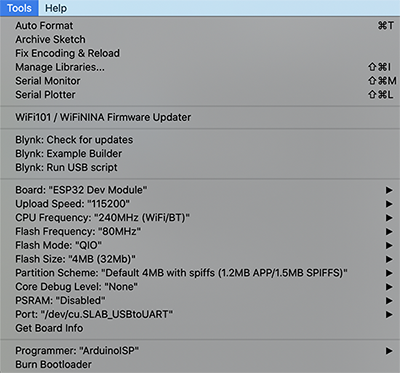
This allows the program to be written to the ESP32.
② IR Transmitter
I built the program for [RMT (Remote Control) Module experiment page for the ESP-WROOM-32 development board using Arduino core for the ESP32].
(1) RMT
The ESP-WROOM-32 has an RMT (Remote Control) Module, which is used to control the infrared remote control signals. Arduino core for the ESP32 has APIs for Arduino, but I used the ESP-IDF functions as they are.
(2) Data Settings
When sending data, set the data to be sent to the memory block (type rmt_item32_t) as much as needed. The definition of the [rmt_item32_t] type is as follows
typedef struct {
    union {
        struct {
            uint32_t duration0 :15;
            uint32_t level0 :1;
            uint32_t duration1 :15;
            uint32_t level1 :1;
        };
        uint32_t val;
    };
} rmt_item32_t;
level0 and level1 are member variables that control the output, which are set to 1 to turn on the output and 0 to turn off the output.
(3) Sending data
To send the configured data, call the following API.
esp_err_t rmt_write_items(rmt_channel_t channel, const rmt_item32_t *rmt_item, int item_num, bool wait_tx_done);
esp_err_t rmt_wait_tx_done(rmt_channel_t channel, TickType_t wait_time);
channel is the channel to be used. rmt_item is the top address of the memory block you set. item_num is the number of data to be sent (in pairs of ON/OFF).
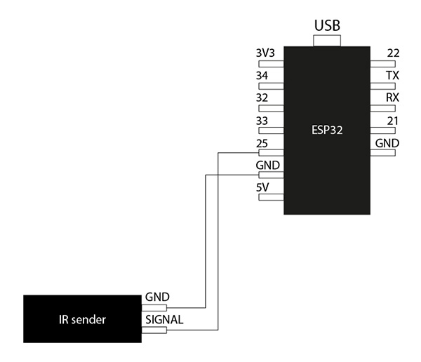
(4) Programming
The IR Transmitter is connected to pin 25. The device used in this project has a transistor built in from the start, so you don’t need to provide one.
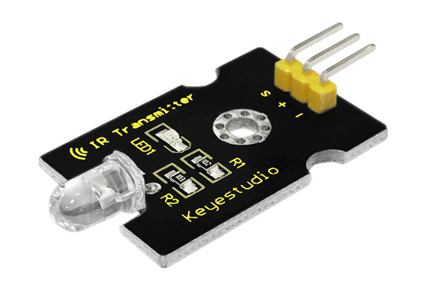
| Function | Numeric Value |
|---|---|
| Inframed emission distance | about 300mm |
| Inframed center frequency | 850nnm~940nm |
| Inframed emission angle | 20 degree |
breadboard diagram
breadboard photo
Programming
#include "driver/rmt.h"

const int rmtDataLength = 34;        // NEC format data length 34 bit
rmt_item32_t rmtData[rmtDataLength]; // data to send

const rmt_channel_t channel = RMT_CHANNEL_0;
const gpio_num_t irPin = GPIO_NUM_25;

const int leaderOnUs = 9000;
const int leaderOffUs = 4500;
const int dataOnUs = 560;
const int data1OffUs = 1690;
const int data0OffUs = 560;
const int stopbitOnUs = 560;
const int stopbitOffUs = 0x7fff;

/* send NEC format remote control data */
void sendData(uint16_t customCode, uint8_t dataCode) {
  /* leader code 1bit: ON 9000us, OFF 4500us */
  rmtData[0].duration0 = leaderOnUs;
  rmtData[0].level0 = 1;
  rmtData[0].duration1 = leaderOffUs;
  rmtData[0].level1 = 0;

  /*
   * custom code 16 bit
   * INPUT series: b15 b14 b13 b12 b11 b10 b09 b08 b07 b06 b05 b04 b03 b02 b01 b00
   * SEND  series: b08 b09 b10 b11 b12 b13 b14 b15 b00 b01 b02 b03 b04 b05 b06 b07
   */
  for (int i = 0; i < 2; i++) {
    for (int j = 0; j < 8; j++) {
      /*
       * 1: ON 560us + OFF 1690us
       * 0: ON 560us + OFF  560us
      */
      rmtData[8 * i + j + 1].duration0 = dataOnUs;
      rmtData[8 * i + j + 1].level0 = 1;
      if (customCode & (1 << ((1 - i) * 8 + j))) {
        rmtData[8 * i + j + 1].duration1 = data1OffUs;
      } else {
        rmtData[8 * i + j + 1].duration1 = data0OffUs;
      }
      rmtData[8 * i + j + 1].level1 = 0;
    }
  }

  /*
   * data code 8bit
   * INPUT series: b7 b6 b5 b4 b3 b2 b1 b0
   * SEND  series: b0 b1 b2 b3 b4 b5 b6 b7 ~b0 ~b1 ~b2 ~b3 ~b4 ~b5 ~b6 ~b7
   */
  for (int i = 0; i < 8; i++) {
    rmtData[i + 17].duration0 = dataOnUs;
    rmtData[i + 25].duration0 = dataOnUs;
    rmtData[i + 17].level0 = 1;
    rmtData[i + 25].level0 = 1;
    if (dataCode & (1 << i)) {
      rmtData[i + 17].duration1 = data1OffUs;
      rmtData[i + 25].duration1 = data0OffUs;
    } else {
      rmtData[i + 17].duration1 = data0OffUs;
      rmtData[i + 25].duration1 = data1OffUs;
    }
    rmtData[i + 17].level1 = 0;
    rmtData[i + 25].level1 = 0;
  }

  /* stop bit 1bit: ON 560 */
  rmtData[33].duration0 = stopbitOnUs;
  rmtData[33].level0 = 1;
  rmtData[33].duration1 = stopbitOffUs;
  rmtData[33].level1 = 0;

  rmt_write_items(channel, rmtData, rmtDataLength, true);
}

void setup() {
  // put your setup code here, to run once:
  rmt_config_t rmtConfig;

  rmtConfig.rmt_mode = RMT_MODE_TX;  // transmit mode
  rmtConfig.channel = channel;  // channel to use 0 - 7
  rmtConfig.clk_div = 80;  // clock divider 1 - 255. source clock is 80MHz -> 80MHz/80 = 1MHz -> 1 tick = 1 us
  rmtConfig.gpio_num = irPin; // pin to use
  rmtConfig.mem_block_num = 1; // memory block size

  rmtConfig.tx_config.loop_en = 0; // no loop
  rmtConfig.tx_config.carrier_freq_hz = 38000;  // IR remote controller uses 38kHz carrier frequency
  rmtConfig.tx_config.carrier_duty_percent = 33; // duty
  rmtConfig.tx_config.carrier_level =  RMT_CARRIER_LEVEL_HIGH; // carrier level
  rmtConfig.tx_config.carrier_en = 1;  // carrier enable
  rmtConfig.tx_config.idle_level =  RMT_IDLE_LEVEL_LOW ; // signal level at idle
  rmtConfig.tx_config.idle_output_en = 1;  // output if idle

  rmt_config(&rmtConfig);
  rmt_driver_install(rmtConfig.channel, 0, 0);
}

void loop() {
  // put your main code here, to run repeatedly:
  //受信機側の変数を入力する
  sendData(0x00FF, 0x16);//0
  delay(1000);
  sendData(0x00FF, 0x0C);//1
  delay(1000);
}
This program repeats the Neopixel blink every 1000 m/t. (If there is no [delay(1000)], it repeats every c108 m/t. (If there is no [delay(1000)], the program will blink every c108m/t.) We have confirmed that the infrared transmission program works well.
③ Input Devices
The next step is to incorporate a potentiometer, a phototransistor, and a sound sensor to build the program. I have configured each of these input devices as follows.
void setup(){
  ~~~
  pinMode(PotPin,INPUT);
  pinMode(AmbPin,INPUT);
  pinMode(SndPin,INPUT);
}
These analog conversion values (0~4096) and their corresponding colors were assigned using a hexadecimal variable [#define] to define seven colors as follows.
#define k0 0x16
#define k1 0x0C
#define k2 0x18
#define k3 0x5E
#define k4 0x08
#define k5 0x1C
#define k6 0x5A
#define k7 0x42
And these seven colors and analog conversion values were set to correspond as follows.
| analog conversion value | Color |
|---|---|
| 0 ~ 500 | k0 |
| 500 ~ 1000 | k1 |
| 1000 ~ 1500 | k2 |
| 1500 ~ 2000 | k3 |
| 2000 ~ 2500 | k4 |
| 2500 ~ 3000 | k5 |
| 3000 ~ 3500 | k6 |
| 3500 ~ 4000 | k7 |
To load these settings, we defined the following variables.
void loop() {
  // put your main code here, to run repeatedly:
  int analogdata1 = analogRead(PotPin);
  int analogdata2 = analogRead(AmbPin);
  int analogdata3 = analogRead(SndPin);
 ~~~
}
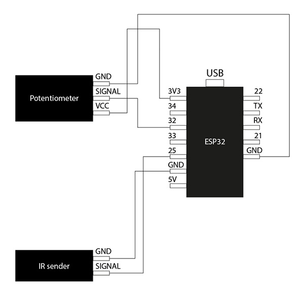
(1) Potentiometer
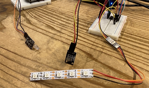
First, I added a potentiometer to the circuit and created a program to change the color of the neopixels and a breadboard circuit.
breadboard diagram
breadboard photo
Programming
#include "driver/rmt.h"

//16進数の変数を#defineを使って代入
#define k0 0x16
#define k1 0x0C
#define k2 0x18
#define k3 0x5E
#define k4 0x08
#define k5 0x1C
#define k6 0x5A
#define k7 0x42

const int rmtDataLength = 34;        // NEC format data length 34 bit
rmt_item32_t rmtData[rmtDataLength]; // data to send

const rmt_channel_t channel = RMT_CHANNEL_0;
const gpio_num_t irPin = GPIO_NUM_25;

//ポテンショメータ(Pot)センサーを定義する
const gpio_num_t PotPin = GPIO_NUM_32;

//読み込むデータの定義
uint8_t txd;//8bitの符号なしのデータ

const int leaderOnUs = 9000;
const int leaderOffUs = 4500;
const int dataOnUs = 560;
const int data1OffUs = 1690;
const int data0OffUs = 560;
const int stopbitOnUs = 560;
const int stopbitOffUs = 0x7fff;

/* send NEC format remote control data */
void sendData(uint16_t customCode, uint8_t dataCode) {
  /* leader code 1bit: ON 9000us, OFF 4500us */
  rmtData[0].duration0 = leaderOnUs;
  rmtData[0].level0 = 1;
  rmtData[0].duration1 = leaderOffUs;
  rmtData[0].level1 = 0;

  /*
   * custom code 16 bit
   * INPUT series: b15 b14 b13 b12 b11 b10 b09 b08 b07 b06 b05 b04 b03 b02 b01 b00
   * SEND  series: b08 b09 b10 b11 b12 b13 b14 b15 b00 b01 b02 b03 b04 b05 b06 b07
   */
  for (int i = 0; i < 2; i++) {
    for (int j = 0; j < 8; j++) {
      /*
       * 1: ON 560us + OFF 1690us
       * 0: ON 560us + OFF  560us
      */
      rmtData[8 * i + j + 1].duration0 = dataOnUs;
      rmtData[8 * i + j + 1].level0 = 1;
      if (customCode & (1 << ((1 - i) * 8 + j))) {
        rmtData[8 * i + j + 1].duration1 = data1OffUs;
      } else {
        rmtData[8 * i + j + 1].duration1 = data0OffUs;
      }
      rmtData[8 * i + j + 1].level1 = 0;
    }
  }

  /*
   * data code 8bit
   * INPUT series: b7 b6 b5 b4 b3 b2 b1 b0
   * SEND  series: b0 b1 b2 b3 b4 b5 b6 b7 ~b0 ~b1 ~b2 ~b3 ~b4 ~b5 ~b6 ~b7
   */
  for (int i = 0; i < 8; i++) {
    rmtData[i + 17].duration0 = dataOnUs;
    rmtData[i + 25].duration0 = dataOnUs;
    rmtData[i + 17].level0 = 1;
    rmtData[i + 25].level0 = 1;
    if (dataCode & (1 << i)) {
      rmtData[i + 17].duration1 = data1OffUs;
      rmtData[i + 25].duration1 = data0OffUs;
    } else {
      rmtData[i + 17].duration1 = data0OffUs;
      rmtData[i + 25].duration1 = data1OffUs;
    }
    rmtData[i + 17].level1 = 0;
    rmtData[i + 25].level1 = 0;
  }

  /* stop bit 1bit: ON 560 */
  rmtData[33].duration0 = stopbitOnUs;
  rmtData[33].level0 = 1;
  rmtData[33].duration1 = stopbitOffUs;
  rmtData[33].level1 = 0;

  rmt_write_items(channel, rmtData, rmtDataLength, true);
}

void setup() {
  // put your setup code here, to run once:
  rmt_config_t rmtConfig;

  rmtConfig.rmt_mode = RMT_MODE_TX;  // transmit mode
  rmtConfig.channel = channel;  // channel to use 0 - 7
  rmtConfig.clk_div = 80;  // clock divider 1 - 255. source clock is 80MHz -> 80MHz/80 = 1MHz -> 1 tick = 1 us
  rmtConfig.gpio_num = irPin; // pin to use
  rmtConfig.mem_block_num = 1; // memory block size

  rmtConfig.tx_config.loop_en = 0; // no loop
  rmtConfig.tx_config.carrier_freq_hz = 38000;  // IR remote controller uses 38kHz carrier frequency
  rmtConfig.tx_config.carrier_duty_percent = 33; // duty
  rmtConfig.tx_config.carrier_level =  RMT_CARRIER_LEVEL_HIGH; // carrier level
  rmtConfig.tx_config.carrier_en = 1;  // carrier enable
  rmtConfig.tx_config.idle_level =  RMT_IDLE_LEVEL_LOW ; // signal level at idle
  rmtConfig.tx_config.idle_output_en = 1;  // output if idle

  rmt_config(&rmtConfig);
  rmt_driver_install(rmtConfig.channel, 0, 0);
//ピンモード設定をする
  pinMode(PotPin,INPUT);
}

void loop() {
  // put your main code here, to run repeatedly:
  int analogdata1 = analogRead(PotPin);
  //ポテンショメータで制御するプログラム
  if(analogdata1<500){
    txd = k0;
  }
  else if(analogdata1<1000){
    txd = k1;
  }
  else if(analogdata1<1500){
    txd = k2;
  }
  else if(analogdata1<2000){
    txd = k3;
  }
  else if(analogdata1<2500){
    txd = k4;
  }
  else if(analogdata1<3000){
    txd = k5;
  }
  else if(analogdata1<3500){
    txd = k6;
  }
  else{
    txd = k7;
  }
  sendData(0x00FF,txd);
}
I made sure to turn the potentiometer and it changes color.
(2) phototransistor
The next step was to add a phototransistor to the circuit and create a program and breadboard circuit to change the color of the neopixels.
breadboard diagram
breadboard photo
Programming
#include "driver/rmt.h"

//16進数の変数を#defineを使って代入
#define k0 0x16
#define k1 0x0C
#define k2 0x18
#define k3 0x5E
#define k4 0x08
#define k5 0x1C
#define k6 0x5A
#define k7 0x42

const int rmtDataLength = 34;        // NEC format data length 34 bit
rmt_item32_t rmtData[rmtDataLength]; // data to send

const rmt_channel_t channel = RMT_CHANNEL_0;
const gpio_num_t irPin = GPIO_NUM_25;

//光(Amb)センサーを定義する
const gpio_num_t AmbPin = GPIO_NUM_33;

//読み込むデータの定義
uint8_t txd;//8bitの符号なしのデータ

const int leaderOnUs = 9000;
const int leaderOffUs = 4500;
const int dataOnUs = 560;
const int data1OffUs = 1690;
const int data0OffUs = 560;
const int stopbitOnUs = 560;
const int stopbitOffUs = 0x7fff;

/* send NEC format remote control data */
void sendData(uint16_t customCode, uint8_t dataCode) {
  /* leader code 1bit: ON 9000us, OFF 4500us */
  rmtData[0].duration0 = leaderOnUs;
  rmtData[0].level0 = 1;
  rmtData[0].duration1 = leaderOffUs;
  rmtData[0].level1 = 0;

  /*
   * custom code 16 bit
   * INPUT series: b15 b14 b13 b12 b11 b10 b09 b08 b07 b06 b05 b04 b03 b02 b01 b00
   * SEND  series: b08 b09 b10 b11 b12 b13 b14 b15 b00 b01 b02 b03 b04 b05 b06 b07
   */
  for (int i = 0; i < 2; i++) {
    for (int j = 0; j < 8; j++) {
      /*
       * 1: ON 560us + OFF 1690us
       * 0: ON 560us + OFF  560us
      */
      rmtData[8 * i + j + 1].duration0 = dataOnUs;
      rmtData[8 * i + j + 1].level0 = 1;
      if (customCode & (1 << ((1 - i) * 8 + j))) {
        rmtData[8 * i + j + 1].duration1 = data1OffUs;
      } else {
        rmtData[8 * i + j + 1].duration1 = data0OffUs;
      }
      rmtData[8 * i + j + 1].level1 = 0;
    }
  }

  /*
   * data code 8bit
   * INPUT series: b7 b6 b5 b4 b3 b2 b1 b0
   * SEND  series: b0 b1 b2 b3 b4 b5 b6 b7 ~b0 ~b1 ~b2 ~b3 ~b4 ~b5 ~b6 ~b7
   */
  for (int i = 0; i < 8; i++) {
    rmtData[i + 17].duration0 = dataOnUs;
    rmtData[i + 25].duration0 = dataOnUs;
    rmtData[i + 17].level0 = 1;
    rmtData[i + 25].level0 = 1;
    if (dataCode & (1 << i)) {
      rmtData[i + 17].duration1 = data1OffUs;
      rmtData[i + 25].duration1 = data0OffUs;
    } else {
      rmtData[i + 17].duration1 = data0OffUs;
      rmtData[i + 25].duration1 = data1OffUs;
    }
    rmtData[i + 17].level1 = 0;
    rmtData[i + 25].level1 = 0;
  }

  /* stop bit 1bit: ON 560 */
  rmtData[33].duration0 = stopbitOnUs;
  rmtData[33].level0 = 1;
  rmtData[33].duration1 = stopbitOffUs;
  rmtData[33].level1 = 0;

  rmt_write_items(channel, rmtData, rmtDataLength, true);
}

void setup() {
  // put your setup code here, to run once:
  rmt_config_t rmtConfig;

  rmtConfig.rmt_mode = RMT_MODE_TX;  // transmit mode
  rmtConfig.channel = channel;  // channel to use 0 - 7
  rmtConfig.clk_div = 80;  // clock divider 1 - 255. source clock is 80MHz -> 80MHz/80 = 1MHz -> 1 tick = 1 us
  rmtConfig.gpio_num = irPin; // pin to use
  rmtConfig.mem_block_num = 1; // memory block size

  rmtConfig.tx_config.loop_en = 0; // no loop
  rmtConfig.tx_config.carrier_freq_hz = 38000;  // IR remote controller uses 38kHz carrier frequency
  rmtConfig.tx_config.carrier_duty_percent = 33; // duty
  rmtConfig.tx_config.carrier_level =  RMT_CARRIER_LEVEL_HIGH; // carrier level
  rmtConfig.tx_config.carrier_en = 1;  // carrier enable
  rmtConfig.tx_config.idle_level =  RMT_IDLE_LEVEL_LOW ; // signal level at idle
  rmtConfig.tx_config.idle_output_en = 1;  // output if idle

  rmt_config(&rmtConfig);
  rmt_driver_install(rmtConfig.channel, 0, 0);
//ピンモード設定をする
  pinMode(AmbPin,INPUT);
}

void loop() {
  // put your main code here, to run repeatedly:
  int analogdata2 = analogRead(AmbPin);
  //フォトトランジスタで制御するプログラム
  if(analogdata2<500){
    txd = k0;
  }
  else if(analogdata2<1000){
    txd = k1;
  }
  else if(analogdata2<1500){
    txd = k2;
  }
  else if(analogdata2<2000){
    txd = k3;
  }
  else if(analogdata2<2500){
    txd = k4;
  }
  else if(analogdata2<3000){
    txd = k5;
  }
  else if(analogdata2<3500){
    txd = k6;
  }
  else{
    txd = k7;
  }
  sendData(0x00FF,txd);
}
The sensitivity of a phototransistor depends on its Resistor value. The higher the Resistor value, the greater the range of light that can be detected in the dark, and the lower the Resistor value, the greater the range of light that can be detected in the brighter areas.
Resistor Color Code Calculator
The first one I tried was [10kΩ]. When I shone the light on my iPhone, the color changed.
The next thing I tried was [33kΩ]. When I covered the phototransistor with my hand, I saw the color change.
The last thing I tried was [47kΩ]. I saw the color change when I covered the phototransistor by hand, but I found that the color didn’t change until it was quite dark.
After reviewing these differences, I decided that the sensitivity was most appropriate when I incorporated the [33kΩ].
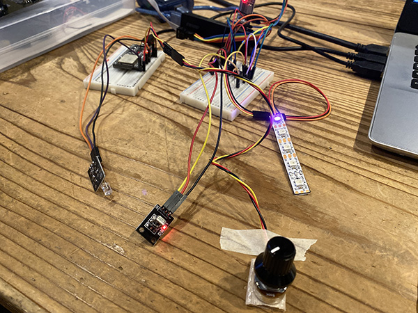
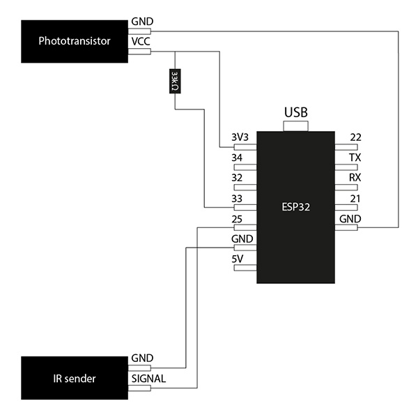
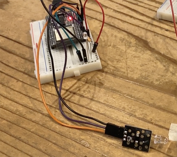
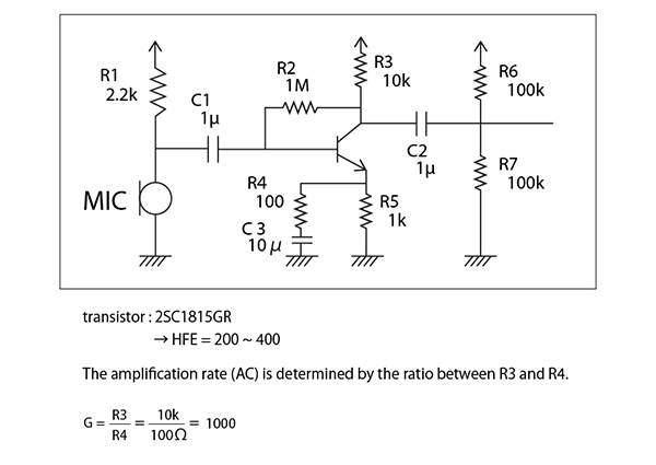
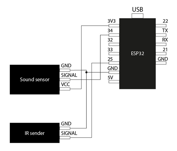
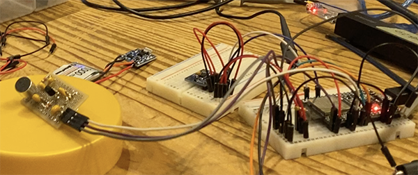
(3) sound sensor
The next step was to add a sound sensor to the circuit and create a program and breadboard circuit to change the color of the Neopixels.
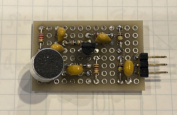
schematic
breadboard diagram
breadboard photo
Programming
#include "driver/rmt.h"

//16進数の変数を#defineを使って代入
#define k0 0x16
#define k1 0x0C
#define k2 0x18
#define k3 0x5E
#define k4 0x08
#define k5 0x1C
#define k6 0x5A
#define k7 0x42

const int rmtDataLength = 34;        // NEC format data length 34 bit
rmt_item32_t rmtData[rmtDataLength]; // data to send

const rmt_channel_t channel = RMT_CHANNEL_0;
const gpio_num_t irPin = GPIO_NUM_25;

//音(Snd)センサーを定義する
const gpio_num_t SndPin = GPIO_NUM_34;

//読み込むデータの定義
uint8_t txd;//8bitの符号なしのデータ

const int leaderOnUs = 9000;
const int leaderOffUs = 4500;
const int dataOnUs = 560;
const int data1OffUs = 1690;
const int data0OffUs = 560;
const int stopbitOnUs = 560;
const int stopbitOffUs = 0x7fff;

/* send NEC format remote control data */
void sendData(uint16_t customCode, uint8_t dataCode) {
  /* leader code 1bit: ON 9000us, OFF 4500us */
  rmtData[0].duration0 = leaderOnUs;
  rmtData[0].level0 = 1;
  rmtData[0].duration1 = leaderOffUs;
  rmtData[0].level1 = 0;

  /*
   * custom code 16 bit
   * INPUT series: b15 b14 b13 b12 b11 b10 b09 b08 b07 b06 b05 b04 b03 b02 b01 b00
   * SEND  series: b08 b09 b10 b11 b12 b13 b14 b15 b00 b01 b02 b03 b04 b05 b06 b07
   */
  for (int i = 0; i < 2; i++) {
    for (int j = 0; j < 8; j++) {
      /*
       * 1: ON 560us + OFF 1690us
       * 0: ON 560us + OFF  560us
      */
      rmtData[8 * i + j + 1].duration0 = dataOnUs;
      rmtData[8 * i + j + 1].level0 = 1;
      if (customCode & (1 << ((1 - i) * 8 + j))) {
        rmtData[8 * i + j + 1].duration1 = data1OffUs;
      } else {
        rmtData[8 * i + j + 1].duration1 = data0OffUs;
      }
      rmtData[8 * i + j + 1].level1 = 0;
    }
  }

  /*
   * data code 8bit
   * INPUT series: b7 b6 b5 b4 b3 b2 b1 b0
   * SEND  series: b0 b1 b2 b3 b4 b5 b6 b7 ~b0 ~b1 ~b2 ~b3 ~b4 ~b5 ~b6 ~b7
   */
  for (int i = 0; i < 8; i++) {
    rmtData[i + 17].duration0 = dataOnUs;
    rmtData[i + 25].duration0 = dataOnUs;
    rmtData[i + 17].level0 = 1;
    rmtData[i + 25].level0 = 1;
    if (dataCode & (1 << i)) {
      rmtData[i + 17].duration1 = data1OffUs;
      rmtData[i + 25].duration1 = data0OffUs;
    } else {
      rmtData[i + 17].duration1 = data0OffUs;
      rmtData[i + 25].duration1 = data1OffUs;
    }
    rmtData[i + 17].level1 = 0;
    rmtData[i + 25].level1 = 0;
  }

  /* stop bit 1bit: ON 560 */
  rmtData[33].duration0 = stopbitOnUs;
  rmtData[33].level0 = 1;
  rmtData[33].duration1 = stopbitOffUs;
  rmtData[33].level1 = 0;

  rmt_write_items(channel, rmtData, rmtDataLength, true);
}

void setup() {
  // put your setup code here, to run once:
  rmt_config_t rmtConfig;

  rmtConfig.rmt_mode = RMT_MODE_TX;  // transmit mode
  rmtConfig.channel = channel;  // channel to use 0 - 7
  rmtConfig.clk_div = 80;  // clock divider 1 - 255. source clock is 80MHz -> 80MHz/80 = 1MHz -> 1 tick = 1 us
  rmtConfig.gpio_num = irPin; // pin to use
  rmtConfig.mem_block_num = 1; // memory block size

  rmtConfig.tx_config.loop_en = 0; // no loop
  rmtConfig.tx_config.carrier_freq_hz = 38000;  // IR remote controller uses 38kHz carrier frequency
  rmtConfig.tx_config.carrier_duty_percent = 33; // duty
  rmtConfig.tx_config.carrier_level =  RMT_CARRIER_LEVEL_HIGH; // carrier level
  rmtConfig.tx_config.carrier_en = 1;  // carrier enable
  rmtConfig.tx_config.idle_level =  RMT_IDLE_LEVEL_LOW ; // signal level at idle
  rmtConfig.tx_config.idle_output_en = 1;  // output if idle

  rmt_config(&rmtConfig);
  rmt_driver_install(rmtConfig.channel, 0, 0);
//ピンモード設定をする
  pinMode(SndPin,INPUT);
}

void loop() {
  // put your main code here, to run repeatedly:
  int analogdata3 = analogRead(SndPin);
  //サウンドセンサーで制御するプログラム
  if(analogdata3<500){
    txd = k0;
  }
  else if(analogdata3<1000){
    txd = k1;
  }
  else if(analogdata3<1500){
    txd = k2;
  }
  else if(analogdata3<2000){
    txd = k3;
  }
  else if(analogdata3<2500){
    txd = k4;
  }
  else if(analogdata3<3000){
    txd = k5;
  }
  else if(analogdata3<3500){
    txd = k6;
  }
  else{
    txd = k7;
  }
  sendData(0x00FF,txd);
}
I used an oscilloscope to confirm that the voltage was varying around the roughly 2000 position in the 0 to 4096 conversion. However, I found it difficult to find a way to make it glow with a fixed color for the sound because I didn’t know where in the sound I was sampling in terms of pitch and loudness of the sound. So I felt that it would be interesting to be able to represent the sampling of an indeterminate sound with an image like a “shimmer”.
Also, if the sound was short in length, the Neopixel did not convert the voltage well and the Neopixel would not glow.
④ Accelerometer ADXL345
I decided to use the accelerometer, the ADXL345, as a controller to change the lighting pattern.
Example 1) Single tap - the color changes in sequence Example 2) Double-tapping to change the color pattern
The ADXL345 is very well suited for mobile device applications. It can measure the static acceleration of gravity, such as in tilt sensing applications, as well as the dynamic acceleration of motion, shock or vibration. Its high resolution (4mg/LSB) allows for measurement of tilt changes of less than 1.0°.
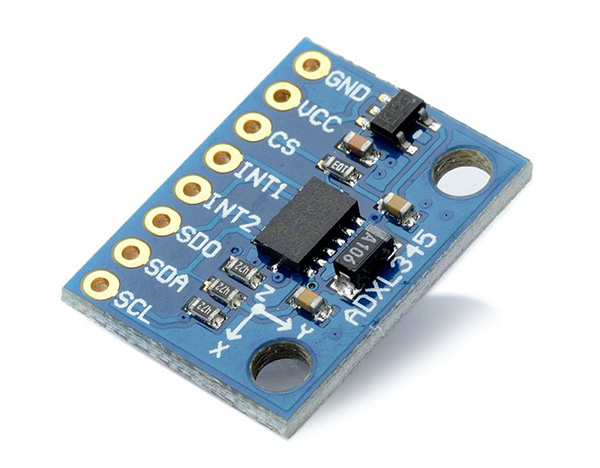
schematic
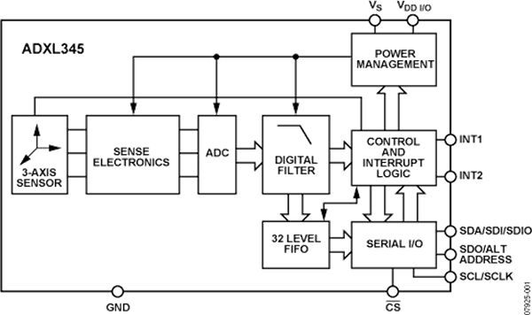
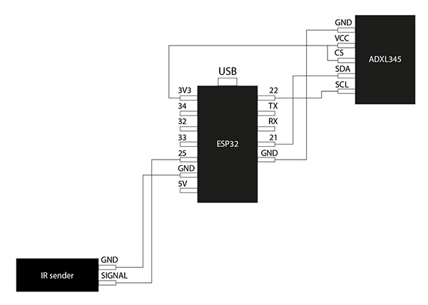
This time, the pins used on the ADXL345 side are GND, VCC & CS (I2C mode … High to I2C), SDA (DataLine) and SCL (ClockLine).
I looked up the pins for the ESP32 SDA and SCL from the following site.
The SDA connects to IO21 and the SCL connects to IO22.
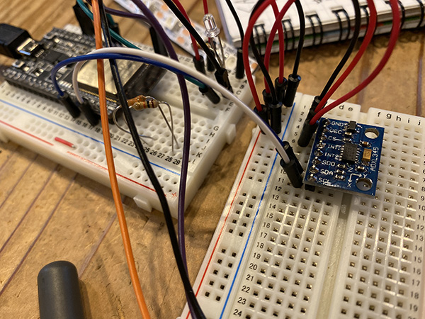
breadboard diagram
breadboard photo
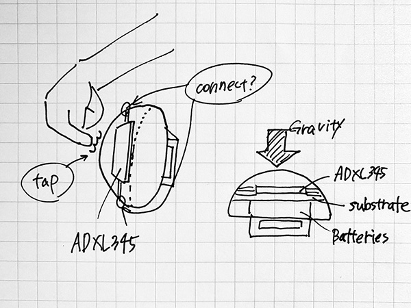
Before programming, the direction in which the ADXL345 is installed changes the direction in which it detects gravity, so I designed an overall view of the obi clamping system. I also thought about where to install the ADXL345, as we would need to adjust the sensitivity.
Installing the ADXL345 library
I installed the ADXL345 library from the link below.
Accelerometer_ADXL345-1.0.0.zip
The following program is a sample sketch from the library. I checked the program to see if it works in ESP32. [File] → [Example Sketch] → [Adxl345] → [ADXL345_Example].
Line 60) adxl.readAccel → adxl.readXYZ → Compile
Programming
#include <Wire.h>
#include <ADXL345.h>

ADXL345 adxl;

void setup(){
  Serial.begin(9600);
  adxl.powerOn();

  //set activity/ inactivity thresholds (0-255)
  adxl.setActivityThreshold(75); //62.5mg per increment
  adxl.setInactivityThreshold(75); //62.5mg per increment
  adxl.setTimeInactivity(10); // how many seconds of no activity is inactive?

  //look of activity movement on this axes - 1 == on; 0 == off
  adxl.setActivityX(1);
  adxl.setActivityY(1);
  adxl.setActivityZ(1);

  //look of inactivity movement on this axes - 1 == on; 0 == off
  adxl.setInactivityX(1);
  adxl.setInactivityY(1);
  adxl.setInactivityZ(1);

  //look of tap movement on this axes - 1 == on; 0 == off
  adxl.setTapDetectionOnX(0);
  adxl.setTapDetectionOnY(0);
  adxl.setTapDetectionOnZ(1);

  //set values for what is a tap, and what is a double tap (0-255)
  adxl.setTapThreshold(50); //62.5mg per increment
  adxl.setTapDuration(15); //625μs per increment
  adxl.setDoubleTapLatency(80); //1.25ms per increment
  adxl.setDoubleTapWindow(200); //1.25ms per increment

  //set values for what is considered freefall (0-255)
  adxl.setFreeFallThreshold(7); //(5 - 9) recommended - 62.5mg per increment
  adxl.setFreeFallDuration(45); //(20 - 70) recommended - 5ms per increment

  //setting all interupts to take place on int pin 1
  //I had issues with int pin 2, was unable to reset it
  adxl.setInterruptMapping( ADXL345_INT_SINGLE_TAP_BIT,   ADXL345_INT1_PIN );
  adxl.setInterruptMapping( ADXL345_INT_DOUBLE_TAP_BIT,   ADXL345_INT1_PIN );
  adxl.setInterruptMapping( ADXL345_INT_FREE_FALL_BIT,    ADXL345_INT1_PIN );
  adxl.setInterruptMapping( ADXL345_INT_ACTIVITY_BIT,     ADXL345_INT1_PIN );
  adxl.setInterruptMapping( ADXL345_INT_INACTIVITY_BIT,   ADXL345_INT1_PIN );

  //register interupt actions - 1 == on; 0 == off
  adxl.setInterrupt( ADXL345_INT_SINGLE_TAP_BIT, 1);
  adxl.setInterrupt( ADXL345_INT_DOUBLE_TAP_BIT, 1);
  adxl.setInterrupt( ADXL345_INT_FREE_FALL_BIT,  1);
  adxl.setInterrupt( ADXL345_INT_ACTIVITY_BIT,   1);
  adxl.setInterrupt( ADXL345_INT_INACTIVITY_BIT, 1);
}

void loop(){

  //Boring accelerometer stuff
  int x,y,z;
  adxl.readAccel(&x, &y, &z); //read the accelerometer values and store them in variables  x,y,z

  // Output x,y,z values - Commented out
  //Serial.print(x);
  //Serial.print(y);
  //Serial.println(z);


  //Fun Stuff!
  //read interrupts source and look for triggerd actions

  //getInterruptSource clears all triggered actions after returning value
  //so do not call again until you need to recheck for triggered actions
   byte interrupts = adxl.getInterruptSource();

  // freefall
  if(adxl.triggered(interrupts, ADXL345_FREE_FALL)){
    Serial.println("Free-fall detected.");           //自由落下を検出しました。
    //add code here to do when freefall is sensed
  }

  //inactivity
  if(adxl.triggered(interrupts, ADXL345_INACTIVITY)){
    Serial.println("No motion detected.");          //動きを検出しなかった。
     //add code here to do when inactivity is sensed
  }

  //activity
  if(adxl.triggered(interrupts, ADXL345_ACTIVITY)){
    Serial.println("Motion detected.");                 //動きを検出しました。
     //add code here to do when activity is sensed
  }

  //double tap
  if(adxl.triggered(interrupts, ADXL345_DOUBLE_TAP)){
    Serial.println("Double tap detected.");           //ダブルタップを検出しました。
     //add code here to do when a 2X tap is sensed
  }

  //tap
  if(adxl.triggered(interrupts, ADXL345_SINGLE_TAP)){
    Serial.println("Single tap detected.");            //シングルタップを検出しました。
     //add code here to do when a tap is sensed
  }
}
When I checked the operation with the above program, I saw [Single Tap] and [Motion Detected] when I double tapped. I need to build a program that ignores single taps when double taps are detected. So, I added the following code in [Single Tap].
if(adxl.triggered(interrupts, ADXL345_SINGLE_TAP) && !adxl.triggered(interrupts, ADXL345_DOUBLE_TAP)){
    Serial.println("Single tap detected.");
  }
}
また、[Motion Detected]が出るということはADXL345の感度が高すぎるので、これを低く設定する必要があります。 なので、15~18行目を下記のように修正しました。
Also, if [Motion Detected] appears, the sensitivity of the ADXL345 is too high, so it needs to be set lower. Therefore, lines 15 to 18 have been modified as follows.
 //look of activity movement on this axes - 1 == on; 0 == off
  adxl.setActivityX(0);
  adxl.setActivityY(0);
  adxl.setActivityZ(0);//上から叩かれた時のMotionを検出しなくなる
Programming
#include <Wire.h>
#include <ADXL345.h>

ADXL345 adxl;

void setup(){//どのくらい動いたら検出するのか、その値を設定している
  Serial.begin(9600);//検出した結果をシリアルモニターに表示する
  adxl.powerOn();

  //set activity/ inactivity thresholds (0-255)余分なMotionDitectedを検出しないようにした
  adxl.setActivityThreshold(150); //62.5mg per increment
  adxl.setInactivityThreshold(75); //62.5mg per increment
  adxl.setTimeInactivity(10); // how many seconds of no activity is inactive?

  //look of activity movement on this axes - 1 == on; 0 == off
  adxl.setActivityX(0);
  adxl.setActivityY(0);
  adxl.setActivityZ(0);//上から叩かれた時のMotionを検出しなくなる

  //look of inactivity movement on this axes - 1 == on; 0 == off
  adxl.setInactivityX(1);
  adxl.setInactivityY(1);
  adxl.setInactivityZ(1);

  //look of tap movement on this axes - 1 == on; 0 == off
  adxl.setTapDetectionOnX(0);
  adxl.setTapDetectionOnY(0);
  adxl.setTapDetectionOnZ(1);

  //set values for what is a tap, and what is a double tap (0-255)//シングルタップの感度を下げた
  adxl.setTapThreshold(80); //62.5mg per increment
  adxl.setTapDuration(15); //625μs per increment
  adxl.setDoubleTapLatency(80); //1.25ms per increment
  adxl.setDoubleTapWindow(200); //1.25ms per increment

  //set values for what is considered freefall (0-255)
  adxl.setFreeFallThreshold(7); //(5 - 9) recommended - 62.5mg per increment
  adxl.setFreeFallDuration(45); //(20 - 70) recommended - 5ms per increment

  //setting all interupts to take place on int pin 1
  //I had issues with int pin 2, was unable to reset it
  adxl.setInterruptMapping( ADXL345_INT_SINGLE_TAP_BIT,   ADXL345_INT1_PIN );
  adxl.setInterruptMapping( ADXL345_INT_DOUBLE_TAP_BIT,   ADXL345_INT1_PIN );
  adxl.setInterruptMapping( ADXL345_INT_FREE_FALL_BIT,    ADXL345_INT1_PIN );
  adxl.setInterruptMapping( ADXL345_INT_ACTIVITY_BIT,     ADXL345_INT1_PIN );
  adxl.setInterruptMapping( ADXL345_INT_INACTIVITY_BIT,   ADXL345_INT1_PIN );

  //register interupt actions - 1 == on; 0 == off
  adxl.setInterrupt( ADXL345_INT_SINGLE_TAP_BIT, 1);
  adxl.setInterrupt( ADXL345_INT_DOUBLE_TAP_BIT, 1);
  adxl.setInterrupt( ADXL345_INT_FREE_FALL_BIT,  1);
  adxl.setInterrupt( ADXL345_INT_ACTIVITY_BIT,   1);
  adxl.setInterrupt( ADXL345_INT_INACTIVITY_BIT, 1);
}

void loop(){//シリアルモニターに表示する中身

  //Boring accelerometer stuff
  int x,y,z;
  adxl.readXYZ(&x, &y, &z); //read the accelerometer values and store them in variables  x,y,z

  // Output x,y,z values - Commented out
  //Serial.print(x);
  //Serial.print(y);
  //Serial.println(z);


  //Fun Stuff!
  //read interrupts source and look for triggerd actions
  //イベントを検出して文字で出す
  //getInterruptSource clears all triggered actions after returning value
  //so do not call again until you need to recheck for triggered actions
   byte interrupts = adxl.getInterruptSource();

  // freefall
  if(adxl.triggered(interrupts, ADXL345_FREE_FALL)){
    Serial.println("Free-fall detected.");           //自由落下を検出しました。
    //add code here to do when freefall is sensed
  }

  //inactivity
  if(adxl.triggered(interrupts, ADXL345_INACTIVITY)){
    Serial.println("No motion detected.");          //動きを検出しなかった。
     //add code here to do when inactivity is sensed
  }

  //activity
  if(adxl.triggered(interrupts, ADXL345_ACTIVITY)){
    Serial.println("Motion detected.");                 //動きを検出しました。
     //add code here to do when activity is sensed
  }

  //double tap
  if(adxl.triggered(interrupts, ADXL345_DOUBLE_TAP)){
    Serial.println("Double tap detected.");           //ダブルタップを検出しました。
     //add code here to do when a 2X tap is sensed
  }

  //tap 余分なシングルタップを無視するための判定コード
  if(adxl.triggered(interrupts, ADXL345_SINGLE_TAP) && !adxl.triggered(interrupts, ADXL345_DOUBLE_TAP)){
    Serial.println("Single tap detected.");            //シングルタップを検出しました。
     //add code here to do when a tap is sensed
  }
}
There is a time lag between the actual behavior and the loading of the program, and there is a gap between the behavior and the display of the program, but we have confirmed that the fixes are reflected.
(2) Switching patterns with Single Tap and Double Tap
Finally, I will combine the programs we have created so far.
Building a program to switch detection methods with actions
I built a program that switches the lighting mode using the Input Devices that I created first, using the [double tap] action in the ADXL345 program. We also used the switch case statement to separate the modes.
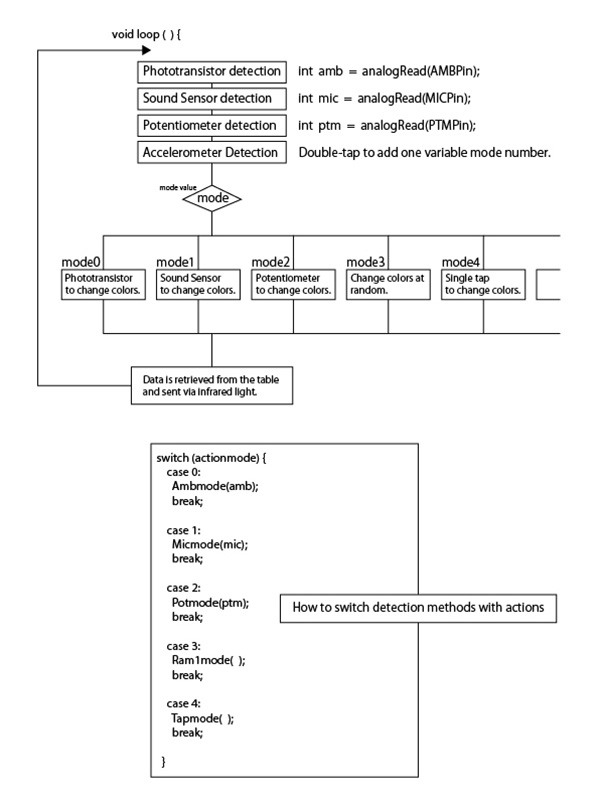
Building a program to switch lighting colors
Next, I switched lighting colors and built a program of lighting patterns that flickered and flickered colorfully like a flame.
Binary Digits
| value | 4bit | value | 4bit |
|---|---|---|---|
| 0 | 0000 | 1 | 0001 |
| 2 | 0010 | 3 | 0011 |
| 4 | 0100 | 5 | 0101 |
| 6 | 0110 | 7 | 0111 |
| 8 | 1000 | 9 | 1001 |
| A | 1010 | B | 1011 |
| C | 1100 | D | 1101 |
| E | 1110 | F | 1111 |
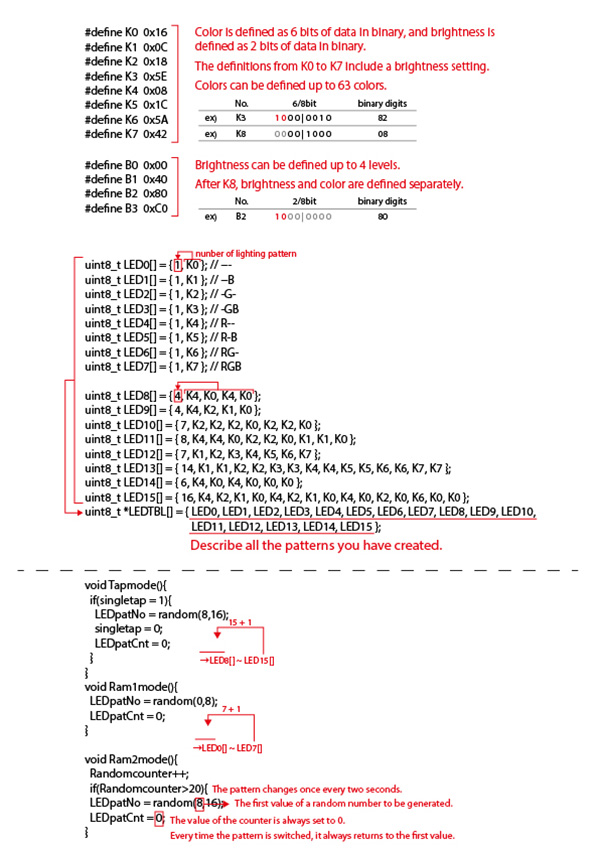
#define K0 ~ K63
| value | 6/8bit | binary digits | value | 6/8bit | binary digits |
|---|---|---|---|---|---|
| K0 | (10) 00 / 0000 | 00 | K1 | (10) 00 / 0001 | 81 |
| K2 | (10) 00 / 0010 | 82 | K3 | (10) 00 / 0011 | 83 |
| K4 | (10) 00 / 0100 | 00 | K5 | (10) 00 / 0101 | 85 |
| K6 | (10) 00 / 0110 | 00 | K7 | (10) 00 / 0111 | 87 |
| K8 | (00) 00 / 1000 | 08 | K9 | (10) 00 / 1001 | 09 |
| K10 | (00) 00 / 1010 | 0A | K11 | (00) 00 / 1011 | 0B |
| K12 | (00) 00 / 1100 | 0C | K13 | (00) 00 / 1101 | 0D |
| K14 | (00) 00 / 1110 | 0E | K15 | (00) 00 / 1111 | 0F |
| K16 | (00) 01 / 0000 | 10 | K17 | (00) 01 / 0001 | 11 |
| K18 | (00) 01 / 0010 | 12 | K19 | (00) 01 / 0011 | 13 |
| K20 | (00) 01 / 0100 | 14 | K21 | (00) 01 / 0101 | 15 |
| K22 | (00) 01 / 0110 | 16 | K23 | (00) 01 / 0111 | 17 |
| K24 | (00) 01 / 1000 | 18 | K25 | (00) 01 / 1001 | 19 |
| K26 | (00) 01 / 1010 | 1A | K27 | (00) 01 / 1011 | 1B |
| K28 | (00) 01 / 1100 | 1C | K29 | (00) 01 / 1101 | 1D |
| K30 | (00) 01 / 1110 | 1E | K31 | (00) 01 / 1111 | 1F |
| K32 | (00) 10 / 0000 | 20 | K33 | (00) 10 / 0001 | 21 |
| K34 | (00) 10 / 0010 | 22 | K35 | (00) 10 / 0011 | 23 |
| K36 | (00) 10 / 0100 | 24 | K37 | (00) 10 / 0101 | 25 |
| K38 | (00) 10 / 0110 | 26 | K39 | (00) 10 / 0111 | 27 |
| K40 | (00) 10 / 1000 | 28 | K41 | (00) 10 / 1001 | 29 |
| K42 | (00) 10 / 1010 | 2A | K43 | (00) 10 / 1011 | 2B |
| K44 | (00) 10 / 1100 | 2C | K45 | (00) 10 / 1101 | 2D |
| K46 | (00) 10 / 1110 | 2E | K47 | (00) 10 / 1111 | 3F |
| K48 | (00) 11 / 0000 | 30 | K49 | (00) 11 / 0001 | 31 |
| K50 | (00) 11 / 0010 | 32 | K51 | (00) 11 / 0011 | 33 |
| K52 | (00) 11 / 0100 | 34 | K53 | (00) 11 / 0101 | 35 |
| K54 | (00) 11 / 0110 | 36 | K55 | (00) 11 / 0111 | 37 |
| K56 | (00) 11 / 1000 | 38 | K57 | (00) 11 / 1001 | 39 |
| K58 | (00) 11 / 1010 | 3A | K59 | (00) 11 / 1011 | 3B |
| K60 | (00) 11 / 1100 | 3C | K61 | (00) 11 / 1101 | 3D |
| K62 | (00) 11 / 1110 | 3E | K63 | (00) 11 / 1111 | 3F |
(3) power supply
I decided to use a rechargeable lithium battery and charging circuit to run the ESP32’s circuitry.
lithium battery

charging circuit
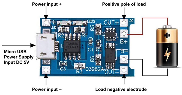
breadboard diagram
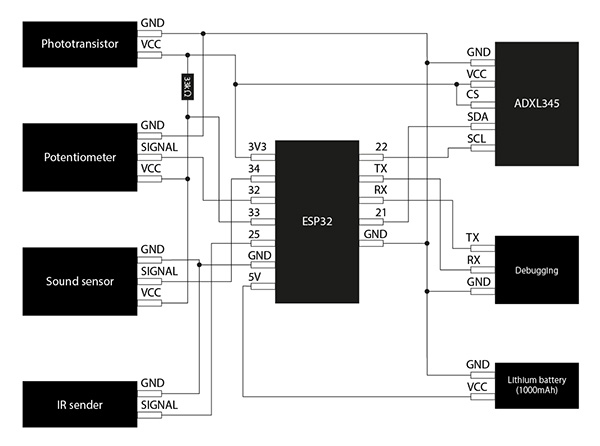
breadboard photo
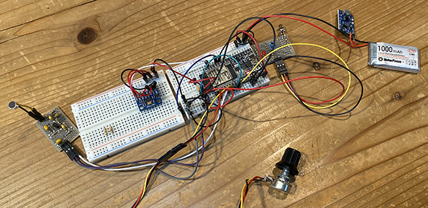
(4) Programming
//******************************************************************//
//  ESP32  Send IR DATA automatically
//    2020.6.7
//    ESP32_IRsend06_1.ino
//     Send data = Sellect Table DATA by tapping accelerometer randomly
//     ADXL345(I2C) accelerometer
//******************************************************************//

#include "driver/rmt.h"

const int rmtDataLength = 34;        // NEC format data length 34 bit
rmt_item32_t rmtData[rmtDataLength]; // data to send

const rmt_channel_t channel = RMT_CHANNEL_0;
const gpio_num_t irPin = GPIO_NUM_25;

//****************************************//
const gpio_num_t PTMPin = GPIO_NUM_32; // Potentiometer input
const gpio_num_t AMBPin = GPIO_NUM_33; // Ambient senser
const gpio_num_t MICPin = GPIO_NUM_34; // Audio senser
//****************************************//

const int leaderOnUs = 9000;
const int leaderOffUs = 4500;
const int dataOnUs = 560;
const int data1OffUs = 1690;
const int data0OffUs = 560;
const int stopbitOnUs = 560;
const int stopbitOffUs = 0x7fff;

//*************************************************************//
//   LED Brink Pattern Table definition
//*************************************************************//

/* LED pattern variable */
int LEDpatNo = 0; //LED pattern
int LEDpatCnt = 0; //LED data counter
int actionmode = 0;//インプットデバイスを使って色を変える
int singletap = 0;//setupでもloopの中でも使えるように
int Randomcounter = 0;//何回に一回ランダム表示を切り替えるか

/* Define KEY Code */
#define K0  0x16
#define K1  0x0C
#define K2  0x18
#define K3  0x5E
#define K4  0x08
#define K5  0x1C
#define K6  0x5A
#define K7  0x42

/* define LED pattern */
uint8_t LED0[] = { 1, K0 }; // ---
uint8_t LED1[] = { 1, K1 }; // --B
uint8_t LED2[] = { 1, K2 }; // -G-
uint8_t LED3[] = { 1, K3 }; // -GB
uint8_t LED4[] = { 1, K4 }; // R--
uint8_t LED5[] = { 1, K5 }; // R-B
uint8_t LED6[] = { 1, K6 }; // RG-
uint8_t LED7[] = { 1, K7 }; // RGB

uint8_t LED8[] = { 4, K4, K0, K4, K0 }; //
uint8_t LED9[] = { 4, K4, K2, K1, K0 }; //
uint8_t LED10[] = { 7, K2, K2, K2, K0, K2, K2, K0 }; //
uint8_t LED11[] = { 8, K4, K4, K0, K2, K2, K0, K1, K1, K0 }; //
uint8_t LED12[] = { 7, K1, K2, K3, K4, K5, K6, K7 }; //
uint8_t LED13[] = { 14, K1, K1, K2, K2, K3, K3, K4, K4, K5, K5, K6, K6, K7, K7 }; //
uint8_t LED14[] = { 6, K4, K0, K4, K0, K0, K0 }; //
uint8_t LED15[] = { 16, K4, K2, K1, K0, K4, K2, K1, K0, K4, K0, K2, K0, K6, K0, K0 }; // Pattern15
uint8_t *LEDTBL[] = { LED0, LED1, LED2, LED3, LED4, LED5, LED6, LED7,
                      LED8, LED9, LED10, LED11, LED12, LED13, LED14, LED15 };
//*** End of LED Brink Pattern Table definition ****************************//

//***** Accelerometer *****
#include <Wire.h>
#include <ADXL345.h>

ADXL345 adxl;

/* send NEC format remote control data */
void sendData(uint16_t customCode, uint8_t dataCode) {
  /* leader code 1bit: ON 9000us, OFF 4500us */
  rmtData[0].duration0 = leaderOnUs;
  rmtData[0].level0 = 1;
  rmtData[0].duration1 = leaderOffUs;
  rmtData[0].level1 = 0;

  /*
   * custom code 16 bit
   * INPUT series: b15 b14 b13 b12 b11 b10 b09 b08 b07 b06 b05 b04 b03 b02 b01 b00
   * SEND  series: b08 b09 b10 b11 b12 b13 b14 b15 b00 b01 b02 b03 b04 b05 b06 b07
   */
  for (int i = 0; i < 2; i++) {
    for (int j = 0; j < 8; j++) {
      /*
       * 1: ON 560us + OFF 1690us
       * 0: ON 560us + OFF  560us
      */
      rmtData[8 * i + j + 1].duration0 = dataOnUs;
      rmtData[8 * i + j + 1].level0 = 1;
      if (customCode & (1 << ((1 - i) * 8 + j))) {
        rmtData[8 * i + j + 1].duration1 = data1OffUs;
      } else {
        rmtData[8 * i + j + 1].duration1 = data0OffUs;
      }
      rmtData[8 * i + j + 1].level1 = 0;
    }
  }

  /*
   * data code 8bit
   * INPUT series: b7 b6 b5 b4 b3 b2 b1 b0
   * SEND  series: b0 b1 b2 b3 b4 b5 b6 b7 ~b0 ~b1 ~b2 ~b3 ~b4 ~b5 ~b6 ~b7
   */
  for (int i = 0; i < 8; i++) {
    rmtData[i + 17].duration0 = dataOnUs;
    rmtData[i + 25].duration0 = dataOnUs;
    rmtData[i + 17].level0 = 1;
    rmtData[i + 25].level0 = 1;
    if (dataCode & (1 << i)) {
      rmtData[i + 17].duration1 = data1OffUs;
      rmtData[i + 25].duration1 = data0OffUs;
    } else {
      rmtData[i + 17].duration1 = data0OffUs;
      rmtData[i + 25].duration1 = data1OffUs;
    }
    rmtData[i + 17].level1 = 0;
    rmtData[i + 25].level1 = 0;
  }

  /* stop bit 1bit: ON 560 */
  rmtData[33].duration0 = stopbitOnUs;
  rmtData[33].level0 = 1;
  rmtData[33].duration1 = stopbitOffUs;
  rmtData[33].level1 = 0;

  rmt_write_items(channel, rmtData, rmtDataLength, true);
}

//*************************************************//
//     Print 8bit data in HEX to console
//*************************************************//
void hexprint(uint8_t data){
  char HEXTBL[] = {'0', '1', '2', '3', '4', '5', '6', '7',
                   '8', '9', 'A', 'B', 'C', 'D', 'E', 'F' };
  Serial.print(HEXTBL[ (data & 0xF0) >> 4 ]);
  Serial.print(HEXTBL[ (data & 0x0F)]);
}

//*************************************************//
//      MAIN PROCESS
//*************************************************//

void setup() {

  rmt_config_t rmtConfig;
  rmtConfig.rmt_mode = RMT_MODE_TX;  // transmit mode
  rmtConfig.channel = channel;  // channel to use 0 - 7
  rmtConfig.clk_div = 80;  // clock divider 1 - 255. source clock is 80MHz -> 80MHz/80 = 1MHz -> 1 tick = 1 us
  rmtConfig.gpio_num = irPin; // pin to use
  rmtConfig.mem_block_num = 1; // memory block size

  rmtConfig.tx_config.loop_en = 0; // no loop
  rmtConfig.tx_config.carrier_freq_hz = 38000;  // IR remote controller uses 38kHz carrier frequency
  rmtConfig.tx_config.carrier_duty_percent = 33; // duty
  rmtConfig.tx_config.carrier_level =  RMT_CARRIER_LEVEL_HIGH; // carrier level
  rmtConfig.tx_config.carrier_en = 1;  // carrier enable
  rmtConfig.tx_config.idle_level =  RMT_IDLE_LEVEL_LOW ; // signal level at idle
  rmtConfig.tx_config.idle_output_en = 1;  // output if idle

  rmt_config(&rmtConfig);
  rmt_driver_install(rmtConfig.channel, 0, 0);

  Serial.begin(115200);
  pinMode( PTMPin, INPUT );
  pinMode( AMBPin, INPUT );
  pinMode( MICPin, INPUT );

  adxl.powerOn();

  //set activity/ inactivity thresholds (0-255)
  adxl.setActivityThreshold(75); //62.5mg per increment
  adxl.setInactivityThreshold(75); //62.5mg per increment
  adxl.setTimeInactivity(10); // how many seconds of no activity is inactive?

  //look of activity movement on this axes - 1 == on; 0 == off
  adxl.setActivityX(1);
  adxl.setActivityY(1);
  adxl.setActivityZ(1);

  //look of inactivity movement on this axes - 1 == on; 0 == off
  adxl.setInactivityX(1);
  adxl.setInactivityY(1);
  adxl.setInactivityZ(1);

  //look of tap movement on this axes - 1 == on; 0 == off
  adxl.setTapDetectionOnX(0);
  adxl.setTapDetectionOnY(0);
  adxl.setTapDetectionOnZ(1);

  //set values for what is a tap, and what is a double tap (0-255)
  adxl.setTapThreshold(50); //62.5mg per increment
  adxl.setTapDuration(15); //625μs per increment
  adxl.setDoubleTapLatency(80); //1.25ms per increment
  adxl.setDoubleTapWindow(200); //1.25ms per increment

  //set values for what is considered freefall (0-255)
  adxl.setFreeFallThreshold(7); //(5 - 9) recommended - 62.5mg per increment
  adxl.setFreeFallDuration(45); //(20 - 70) recommended - 5ms per increment

  //setting all interupts to take place on int pin 1
  //I had issues with int pin 2, was unable to reset it
  adxl.setInterruptMapping( ADXL345_INT_SINGLE_TAP_BIT,   ADXL345_INT1_PIN );
  adxl.setInterruptMapping( ADXL345_INT_DOUBLE_TAP_BIT,   ADXL345_INT1_PIN );
  adxl.setInterruptMapping( ADXL345_INT_FREE_FALL_BIT,    ADXL345_INT1_PIN );
  adxl.setInterruptMapping( ADXL345_INT_ACTIVITY_BIT,     ADXL345_INT1_PIN );
  adxl.setInterruptMapping( ADXL345_INT_INACTIVITY_BIT,   ADXL345_INT1_PIN );

  //register interupt actions - 1 == on; 0 == off
  adxl.setInterrupt( ADXL345_INT_SINGLE_TAP_BIT, 1);
  adxl.setInterrupt( ADXL345_INT_DOUBLE_TAP_BIT, 1);
  adxl.setInterrupt( ADXL345_INT_FREE_FALL_BIT,  1);
  adxl.setInterrupt( ADXL345_INT_ACTIVITY_BIT,   1);
  adxl.setInterrupt( ADXL345_INT_INACTIVITY_BIT, 1);

  /* initialize variables */
  LEDpatNo = 0;
  LEDpatCnt = 0;
}

void loop() {
  //光と音の検出
  int amb = analogRead(AMBPin);
  int mic = analogRead(MICPin);
  int ptm = analogRead(PTMPin);

//加速度センサーの検出
  //Boring accelerometer stuff
  //int x,y,z;
  //adxl.readXYZ(&x, &y, &z); //read the accelerometer values and store them in variables  x,y,z

  // Output x,y,z values - Commented out
  //Serial.print(x);
  //Serial.print(y);
  //Serial.println(z);

  //read interrupts source and look for triggerd actions

  //getInterruptSource clears all triggered actions after returning value
  //so do not call again until you need to recheck for triggered actions
   byte interrupts = adxl.getInterruptSource();

  // freefall
  //if(adxl.triggered(interrupts, ADXL345_FREE_FALL)){
    //Serial.println("Free-fall detected.");           //自由落下を検出しました。
    //add code here to do when freefall is sensed
  //}

  //inactivity
  //if(adxl.triggered(interrupts, ADXL345_INACTIVITY)){
    //Serial.println("No motion detected.");          //動きを検出しなかった。
     //add code here to do when inactivity is sensed
  //}

  //activity
  //if(adxl.triggered(interrupts, ADXL345_ACTIVITY)){
    //Serial.println("Motion detected.");                 //動きを検出しました。
//    LEDpatNo = random( 0, 7 );
//    LEDpatCnt = 0;
  //}

  //double tap
  if(adxl.triggered(interrupts, ADXL345_DOUBLE_TAP)){
    Serial.println("Double tap detected.");           //ダブルタップを検出しました。
    actionmode = actionmode+1;
    if(actionmode>5){//ここを4から5に変えないとRam2までいかなかった
      actionmode = 0;//ダブルタップをしたらアクションモードが1つずつ変わる
    }
    LEDpatCnt = 0;//テーブルが変わってもいいようにしておく
  }

/*
  //tap
  if(adxl.triggered(interrupts, ADXL345_SINGLE_TAP)){
    Serial.println("Single tap detected.");            //シングルタップを検出しました。
    LEDpatNo = random( 8, 15 );
    LEDpatCnt = 0;
  }
*/

  //tap
  if(adxl.triggered(interrupts, ADXL345_SINGLE_TAP) && !adxl.triggered(interrupts, ADXL345_DOUBLE_TAP)){
    Serial.println("Single tap detected.");            //シングルタップを検出しました。
    singletap = 1;//シングルタップされたことを記憶するだけ
    LEDpatCnt = 0;
  }

  //actionmodeを切り替える
  switch(actionmode){
    case 0:
      Ambmode(amb);
      break;

    case 1:
      Micmode(mic);
      break;

    case 2:
      Tapmode();
      break;

    case 3:
      Potmode(ptm);
      break;

    case 4:
      Ram1mode();
      break;

    case 5:
      Ram2mode();
      break;
  }

//表示
/* Send LED data sequncially in the LED Pattern Table */
  uint8_t *p; // Define KeyPatternAddress pointer
  p = LEDTBL[LEDpatNo]; // Set pointer address
  int i = *p; // Get pattern length
  uint8_t kdata = *(p + LEDpatCnt + 1); // get Keydata
  sendData(0x00ff, kdata);
//  hexprint(kdata);
//  Serial.print(" ");
  LEDpatCnt++;
  if ( LEDpatCnt > i-1 ) {
    LEDpatCnt = 0;
//    Serial.println();
  }
//  delay(30);
}

void Micmode(int analogdata3){  //音センサーで制御するプログラム
  if(analogdata3<500){
    LEDpatNo = 0;
  }
  else if(analogdata3<1000){
    LEDpatNo = 1;
  }
  else if(analogdata3<1500){
    LEDpatNo = 2;
  }
  else if(analogdata3<2000){
    LEDpatNo = 3;
  }
  else if(analogdata3<2500){
    LEDpatNo = 4;
  }
  else if(analogdata3<3000){
    LEDpatNo = 5;
  }
  else if(analogdata3<3500){
    LEDpatNo = 6;
  }
  else{
    LEDpatNo = 7;
  }

  LEDpatCnt = 0;
}

void Ambmode(int analogdata2){  //光センサーで制御するプログラム
  if(analogdata2<500){
    LEDpatNo = 0;
  }
  else if(analogdata2<1000){
    LEDpatNo = 1;
  }
  else if(analogdata2<1500){
    LEDpatNo = 2;
  }
  else if(analogdata2<2000){
    LEDpatNo = 3;
  }
  else if(analogdata2<2500){
    LEDpatNo = 4;
  }
  else if(analogdata2<3000){
    LEDpatNo = 5;
  }
  else if(analogdata2<3500){
    LEDpatNo = 6;
  }
  else{
    LEDpatNo = 7;
  }

  LEDpatCnt = 0;
}

void Potmode(int analogdata1){  //ポテンショメータで制御するプログラム
  if(analogdata1<500){
    LEDpatNo = 0;
  }
  else if(analogdata1<1000){
    LEDpatNo = 1;
  }
  else if(analogdata1<1500){
    LEDpatNo = 2;
  }
  else if(analogdata1<2000){
    LEDpatNo = 3;
  }
  else if(analogdata1<2500){
    LEDpatNo = 4;
  }
  else if(analogdata1<3000){
    LEDpatNo = 5;
  }
  else if(analogdata1<3500){
    LEDpatNo = 6;
  }
  else{
    LEDpatNo = 7;
  }

  LEDpatCnt = 0;
}

void Tapmode(){
  if(singletap = 1){
    LEDpatNo = random(8,16);
    singletap = 0;
    LEDpatCnt = 0;
  }
}
void Ram1mode(){
  LEDpatNo = random(0,8);
  LEDpatCnt = 0;
}

void Ram2mode(){
  Randomcounter++;
  if(Randomcounter>20){//約2秒に1回パターンが変わる
    LEDpatNo = random(8,16);
    LEDpatCnt = 0;
    Randomcounter = 0;
  }
}
I was able to double-tap the ADXL345 and see that the lighting patterns switched, and a single tap would switch one color at a time.
I also observed that the color of each input device changed depending on its input value.
Finding the Problem
① IR communication range
I verified the communication potential distance between the earrings we created and the obi clasp breadboard circuit and found that the two devices did not work when they were more than 300 mm apart.
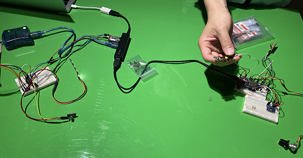
I also needed to emit infrared light to the two earrings worn in the ear, so we considered the device based on the angle and distance between the obi clasp and the earrings.
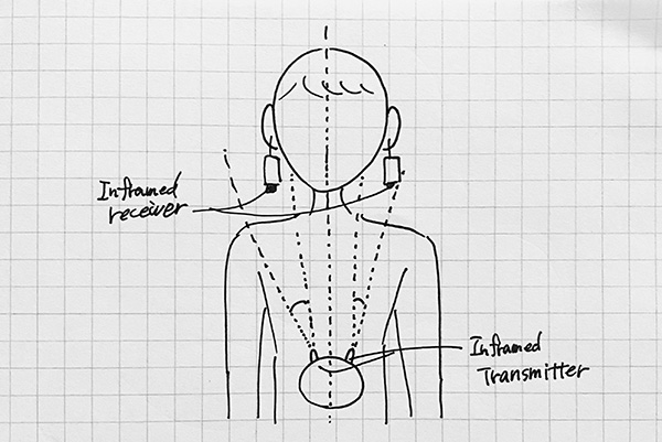
So I assembled a device with two infrared transmitter LEDs. The infrared transmitter mounted was a 5mm Infrared LED 940nm OSI5LA5453B.
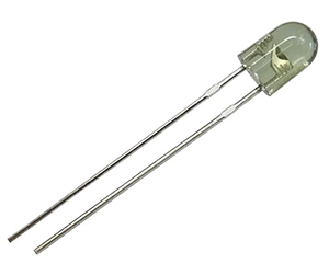
| Function | Numeric Value |
|---|---|
| Inframed emission distance | about 1.5m |
| Inframed center frequency | 940nm |
| Inframed emission angle | 15 degree |
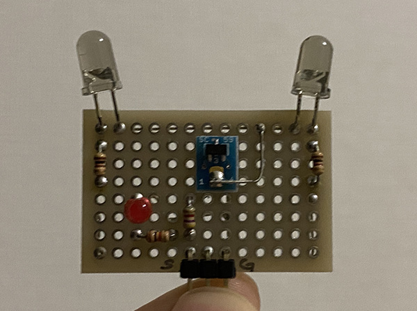
schematic
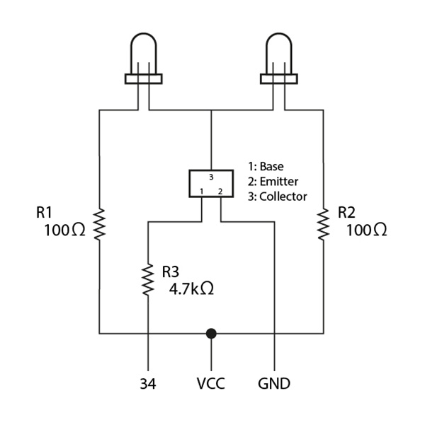
Calculation of Resistor and current amplification factor of transistors
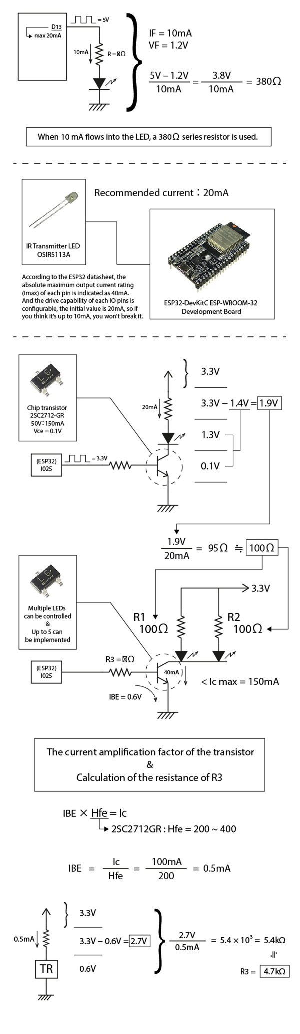
I actually tested it by releasing the device, and we were able to confirm that it was working from a distance of more than about one meter away.
② Changing the sound sensor
I changed the microphone part of the sound sensor to a smaller device. I used [Electret Condenser Microphone (ECM) WM-61A equivalent with lead pin].
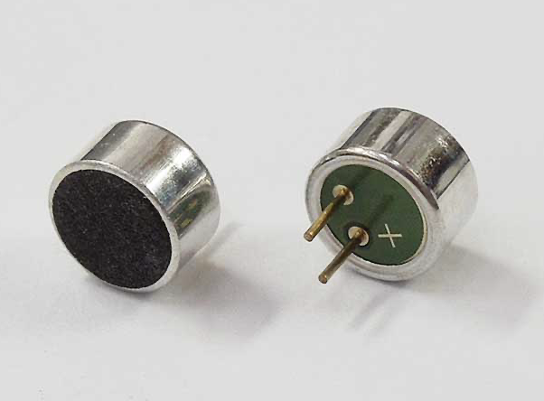
schematic
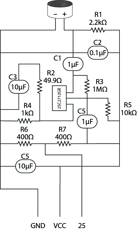
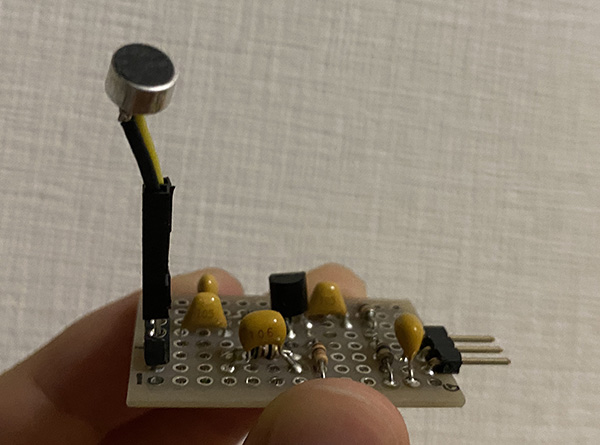
I confirmed that the sound sensor works.
③ Neopixel diffusers
I selected Neopixel’s diffusers to create a luminous effect similar to that of a paper lantern. At first, I was going to use [Japanese paper] as the diffuser, but I thought that it is thicker and would make the accessory heavier, so I decided on a different material. So I chose tracing paper for the diffusion board. The thickness of tracing paper is [75g/m2].
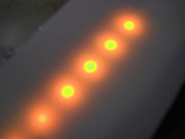
3. Links to Files and Code
Programming
- ATtiny85 IR Receiver [ino]
- ATtiny85 SoftwareSerial [ino]
- ATtiny85 IRreceiver SoftwareSerial [ino]
- Neopixel Sample [ino]
- Earring Neopixel Test [ino]
- Earring Neopixel Test2 [ino]
- Earring Neopixel Test3 [ino]
- Earring Neopixel Test4 [ino]
- ESP32 IRsender [ino]
- ESP32 IRsender Potentiometer [ino]
- ESP32 IRsender Phototransistor [ino]
- ESP32 IRsender Soundsensor [ino]
- ESP32 ADXL345 [ino]
- ESP32 ADXL345 Fix [ino]
- Controller Tapmode [ino]
4. Appendix
- Infrared remote control communication format(JPN)
- Infrared reception of ATtiny85(JPN)
- Trying To Get an IR Receiver to Work with an ATTiny85
- Serial connection: Using a serial console on a Mac(JPN)
- How to use the serial console on a Mac(JPN)
- ATtiny serial communication(JPN)
- Tips for ESP-WROOM-32(JPN)
- I2C communication with ESP32(JPN)