- 2D and 3D Design of the Housing
1. Weekly Brief Summary
This week I used a laser cutter to create the housing of the earrings and Obi clasp. I also made a matching fixture to hang the earrings.
2. Description of Final Proect Work
Earring Part
2D Data Creation
I designed the housing of the earrings based on the assembled board. Note : Unit is [mm].

The design was done in [Adobe Illustrator].
The reason I created [2D data] in [Adobe Illustrator] this time is because it is an application I am accustomed to using in my daily work.
I created the pattern of the blue sea wave to be cut out based on the rendered image which was first modeled in 3D.
The blue ocean wave pattern I used is the one I made for [week2].
I placed the pattern within the range of width=20mm and height=30mm.

The material used for the exterior of the accessories this time was mori no kami, which is made of natural wood. The thickness of this paper is 0.15 mm.
We also decided to put tracing paper (75g/m2) inside to diffuse the light of the Neopixel.
Laser Cutting
I was able to cut out the pattern and diffusion paper with the following parameters.


[mori no kami] Cut Parameter
| Machine | Material | color | Power | Speed | Hz |
|---|---|---|---|---|---|
| trotec speedy 100 | mori no kami | black | 20 | 2.0 | 20000 |
| trotec speedy 100 | mori no kami | red | 20 | 15 | 20000 |
| trotec speedy 100 | mori no kami | blue | 20 | 2.0 | 20000 |
[tracing paper(75g/m2)] Cut Parameter
| Machine | Material | color | Power | Speed | Hz |
|---|---|---|---|---|---|
| trotec speedy 100 | mori no kami | red | 10 | 20 | 20000 |
| trotec speedy 100 | mori no kami | blue | 20 | 10 | 20000 |
Assembly
I used spray glue to glue the two parts that I cut out.

The top plate part of the accessory is made of parts cut out of [MDF 2.5mm].
Since it is not possible to glue one side part to the top plate part in order to incorporate the board, I used a magnetic mechanism to close the lid.
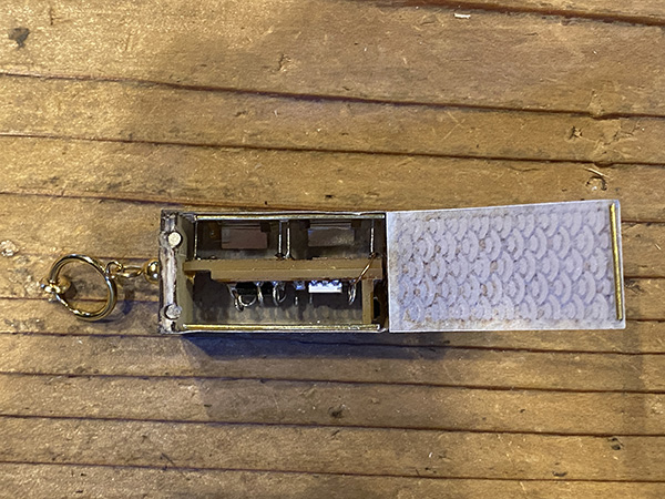


The granular permanent magnet we are using this time will not affect the electric circuit.
Also, some accelerometers can measure magnetic force as well, so it will have an effect on that, but this time it will not have any effect at all because it is not capable of measuring magnetic force.
The assembled accessory was 9g.
We achieved our goal with the 1st spiral to get it below [10g].

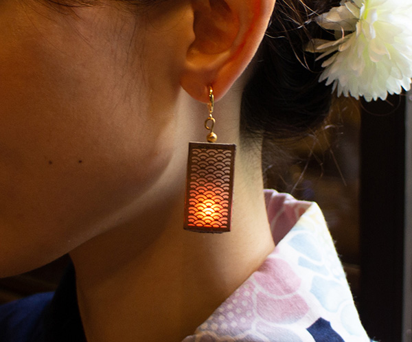
Experiment with Earring Lighting (bright version)
Experiment with Earring Lighting (dark version)
Revisionist Work
The housing of the earring was made of paper, which distorted the shape and left gaps between the surfaces.
So I glued stainless steel rods to the areas where the surfaces meet before assembly to keep the straight shape.
As a result, the Neopixel’s light no longer leaks through the gaps in the box.

Obi clasp Part
3D Data Creation
First I verified the rough design with a sketch. I wanted the overall size of the device to be less than 700mm wide and 700mm long, and less than 500mm high, because the device itself would look awkward if it got too big.
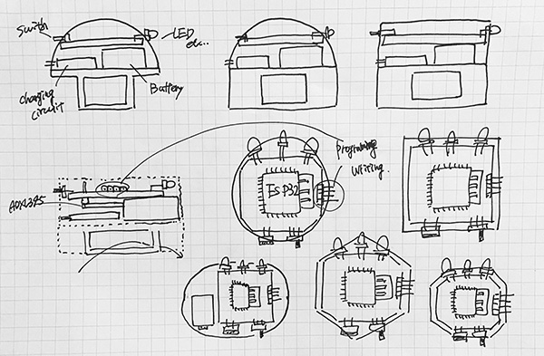
So I first used Fusion360 to model and place the parts for the obi side. I used calipers to measure the electronic components to be used.

↓

I used these numbers to model the electronic components in Fusion360.
STEP(1): Set the base and sketch the size of the model.

STEP(2) : Extrude the sketch you made as per the figures.

STEP(3): Sketch the position of the legs on the side of the extruded body.

STEP(4): Get ready to build the new surface and create the legs.

STEP (5): Make a sketch of the shape of the legs.

STEP(6): Push out the leg-width side.

STEP(7): Increase the legs in a pattern.

STEP(8): Build a new surface to use the mirror function.

STEP(9): Duplicate the legs using the mirror function.

STEP(10): Modify the model to make it closer to ATtiny85.

STEP(11): Finally, drill a hole indicating [GPIO1].

Finish

I used the same procedure to measure and model other electronic components in Fusion360.

Next, I loaded the traced image of the obi strap into the Fusion360 sketch editor. To import the image, click [INSERT] and then [Canvas]. I set a number on the sketch to match the size of the traced image to the actual size before importing.

↓

I traced the board we read and placed the electronic components we created where we extruded the thickness of the board.

↓

After placing the electronic components, I sketched the outer diameter around the whole thing. I made the final outer diameter a hexagon.

After extruding to fit all the electronic components, I did shell processing.

↓

I drilled holes in the location of the electronic components. I also installed a wall to hold the battery box and charging module in position where they would be placed.

Next, I provided a pedestal to hold the board in place. The board can be fixed at a height that does not interfere with the charging module or battery box to be placed.

I also made space for magnets to be used to hold the lids that will be created later.

Finally, a handle is provided for threading the obi.

Final output model
3D printing
I used an Afinia H400 to output the data.
I have embedded the parts into the output data. The lower level has the lithium battery and charging module, and the upper level has the board.
Lower floor

Upper floor

I packed the board and other items into the output banding and checked to see if there were any problems in operation.
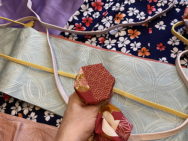
Decoration
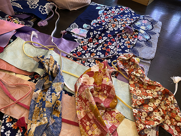
I decided to use a Japanese patterned fabric to decorate the 3D printed body.
The material I prepared for this project was a linen handkerchief, which I purchased at a shop in the Komachi Street shopping district.
Then I went to a kimono/yukata rental shop in advance to choose a handkerchief to use for the exterior of the Obi clasp.
Laser Cutting
I exported the DXF data of the surface from the Fusion360 sketch data and created the imported processed data in Adobe Illustrator.

I was able to cut out a handkerchief with the following parameters.


Handkerchief Cut Parameter
| Machine | Material | color | Power | Speed | Hz |
|---|---|---|---|---|---|
| trotec speedy 100 | mori no kami | black | 30 | 0.9 | 20000 |
Assembly
I used double-sided tape to adhere the cut-out cloth parts to the lid and body parts of the obi closure.


Accessory Fixture Production
I created a fixture to hang the earrings.
The data was created in [Adobe Illustrator].

I used [MDF 2.5mm] for the material. I cut it out using the following parameters.
| Machine | Material | color | Power | Speed | Hz |
|---|---|---|---|---|---|
| trotec speedy 100 | MDF 2.5mm | black | 90 | 0.9 | 20000 |
And I used [aluminum 3mm bars] to make the axis.
The parts to hold the axis in place were designed and 3D printed using Fusion360.
The finish was painted with black drop spray.

3. Description of Important Weekly Learning Outcome
I chose a thicker type of tracing paper so that the light would be more diffused.
The light on the Neopixel diffused to the sides, but the back did not glow depending on the substrate.
2nd In spiral, I wondered if it would be possible to make the substrate with acrylic sheet and copper foil so that the light can reach the back side.
4. Links to Files and Code
5. Appendix
None