- Erectronics Production & Embedded Programming
1. Weekly Brief Summary
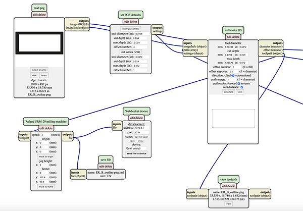
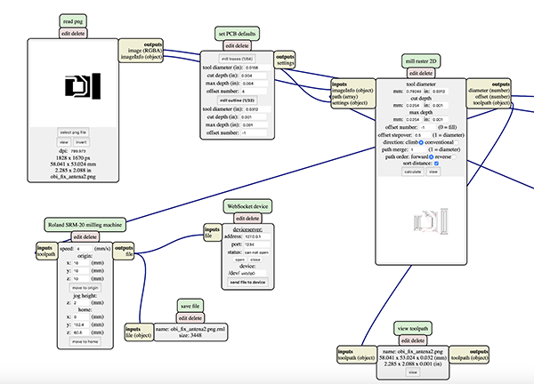
I used Mods to generate G-code from the PNG file of the board’s pattern and outline data, and then used the SRM-20 to perform the cutting process. After that, I wrote the programming to the soldered board and verified the operation.
2. Description of Assignment Work
Earring side
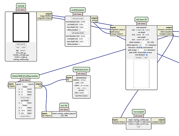
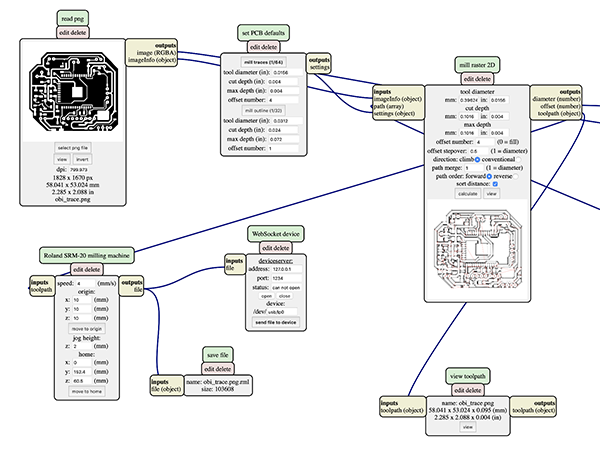
G code generation with Mods
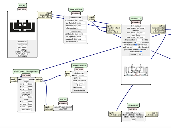
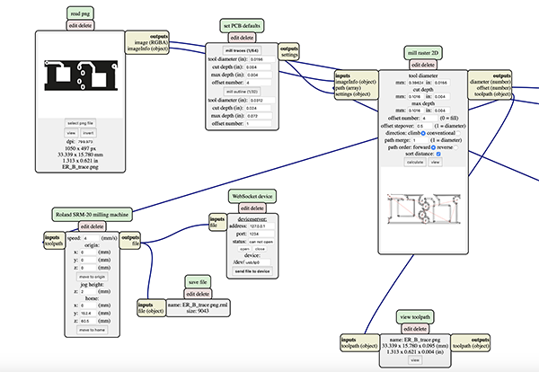
I used the pattern I created, a [PNG] file of outline data to generate the G code from the mods. Right click], [PROGRAMS], [OPEN SERVER PROGRAM], [ROLAND-mill-SRM_20-PCB png] to add the module. Another module was added by [right click], [MODULE], [OPEN SERVER MODULE], [SAVE FILE] to automatically save the file.
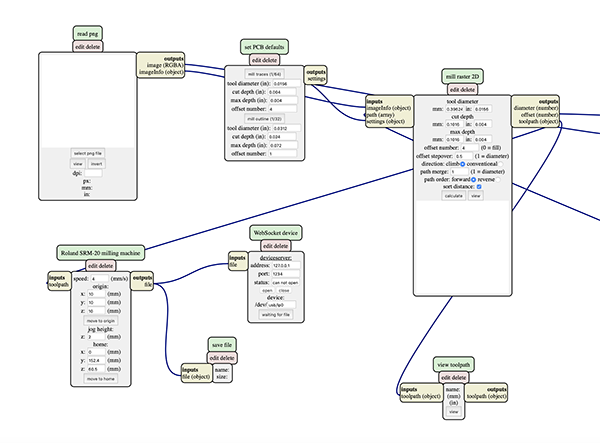
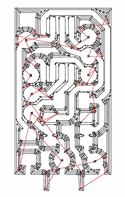
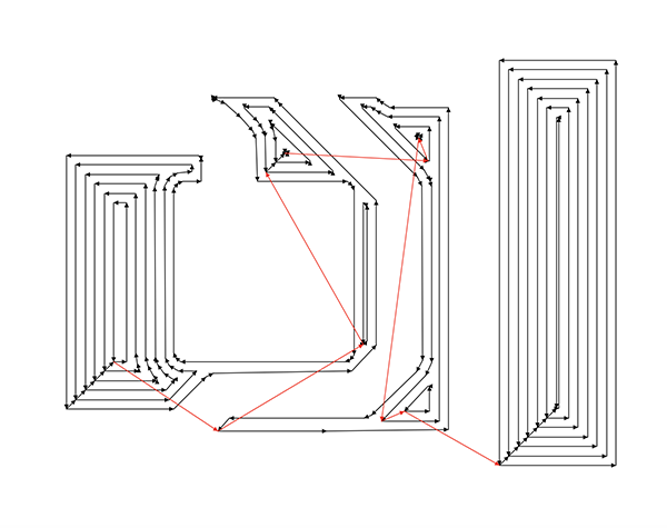
I selected the file to generate the G-code in [select png file] and clicked [calculate] in [mill raster 2D] to export the [rml] file. I clicked [view] and checked from the G-code preview screen to see if the end mill was running through the pattern.
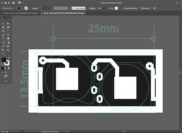
earring pattern
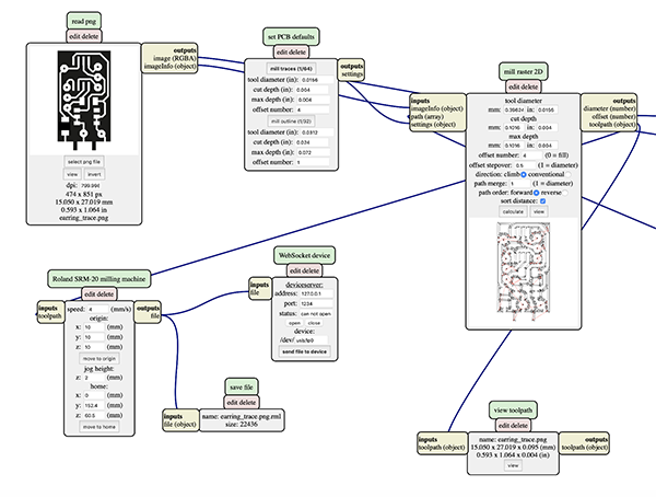
earring outline

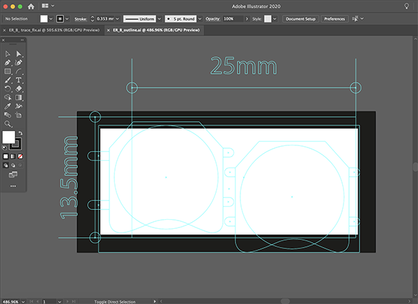
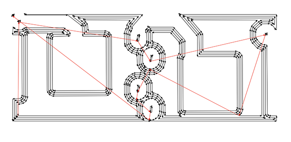
Infrared receiver pattern
Infrared receiver outline
traces files・・・1/64
- In module Roland SRM-20 milling machine Origin
・x0(mm) - 0
・y0(mm) - 0
・z0(mm) - 0…These x0,y0,z0 are for setting up an offset from the origin save in
・z jog heighht - 2…This is the z distance that the mill will go up between the air travellings
・Speed - 4 or 3 mm/s for new end mills
- In module set PCB defaults
・tool diameter (in):0.0156
・cut depth (in): 0.004
・max depth (in): 0.004
・offset number:4
holes / outcut file・・・1/32
- Send the files to the machine
- In Mill Raster 2D module click in Calculate
・The file will be saved automatically into your download folder.
・x0(mm) - 0
・y0(mm) - 0
・z0(mm) - 0
・z jog heighht - 2…This is the z distance that the mill will go up between the air travellings
・Speed - 0.5
- In module set PCB defaults
・tool diameter (in):0.0312
・cut depth (in): 0.024
・max depth (in): 0.072
・offset number:4
I made sure the end mill was running firmly through the pattern.
Cutting with SRM-20
Then I used the SRM-20 to start cutting from the G-code I mentioned earlier.
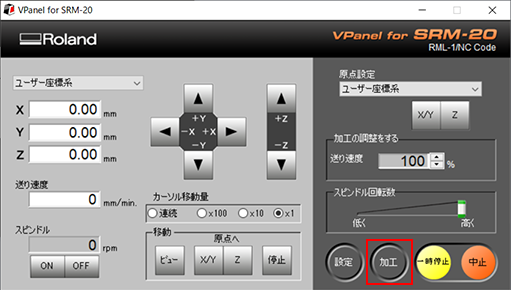
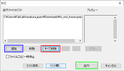
Preparation for Processing
Cutting data of the circuit diagram is read by a VPanel.
Click [Processing] (red circle) in the VPanel to open the Advanced Settings.
There is a possibility that there is a data file that someone processed last time, so click [Delete All] (red frame part).。
Data created earlier are read from [Add] (blue frame part) and click [Output] (green frame part).
↓
Substrate Cutting
Patern Cutting
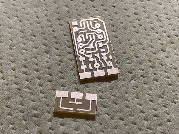
I used a 1/64 bit end mill to cut the pattern on the board.
Outline Cutting
I used a 1/32 bit end mill to cut the outline of the board.
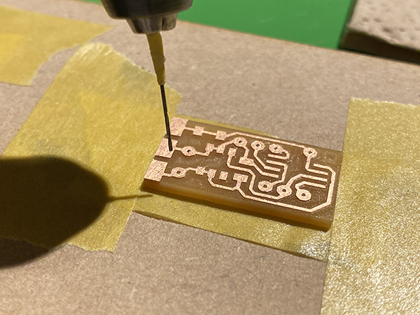
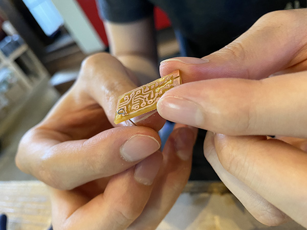
Unnecessary copper foil remains on the edge of the board after cutting, so it must be removed using an ultrasonic cutter.
Substrate Processing
I used a rutor to drill a hole in the cut board. The drill I used is [0.7mm].
I made sure that the tin-plated wire for the program write pins would go through.
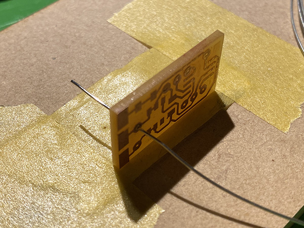
Processing of the pins
I used a pair of radio pliers to create the Q pins.
After soldering the Q pins, I cut off the part of the Q pins that protruded from the board.
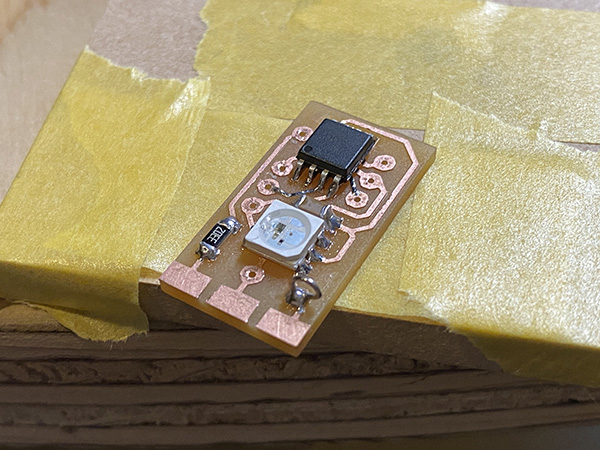
Soldering
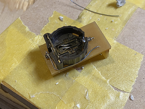
I did the soldering.
The board of the infrared receiver was welded together using solder.
↓
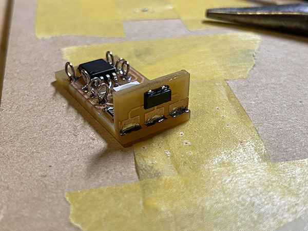
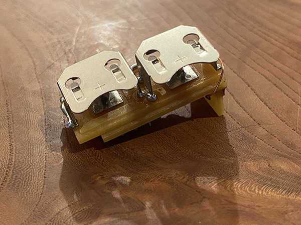
I used double sided tape to attach the battery box to the back side of the board. The hole in the center is for the GND and the left side is for the tin-plated wire that leads to the VCC.
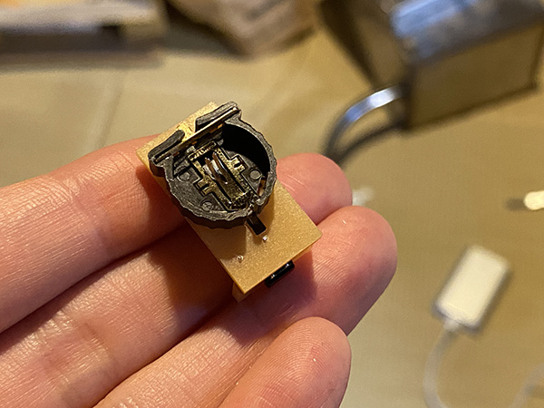
I was careful not to let the tin-plated wire stick out of the board when I soldered it.
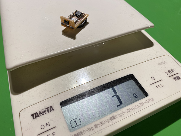
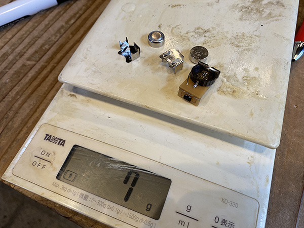
After all the soldering was done, I checked the weight and it was [3g] including the batteries.
Emdebbeging Programming (1)
I used multiple pins to write the program on the earring side. I used FabTiny as a writing machine.
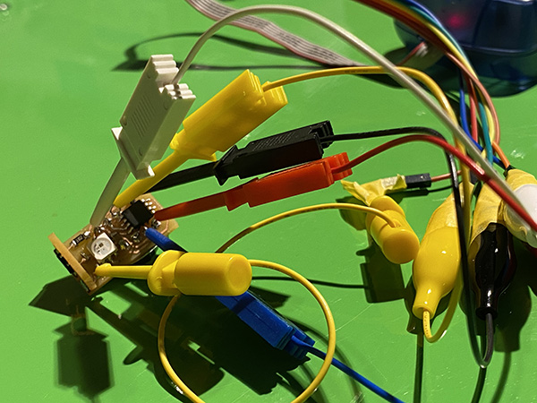
I wrote a program [Earring Neopixel Test2 (ino)] using an infrared remote control module for debugging.
I had built in a program to make the infrared remote control [0] light up, [1] red, [2] green, and [3] blue, but only the blue color of [3] didn’t light up. I found that the single button battery I used [Lithium battery CR1220 from Golden Power] was not enough voltage to display the blue color of the Neopixel. So I had to re-examine the button batteries. (Specified in [Re-examine the batteries])
Re-examine the batteries
I found that my original [Lithium battery CR1220 from Golden Power] did not have enough voltage to make the Neopixel glow blue.
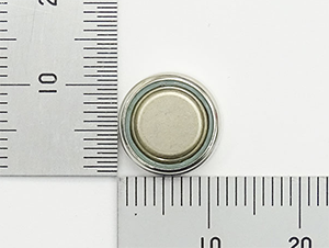
So I decided to review the button battery I use. This time I chose the [Alkaline Button Battery LR44 (Golden Power)]. The voltage per battery is 1.5V.
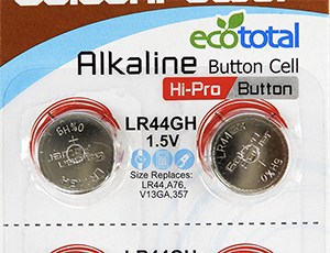
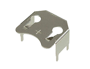
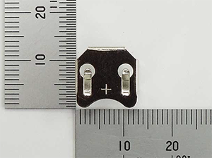
I chose [Battery board attachment holder (metal frame) for LR44] as the battery holder.
| component | vender | cost(JPY) | quanitity | total | notes |
|---|---|---|---|---|---|
| Alkaline Button Battery LR44 (Golden Power) | Akitsukidenshi | ¥100 | 1 | ¥100 | shop link |
| Battery board attachment holder (metal frame) for LR44 | Akitsukidenshi | ¥20 | 2 | ¥40 | shop link |
The combined weight of these parts and the board was [7g]. The target weight of [10g] or less will be achieved.
Creating a battery circuit
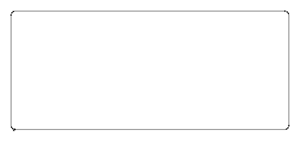
I came up with a battery circuit with new parts. This time I used [Adobe Illustrator] from the beginning instead of EAGLE to create the data. I aimed for a minimum size board based on the battery and battery holder.
Power Supply Board Trace
Power supply board outline
G code generation with Mods
I used the pattern I created, a [PNG] file of outline data to generate the G-code from the mods.
power supply pattern
Power supply circuit outline
soldering
I used SRM-20 to cut and solder the board. I connected the battery circuitry to the VCC/GND pins on the ATtiny85 side with tin plated wires.
Emdebbeging Programming (2)
I wrote Earring Neopixel Test4 [ino] in the earring side. As a timeline, I’ve already written Controller Tapmode [ino] is already written in the board on the banding side.
I have confirmed that the program is working fine and the LEDs on the Neopixel are glowing fine.
Obi Clasp side
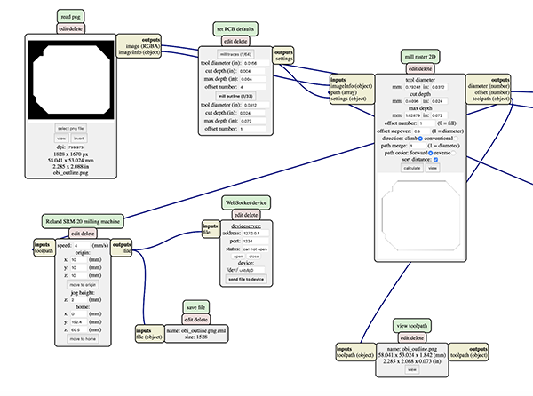
G code generation with Mods
I used the pattern I created, a [PNG] file of outline data to generate the G-code from the mods.
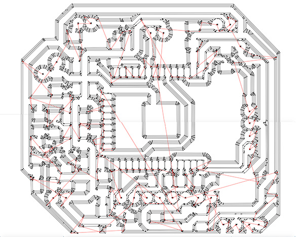
Obi clasp pattern
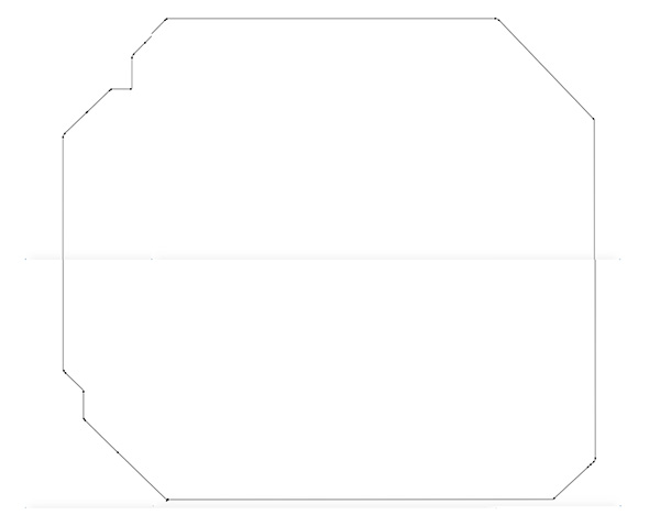
Obi clasp outline
In the case of the obi clasp side board, I needed to remove the copper foil around the antenna, and I used an ultrasonic cutter as well, but the board was torn up.
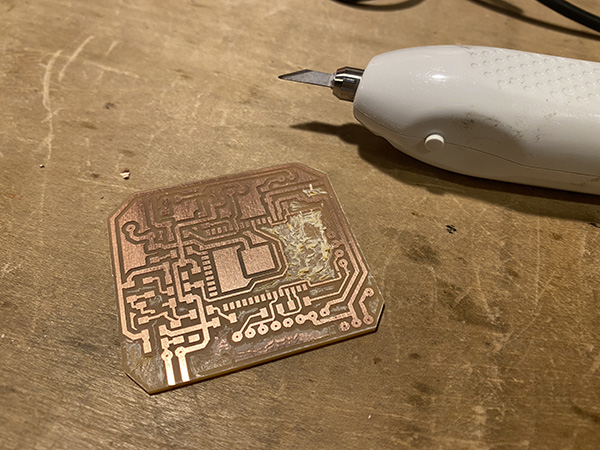
So I created the data to cut around the antenna and the large area to be removed with SRM-20. (Specified in [ESP32 Antenna Processing])
ESP32 Antenna Processing
I decided to write out the cutting data beforehand as cutting data for the part of the cut board where the copper foil was removed using the ultrasonic cutter. I used [Adobe Illustrator] to create the data.
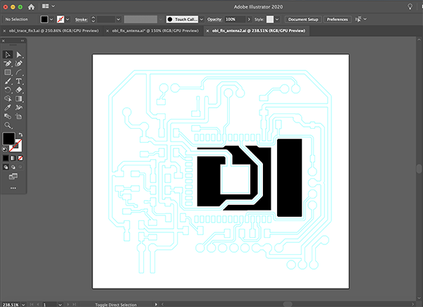
antenna trace
In order to cut all the parts you want to remove, you need to make the following settings. This will cut the copper foil in the excess antenna area.
- cut depth: 0.01 inch (0.254 mm)
- max depth: 0.01 inch (0.254 mm)
- offset number: -1
Soldering
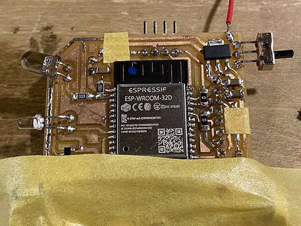
There are many resistors and capacitors on the obi clasp side of the board, so it was difficult to solder them. When I soldered the switches for ESP32 program writing, I put masking tape to prevent short circuit.
↓
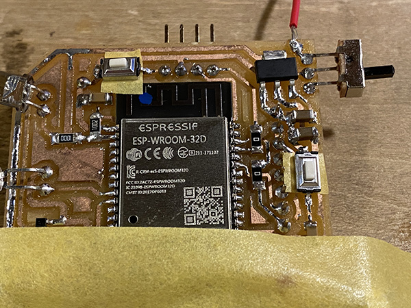
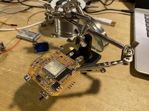
In addition, we used this kind of device to solder through many parts such as the infrared transmitter and the ADXL345, which are soldered through the board.
Emdebbeging Programming
I used a FTDI cable to write the program on the banding side. The pins I connected are GND/TX/RX.
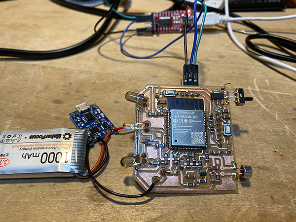
First I wrote a program to light up the LEDs on the ESP32 to make sure there was no problem.
Programminng
//
// hello.ESP32-WROOM.echo.ino
//
// ESP32-WROOM echo hello-world
//
// Neil Gershenfeld 1/6/20
//
// This work may be reproduced, modified, distributed,
// performed, and displayed for any purpose, but must
// acknowledge this project. Copyright is retained and
// must be preserved. The work is provided as is; no
// warranty is provided, and users accept all liability.
//

void setup() {
   Serial.begin(115200);
   }

#define max_buffer 25

void loop() {
   static char chr;
   static char buffer[max_buffer] = {0};
   static int index;
   if (Serial.available()) {
      chr = Serial.read();
      Serial.print("hello.ESP32-WROOM.echo: you typed \"");
      buffer[index++] = chr;
      if (index == (max_buffer-1))
         index = 0;
      Serial.print(buffer);
      Serial.println("\"");
      }
   }
Having verified that the circuitry is OK, I wrote Controller Tapmode [ino] and used the Arduino’s serial monitor and the earring’s breadboard circuitry to check the board for problems.
Debugging with a serial monitor
Debugging with Breadboard Circuits
3. Links to Files and Code
PNG file
![[png]](../../finalproject/files3/obi_antena.png)
![[png]](../../finalproject/files3/battery_circuit_trace.png)
![[png]](../../finalproject/files3/battery_circuit_outline.png)
RML file
- Earring trace date [rml]
- Earring outline date [rml]
- IR receiver trace date [rml]
- IR receiver outline date [rml]
- Obi clasp trace date [rml]
- Obi clasp outline date [rml]
- Obi clasp antena date [rml]
- Battery circuit trace date [rml]
- Battery circuit outline date [rml]
![[rml]](../../finalproject/files3/earring_trace.png.rml)
![[rml]](../../finalproject/files3/earring_outline.png.rml)
![[rml]](../../finalproject/files3/IR_trace.png.rml)
![[rml]](../../finalproject/files3/IR_outline.png.rml)
![[rml]](../../finalproject/files3/obi_trace.png.rml)
![[rml]](../../finalproject/files3/obi_outline.png.rml)
![[rml]](../../finalproject/files3/obi_antena.png.rml)
![[rml]](../../finalproject/files3/battery_circuit_trace.png.rml)
![[rml]](../../finalproject/files3/battery_circuit_outline.png.rml)
Programming
- hello.ESP32-WROOM.echo [ino]
4. Appendix
None