Interface and application programming
1. Weekly Brief Summary
I decided to implement the interface and application using Blynk. So I combined the Blynk interface with my Final Project program to create a system that can control the way the earrings glow via Bluetooth.
2. Weekly Assignment Requirement
Group assignment
- Compare as many tool options as possible.
Individual assignment
- Write an application that interfaces a user with an input and/or output device that you made
Learning outcomes
- Interpret and implement design and programming protocols to create a Graphic
- User Interface (GUI).
Have you?
- Linked to the group assignment page
- Documented your process
- Explained the UI that you made and how you did it
- Outlined problems and how you fixed them
- Included original code (or a screenshot of the app code if that’s not possible)
- Included a ‘hero shot/video’ of your application running with your board
3. Group Assignment Link
Kamakura Group Assignment Week12
4. Description of Assignment Work
(1) Blynk
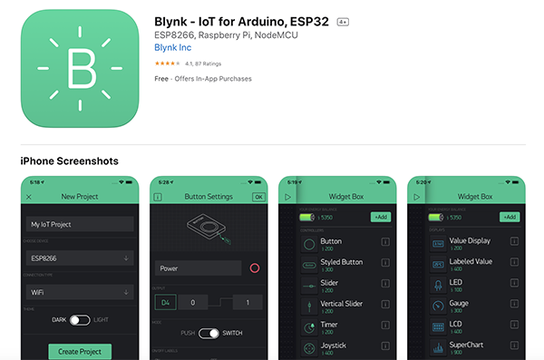
Blynk is a hardware-agnostic IoT platform with white-label mobile apps, private clouds, device management, data analytics, and machine learning.
Blynk has a smartphone-only application that needs to be downloaded from [Appstore] or [Google play].
Breadboard Prototyping
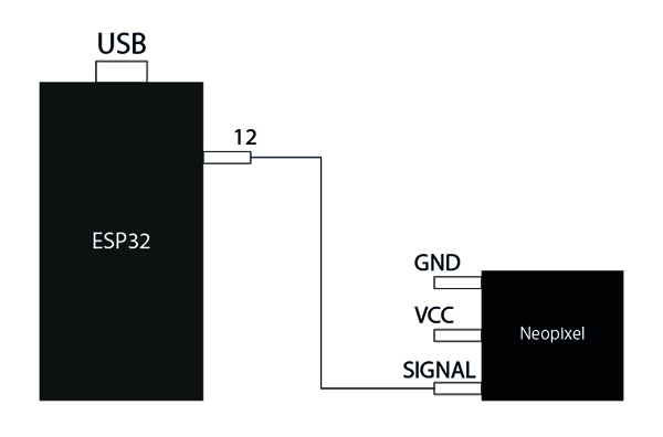
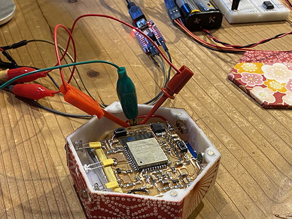
First, I used the FinalProject breadboard circuitry to verify that Bluetooth communication was possible. Here, I connected the Neopixel to an ESP32 development board and controlled the emission color via BLE with Blynk.
I created a breadboard circuit as follows.
Breadboard Schematics
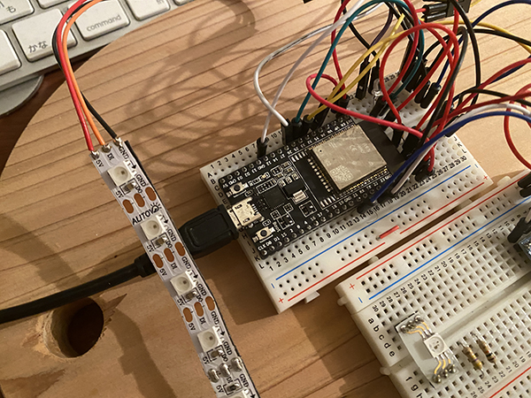
Breadboard circuit photo
Arduino environment preparation and programming
I will be using an Arduino to program the ESP32.
For this reason, I downloaded two different libraries.
I downloaded the above library and then created a program using [Example Sketch] -> [Blynk] -> [Boards_Bluetooth] -> [ESP32_BLE] as a guide.
Programminng
#define BLYNK_PRINT Serial

#define BLYNK_USE_DIRECT_CONNECT

#include <BlynkSimpleEsp32_BLE.h>
#include <BLEDevice.h>
#include <BLEServer.h>

#include <Adafruit_NeoPixel.h>
#include <SPI.h>

#define NUMPIXELS 11 // Number of LEDs in strip

// Here's how to control the LEDs from any two pins:
#define PIN 12

Adafruit_NeoPixel strip = Adafruit_NeoPixel(1, PIN, NEO_GRB + NEO_KHZ800);

int ledR = 0;
int ledG = 0;
int ledB = 0;

// You should get Auth Token in the Blynk App.
char auth[] = "Auth Token";

void setup()
{
  // Debug console
  Serial.begin(9600);

  Serial.println("Waiting for connections...");

  Blynk.begin(auth);
  strip.begin(); // Initialize pins for output
  strip.setBrightness(30);
  strip.show();
}

//ヴァーチャルピンV0
BLYNK_WRITE(V0)
{
  ledR = param[0].asInt();
  ledG = param[1].asInt();
  ledB = param[2].asInt();
  Serial.print(  "ledR: ");
  Serial.print(ledR);
  Serial.print(  " ledG: ");
  Serial.print(ledG);
  Serial.print(  " ledB: ");
  Serial.println(ledB);

  //LED点灯
  for(int i=0;i<NUMPIXELS;i++){
    strip.setPixelColor(i, strip.Color(ledR, ledG, ledB));
  }
  strip.show();
}

void loop()
{
  Blynk.run();
}
Setting up Blynk
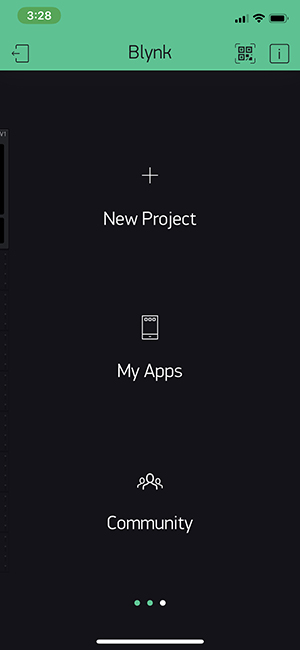
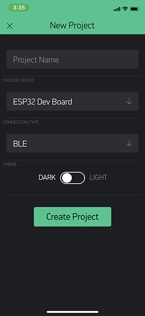
When you open the app you downloaded, you’ll see a screen like this First, click New Project.
Enter any [Project Name] and for [CHOOSE DEVICE], select [ESP32 Dev Board]. Select [BLE] for [CONNECTION TYPE]. Click [Create Project].
| CHOOSE DEVICE | CONNECTION TYPE | Setup completed |
|---|---|---|
 |
 |
 |
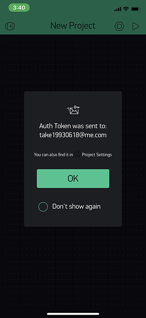
When you start your project, the code [AUTH TOKEN] will be sent to your registered email address. This code is used for generating Arduino code.
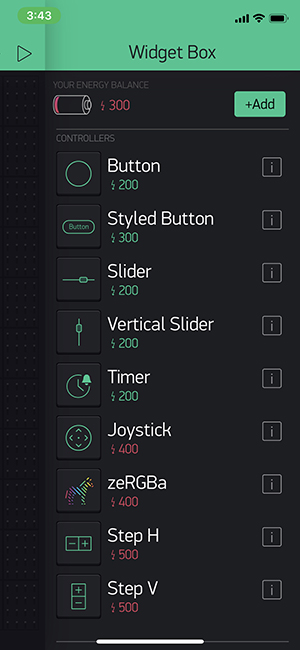
Let’s place the parts to be used on the screen. It is [BLE] and [zeRGBa] to use this time. A list of parts is displayed in the Widget Box when you tap the screen where there is nothing. It is automatically arranged on the screen when I click the part I want to use from there.
| Widget Box | Setup completed |
|---|---|
 |
 |
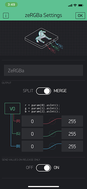
Next, use the zeRGBa widget to allow you to set the color of the LED. Tap the [zeRGBa] icon to display the advanced settings screen. For [OUTPUT], select [MERGE]. Set the minimum value to [0] and the maximum value to [255], respectively. Set [SEND ON RELEASE] to [OFF] so that data can be sent at any time. In this example, the data is output to virtual pin V0.
Blynk BLE Connection
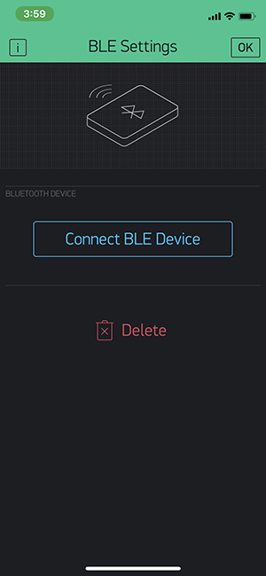
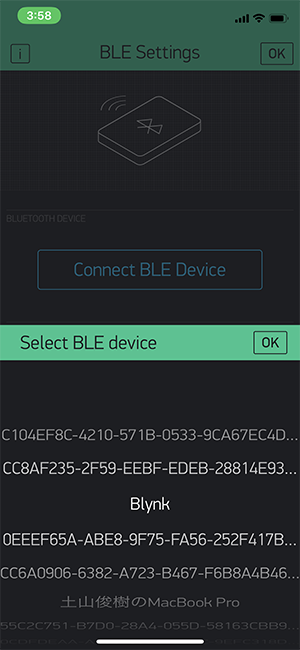
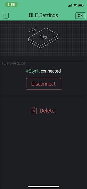
Finally, the ESP32 Development Board and Blynk can be configured for BLE connection. Make sure that the ESP32 Development Board is connected to the power supply. Tap the [BLE] icon to display the detailed settings screen. Click [Connect BLE device] and select [Blynk] when it appears, then click OK. If [BLUETOOTH DEVICE] is set to [#Blynk connected], the connection has been made successfully.
| BLE Setting | Connect BLE device | Blynk connected |
|---|---|---|
 |
 |
 |
Testing
I have confirmed that I can change the color of the Neopixel on Blynk.
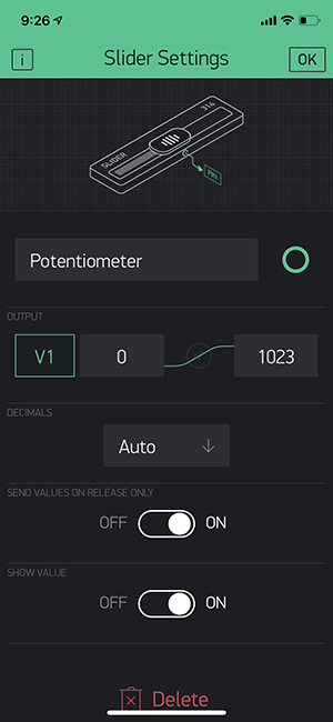
I was going to merge the program I just created with the obi program to create a program that would make the Neopixel in the earring circuit glow, but I needed to change the earring program as well. So I decided to change the virtual device to [Slider] instead of [zeRGBa].
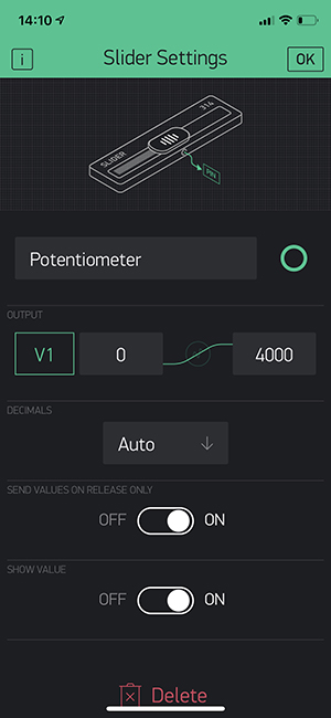
Slider
I selected the virtual device as before. I changed the name of the selected device to [Potentiometer]. I also set the [OUTPUT] pin to [V1]. ( I didn’t set it to [V0] because [zeRGBa] was still on the screen.)
Programminng
The program is based on the one I created for the last [zeRGB]. The virtual pins are set to [V1].
#define BLYNK_PRINT Serial

#define BLYNK_USE_DIRECT_CONNECT

#include <BlynkSimpleEsp32_BLE.h>
#include <BLEDevice.h>
#include <BLEServer.h>

#include <Adafruit_NeoPixel.h>
#include <SPI.h>

#define NUMPIXELS 11 // Number of LEDs in strip

// Here's how to control the LEDs from any two pins:
#define PIN 12

Adafruit_NeoPixel strip = Adafruit_NeoPixel(1, PIN, NEO_GRB + NEO_KHZ800);

int ledR = 0;
int ledG = 0;
int ledB = 0;

// You should get Auth Token in the Blynk App.
char auth[] = "Auth Token";

void setup()
{
  // Debug console
  Serial.begin(9600);

  Serial.println("Waiting for connections...");

  Blynk.begin(auth);
  strip.begin(); // Initialize pins for output
  strip.setBrightness(30);
  strip.show();
}

//ヴァーチャルピンV1
BLYNK_WRITE(V1)
{
  ledR = param[0].asInt();
  ledG = param[1].asInt();
  ledB = param[2].asInt();
  Serial.print(  "ledR: ");
  Serial.print(ledR);
  Serial.print(  " ledG: ");
  Serial.print(ledG);
  Serial.print(  " ledB: ");
  Serial.println(ledB);

  //LED点灯
  for(int i=0;i<NUMPIXELS;i++){
    strip.setPixelColor(i, strip.Color(ledR, ledG, ledB));
  }
  strip.show();
}

void loop()
{
  Blynk.run();
}
Testing
I was able to control the way the Neopixel glows by manipulating [Slider] on Blynk. During testing, we displayed the serial monitor to see how it worked.
Movement
serial monitor
Creating a Program
I incorporated the program I just used into the obi side of the program and created a program that allows you to control the light of the accessory from your smartphone. I changed the program where the potentiometer mode was originally set. So I changed the value of the potentiometer on the Blynk side from [1023] to [4000].
First, prefix [setup] with the following code as the basic definition of [Blynk]. Then, enter the [Auto Token] code from [Blynk] in [char auth[] = “~~~~”].
//***** Blynk *****
#define BLYNK_PRINT Serial

#define BLYNK_USE_DIRECT_CONNECT

#include <BlynkSimpleEsp32_BLE.h>
#include <BLEDevice.h>
#include <BLEServer.h>

#include <SPI.h>

// You should get Auth Token in the Blynk App.
char auth[] = "Auth Token Code";
Next, we add the following code in the [setup] section. Here, we change the value that was originally defined to be read in by the potentiometer to [ptm = param[0].asInt()]. We also need to be able to debug it with the serial monitor.
//***** Blynk *****
  Serial.println("Waiting for connections...");

  Blynk.begin(auth);
}

int ptm;
  BLYNK_WRITE(V1){
    ptm = param[0].asInt();
    Serial.println(ptm);
}
I have redefined the values read by the potentiometer as shown above, so I’ve commented out the parts that I originally defined.
void loop() {
  //光と音の検出
  int amb = analogRead(AMBPin);
  int mic = analogRead(MICPin);
//  int ptm = analogRead(PTMPin);
Finally, we need to write [Blynk.run()] before the potentiometer controlled program.
void Potmode(int analogdata1){//A program controlled by a potentiometer
  Blynk.run();
  if(analogdata1<500){
    LEDpatNo = 0;
  }
  else if(analogdata1<1000){
    LEDpatNo = 1;
  }
  else if(analogdata1<1500){
    LEDpatNo = 2;
  }
  else if(analogdata1<2000){
    LEDpatNo = 3;
  }
  else if(analogdata1<2500){
    LEDpatNo = 4;
  }
  else if(analogdata1<3000){
    LEDpatNo = 5;
  }
  else if(analogdata1<3500){
    LEDpatNo = 6;
  }
  else{
    LEDpatNo = 7;
  }

  LEDpatCnt = 0;
}
Programminng
//******************************************************************//
//  ESP32  Send IR DATA automatically
//    2020.6.7
//    ESP32_IRsend06_1.ino
//     Send data = Sellect Table DATA by tapping accelerometer randomly
//     ADXL345(I2C) accelerometer
//******************************************************************//

#include "driver/rmt.h"

const int rmtDataLength = 34;        // NEC format data length 34 bit
rmt_item32_t rmtData[rmtDataLength]; // data to send

const rmt_channel_t channel = RMT_CHANNEL_0;
const gpio_num_t irPin = GPIO_NUM_25;

//****************************************//
const gpio_num_t PTMPin = GPIO_NUM_32; // Potentiometer input
const gpio_num_t AMBPin = GPIO_NUM_33; // Ambient senser
const gpio_num_t MICPin = GPIO_NUM_34; // Audio senser
//****************************************//

const int leaderOnUs = 9000;
const int leaderOffUs = 4500;
const int dataOnUs = 560;
const int data1OffUs = 1690;
const int data0OffUs = 560;
const int stopbitOnUs = 560;
const int stopbitOffUs = 0x7fff;

//*************************************************************//
//   LED Brink Pattern Table definition
//*************************************************************//

/* LED pattern variable */
int LEDpatNo = 0; //LED pattern
int LEDpatCnt = 0; //LED data counter
int actionmode = 0;//インプットデバイスを使って色を変える
int singletap = 0;//setupでもloopの中でも使えるように
int Randomcounter = 0;//何回に一回ランダム表示を切り替えるか

/* Define 色 Code */
#define K0  0x80
#define K1  0x81
#define K2  0x82
#define K3  0x83
#define K4  0x84
#define K5  0x85
#define K6  0x86
#define K7  0x87
#define K8  0x08
#define K9  0x09
#define K10  0x0A
#define K11  0x0B
#define K12  0x0C
#define K13  0x0D
#define K14  0x0E
#define K15  0x0F
#define K16  0x10
#define K17  0x11
#define K18  0x12
#define K19  0x13
#define K20  0x14

/* Define 明るさ Code */
#define B0  0x00
#define B1  0x40
#define B2  0x80
#define B3  0xC0


/* define LED pattern */
uint8_t LED0[] = { 1, K0 }; // ---
uint8_t LED1[] = { 1, K1 }; // --B
uint8_t LED2[] = { 1, K2 }; // -G-
uint8_t LED3[] = { 1, K3 }; // -GB
uint8_t LED4[] = { 1, K4 }; // R--
uint8_t LED5[] = { 1, K5 }; // R-B
uint8_t LED6[] = { 1, K6 }; // RG-
uint8_t LED7[] = { 1, K7 }; // RGB

uint8_t LED8[] = { 4, K4, K0, K4, K0 }; //
uint8_t LED9[] = { 4, K4, K2, K1, K0 }; //
uint8_t LED10[] = { 7, K2, K2, K2, K0, K2, K2, K0 }; //
uint8_t LED11[] = { 8, K4, K4, K0, K2, K2, K0, K1, K1, K0 }; //
uint8_t LED12[] = { 7, K1, K2, K3, K4, K5, K6, K7 }; //
uint8_t LED13[] = { 14, K1, K1, K2, K2, K3, K3, K4, K4, K5, K5, K6, K6, K7, K7 }; //
uint8_t LED14[] = { 6, K4, K0, K4, K0, K0, K0 }; //
uint8_t LED15[] = { 16, K4, K2, K1, K0, K4, K2, K1, K0, K4, K0, K2, K0, K6, K0, K0 }; // Pattern15

uint8_t LED16[] = { 1, B2+K8 };
uint8_t LED17[] = { 1, B2+K9 };
uint8_t LED18[] = { 1, B2+K10 };
uint8_t LED19[] = { 1, B2+K11 };
uint8_t LED20[] = { 1, B2+K12 };
uint8_t LED21[] = { 1, B2+K13 };

uint8_t LED22[] = { 1, B0+K14 };
uint8_t LED23[] = { 1, B1+K14 };
uint8_t LED24[] = { 1, B2+K14 };
uint8_t LED25[] = { 1, B0+K15 };
uint8_t LED26[] = { 1, B1+K15 };
uint8_t LED27[] = { 1, B2+K15 };
uint8_t LED28[] = { 1, B0+K16 };
uint8_t LED29[] = { 1, B1+K16 };
uint8_t LED30[] = { 1, B2+K16 };
uint8_t LED31[] = { 1, B0+K17 };
uint8_t LED32[] = { 1, B1+K17 };
uint8_t LED33[] = { 1, B2+K17 };
uint8_t LED34[] = { 1, B0+K18 };
uint8_t LED35[] = { 1, B1+K18 };
uint8_t LED36[] = { 1, B2+K18 };

uint8_t *LEDTBL[] = { LED0, LED1, LED2, LED3, LED4, LED5, LED6, LED7, LED8, LED9, LED10, LED11, LED12, LED13, LED14, LED15, LED16, LED17,
LED18, LED19, LED20, LED21, LED22, LED23, LED24, LED25,LED26, LED27, LED28,LED29, LED30, LED31,LED32, LED33,LED34, LED35,LED36};

//*** End of LED Brink Pattern Table definition ****************************//

//***** Blynk *****
#define BLYNK_PRINT Serial

#define BLYNK_USE_DIRECT_CONNECT

#include <BlynkSimpleEsp32_BLE.h>
#include <BLEDevice.h>
#include <BLEServer.h>

//#include <Adafruit_NeoPixel.h>
#include <SPI.h>

//#define NUMPIXELS 11 // Number of LEDs in strip

// Here's how to control the LEDs from any two pins:
//#define PIN 1

//Adafruit_NeoPixel strip = Adafruit_NeoPixel(1, PIN, NEO_GRB + NEO_KHZ800);

//int ledR = 0;
//int ledG = 0;
//int ledB = 0;

// You should get Auth Token in the Blynk App.
char auth[] = "Auth Token";

//***** Accelerometer *****
#include <Wire.h>
#include <ADXL345.h>

ADXL345 adxl;

/* send NEC format remote control data */
void sendData(uint16_t customCode, uint8_t dataCode) {
  /* leader code 1bit: ON 9000us, OFF 4500us */
  rmtData[0].duration0 = leaderOnUs;
  rmtData[0].level0 = 1;
  rmtData[0].duration1 = leaderOffUs;
  rmtData[0].level1 = 0;

  /*
   * custom code 16 bit
   * INPUT series: b15 b14 b13 b12 b11 b10 b09 b08 b07 b06 b05 b04 b03 b02 b01 b00
   * SEND  series: b08 b09 b10 b11 b12 b13 b14 b15 b00 b01 b02 b03 b04 b05 b06 b07
   */
  for (int i = 0; i < 2; i++) {
    for (int j = 0; j < 8; j++) {
      /*
       * 1: ON 560us + OFF 1690us
       * 0: ON 560us + OFF  560us
      */
      rmtData[8 * i + j + 1].duration0 = dataOnUs;
      rmtData[8 * i + j + 1].level0 = 1;
      if (customCode & (1 << ((1 - i) * 8 + j))) {
        rmtData[8 * i + j + 1].duration1 = data1OffUs;
      } else {
        rmtData[8 * i + j + 1].duration1 = data0OffUs;
      }
      rmtData[8 * i + j + 1].level1 = 0;
    }
  }

  /*
   * data code 8bit
   * INPUT series: b7 b6 b5 b4 b3 b2 b1 b0
   * SEND  series: b0 b1 b2 b3 b4 b5 b6 b7 ~b0 ~b1 ~b2 ~b3 ~b4 ~b5 ~b6 ~b7
   */
  for (int i = 0; i < 8; i++) {
    rmtData[i + 17].duration0 = dataOnUs;
    rmtData[i + 25].duration0 = dataOnUs;
    rmtData[i + 17].level0 = 1;
    rmtData[i + 25].level0 = 1;
    if (dataCode & (1 << i)) {
      rmtData[i + 17].duration1 = data1OffUs;
      rmtData[i + 25].duration1 = data0OffUs;
    } else {
      rmtData[i + 17].duration1 = data0OffUs;
      rmtData[i + 25].duration1 = data1OffUs;
    }
    rmtData[i + 17].level1 = 0;
    rmtData[i + 25].level1 = 0;
  }

  /* stop bit 1bit: ON 560 */
  rmtData[33].duration0 = stopbitOnUs;
  rmtData[33].level0 = 1;
  rmtData[33].duration1 = stopbitOffUs;
  rmtData[33].level1 = 0;

  rmt_write_items(channel, rmtData, rmtDataLength, true);
}

//*************************************************//
//     Print 8bit data in HEX to console
//*************************************************//
void hexprint(uint8_t data){
  char HEXTBL[] = {'0', '1', '2', '3', '4', '5', '6', '7',
                   '8', '9', 'A', 'B', 'C', 'D', 'E', 'F' };
  Serial.print(HEXTBL[ (data & 0xF0) >> 4 ]);
  Serial.print(HEXTBL[ (data & 0x0F)]);
}

//*************************************************//
//      MAIN PROCESS
//*************************************************//

void setup() {

  rmt_config_t rmtConfig;
  rmtConfig.rmt_mode = RMT_MODE_TX;  // transmit mode
  rmtConfig.channel = channel;  // channel to use 0 - 7
  rmtConfig.clk_div = 80;  // clock divider 1 - 255. source clock is 80MHz -> 80MHz/80 = 1MHz -> 1 tick = 1 us
  rmtConfig.gpio_num = irPin; // pin to use
  rmtConfig.mem_block_num = 1; // memory block size

  rmtConfig.tx_config.loop_en = 0; // no loop
  rmtConfig.tx_config.carrier_freq_hz = 38000;  // IR remote controller uses 38kHz carrier frequency
  rmtConfig.tx_config.carrier_duty_percent = 33; // duty
  rmtConfig.tx_config.carrier_level =  RMT_CARRIER_LEVEL_HIGH; // carrier level
  rmtConfig.tx_config.carrier_en = 1;  // carrier enable
  rmtConfig.tx_config.idle_level =  RMT_IDLE_LEVEL_LOW ; // signal level at idle
  rmtConfig.tx_config.idle_output_en = 1;  // output if idle

  rmt_config(&rmtConfig);
  rmt_driver_install(rmtConfig.channel, 0, 0);

  Serial.begin(115200);
  pinMode( PTMPin, INPUT );
  pinMode( AMBPin, INPUT );
  pinMode( MICPin, INPUT );

  adxl.powerOn();

  //set activity/ inactivity thresholds (0-255)
  adxl.setActivityThreshold(75); //62.5mg per increment
  adxl.setInactivityThreshold(75); //62.5mg per increment
  adxl.setTimeInactivity(10); // how many seconds of no activity is inactive?

  //look of activity movement on this axes - 1 == on; 0 == off
  adxl.setActivityX(1);
  adxl.setActivityY(1);
  adxl.setActivityZ(1);

  //look of inactivity movement on this axes - 1 == on; 0 == off
  adxl.setInactivityX(1);
  adxl.setInactivityY(1);
  adxl.setInactivityZ(1);

  //look of tap movement on this axes - 1 == on; 0 == off
  adxl.setTapDetectionOnX(0);
  adxl.setTapDetectionOnY(0);
  adxl.setTapDetectionOnZ(1);

  //set values for what is a tap, and what is a double tap (0-255)
  adxl.setTapThreshold(50); //62.5mg per increment
  adxl.setTapDuration(15); //625μs per increment
  adxl.setDoubleTapLatency(80); //1.25ms per increment
  adxl.setDoubleTapWindow(200); //1.25ms per increment

  //set values for what is considered freefall (0-255)
  adxl.setFreeFallThreshold(7); //(5 - 9) recommended - 62.5mg per increment
  adxl.setFreeFallDuration(45); //(20 - 70) recommended - 5ms per increment

  //setting all interupts to take place on int pin 1
  //I had issues with int pin 2, was unable to reset it
  adxl.setInterruptMapping( ADXL345_INT_SINGLE_TAP_BIT,   ADXL345_INT1_PIN );
  adxl.setInterruptMapping( ADXL345_INT_DOUBLE_TAP_BIT,   ADXL345_INT1_PIN );
  adxl.setInterruptMapping( ADXL345_INT_FREE_FALL_BIT,    ADXL345_INT1_PIN );
  adxl.setInterruptMapping( ADXL345_INT_ACTIVITY_BIT,     ADXL345_INT1_PIN );
  adxl.setInterruptMapping( ADXL345_INT_INACTIVITY_BIT,   ADXL345_INT1_PIN );

  //register interupt actions - 1 == on; 0 == off
  adxl.setInterrupt( ADXL345_INT_SINGLE_TAP_BIT, 1);
  adxl.setInterrupt( ADXL345_INT_DOUBLE_TAP_BIT, 1);
  adxl.setInterrupt( ADXL345_INT_FREE_FALL_BIT,  1);
  adxl.setInterrupt( ADXL345_INT_ACTIVITY_BIT,   1);
  adxl.setInterrupt( ADXL345_INT_INACTIVITY_BIT, 1);

  /* initialize variables */
  LEDpatNo = 0;
  LEDpatCnt = 0;

//***** Blynk *****
  Serial.println("Waiting for connections...");

  Blynk.begin(auth);
}

//***** Blynk *****
int ptm;
  BLYNK_WRITE(V1){
    ptm = param[0].asInt();
    Serial.println(ptm);
}

void loop() {
  //光と音の検出
  int amb = analogRead(AMBPin);
  int mic = analogRead(MICPin);
//  int ptm = analogRead(PTMPin);


//加速度センサーの検出
  //Boring accelerometer stuff
  //int x,y,z;
  //adxl.readXYZ(&x, &y, &z); //read the accelerometer values and store them in variables  x,y,z

  // Output x,y,z values - Commented out
  //Serial.print(x);
  //Serial.print(y);
  //Serial.println(z);

  //read interrupts source and look for triggerd actions

  //getInterruptSource clears all triggered actions after returning value
  //so do not call again until you need to recheck for triggered actions
   byte interrupts = adxl.getInterruptSource();

  // freefall
  //if(adxl.triggered(interrupts, ADXL345_FREE_FALL)){
    //Serial.println("Free-fall detected.");           //自由落下を検出しました。
    //add code here to do when freefall is sensed
  //}

  //inactivity
  //if(adxl.triggered(interrupts, ADXL345_INACTIVITY)){
    //Serial.println("No motion detected.");          //動きを検出しなかった。
     //add code here to do when inactivity is sensed
  //}

  //activity
  //if(adxl.triggered(interrupts, ADXL345_ACTIVITY)){
    //Serial.println("Motion detected.");                 //動きを検出しました。
//    LEDpatNo = random( 0, 7 );
//    LEDpatCnt = 0;
  //}

  //double tap
  if(adxl.triggered(interrupts, ADXL345_DOUBLE_TAP)){
    Serial.println("Double tap detected.");           //ダブルタップを検出しました。
    actionmode = actionmode+1;
    if(actionmode>7){//ここを4から5に変えないとRam2までいかなかった
      actionmode = 0;//ダブルタップをしたらアクションモードが1つずつ変わる
    }
    LEDpatCnt = 0;//テーブルが変わってもいいようにしておく
  }

/*
  //tap
  if(adxl.triggered(interrupts, ADXL345_SINGLE_TAP)){
    Serial.println("Single tap detected.");            //シングルタップを検出しました。
    LEDpatNo = random( 8, 15 );
    LEDpatCnt = 0;
  }
*/

  //tap
  if(adxl.triggered(interrupts, ADXL345_SINGLE_TAP) && !adxl.triggered(interrupts, ADXL345_DOUBLE_TAP)){
    Serial.println("Single tap detected.");            //シングルタップを検出しました。
    singletap = 1;//シングルタップされたことを記憶するだけ
    LEDpatCnt = 0;
  }

  //actionmodeを切り替える
  switch(actionmode){
    case 0:
      Ambmode(amb);
      break;

    case 1:
      Micmode(mic);
      break;

    case 2:
      Tapmode();
      break;

    case 3:
      Potmode(ptm);
      break;

    case 4:
      Ram1mode();
      break;

    case 5:
      Ram2mode();
      break;

    case 6:
      And1mode();
      break;

    case 7:
      And2mode();
      break;

  }

//表示
/* Send LED data sequncially in the LED Pattern Table */
  uint8_t *p; // Define KeyPatternAddress pointer
  p = LEDTBL[LEDpatNo]; // Set pointer address
  int i = *p; // Get pattern length
  uint8_t kdata = *(p + LEDpatCnt + 1); // get Keydata
  sendData(0x00ff, kdata);
  hexprint(kdata);
  Serial.print(" ");
  LEDpatCnt++;
  if ( LEDpatCnt > i-1 ) {
    LEDpatCnt = 0;
    Serial.println();
  }
//  delay(30);
}

void Micmode(int analogdata3){  //音センサーで制御するプログラム
  if(analogdata3<500){
    LEDpatNo = 0;
  }
  else if(analogdata3<1000){
    LEDpatNo = 1;
  }
  else if(analogdata3<1500){
    LEDpatNo = 2;
  }
  else if(analogdata3<2000){
    LEDpatNo = 3;
  }
  else if(analogdata3<2500){
    LEDpatNo = 4;
  }
  else if(analogdata3<3000){
    LEDpatNo = 5;
  }
  else if(analogdata3<3500){
    LEDpatNo = 6;
  }
  else{
    LEDpatNo = 7;
  }

  LEDpatCnt = 0;
}

void Ambmode(int analogdata2){  //光センサーで制御するプログラム
  if(analogdata2<500){
    LEDpatNo = 0;
  }
  else if(analogdata2<1000){
    LEDpatNo = 1;
  }
  else if(analogdata2<1500){
    LEDpatNo = 2;
  }
  else if(analogdata2<2000){
    LEDpatNo = 3;
  }
  else if(analogdata2<2500){
    LEDpatNo = 4;
  }
  else if(analogdata2<3000){
    LEDpatNo = 5;
  }
  else if(analogdata2<3500){
    LEDpatNo = 6;
  }
  else{
    LEDpatNo = 7;
  }

  LEDpatCnt = 0;
}

void Potmode(int analogdata1){//ポテンショメータで制御するプログラム
  Blynk.run();
  if(analogdata1<500){
    LEDpatNo = 0;
  }
  else if(analogdata1<1000){
    LEDpatNo = 1;
  }
  else if(analogdata1<1500){
    LEDpatNo = 2;
  }
  else if(analogdata1<2000){
    LEDpatNo = 3;
  }
  else if(analogdata1<2500){
    LEDpatNo = 4;
  }
  else if(analogdata1<3000){
    LEDpatNo = 5;
  }
  else if(analogdata1<3500){
    LEDpatNo = 6;
  }
  else{
    LEDpatNo = 7;
  }

  LEDpatCnt = 0;
}

void Tapmode(){
  if(singletap = 1){
    LEDpatNo = random(8,16);
    singletap = 0;
    LEDpatCnt = 0;
  }
}
void Ram1mode(){
  LEDpatNo = random(0,8);
  LEDpatCnt = 0;
}

void Ram2mode(){
  Randomcounter++;
  if(Randomcounter>20){//約2秒に1回パターンが変わる
    LEDpatNo = random(8,16);
    LEDpatCnt = 0;
    Randomcounter = 0;
  }
}

void And1mode(){
  Randomcounter++;
  if(Randomcounter>3){
  LEDpatNo = random(16,22);
  LEDpatCnt = 0;
  Randomcounter = 0;
  }
}

void And2mode(){
  Randomcounter++;
  if(Randomcounter>1){
  LEDpatNo = random(22,37);
  LEDpatCnt = 0;
  Randomcounter = 0;
  }
}
Movement
I have confirmed that I can operate on the breadboard with no problems.
Program embedding
I use a Lab PC to write programs on the strapping board, not a Macbook. The reason for this is that my current Macbook OS [Catalina] does not detect the FTDI cable. When I write a program, I open the lid and connect the pins to [GND][TX][RX].
When writing to the board, press the two reset buttons on the board at the same time. When the words [Connecting…] appear, release the reset button to start writing to the board. appears, release the reset button to start writing to the board.
Movement
I was able to control the way the earrings glow on Blynk.
(2) Building an ESP32 web server
I created a system that uses ESP32 as a web server with an html interface that allows you to change the colors of the accessories by accessing them from your mobile device.
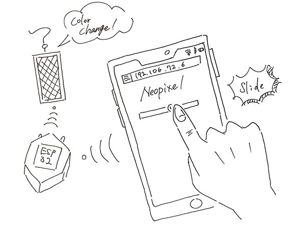
ESP32 Web Server Idea
First, I figured out how the mechanism would work to change the colors of the Neopixel from a mobile device, based on a sketch.
I decided to create an interface in html that could be operated by a mobile device and then build a program in Arduino to write it to the ESP32.
The interface will contain a slider from “0 to 4096”. This will allow you to adjust the color of the Neopiexl.
The value of the slider should be automatically updated without refreshing the web page.
That’s why we decided to use AJAX to send HTTP requests to ESP32 in the background.
Now refreshing the web page will not change the slider value, nor will it change the color of the Neopixel.
idea Sketch
Creating Html Code
① Creating a slider
To create a slider in HTML, use the <input> tag.
The <input> tag specifies the fields into which the user will enter data.
There are different types of input types. To define a slider, specify a value of “range” for the “type” attribute. In the slider, the “min” and “max” attributes must also be used to define a minimum and maximum range of values.
<input type="range" min="0" max="4096" class="slider" id="LEDSlider" onchange="led(this.value)" value=+ptmString+/>
Other attributes that need to be defined are as follows.
The class to style the slider.
An ID to update the current position displayed on the web page.
And finally, the onchange attribute for calling the servo function to send HTTP request to ESP32 when the slider is moved.
② Adding JavaScript to your HTML files
Next, we need to add the JavaScript code to the HTML file using the tags.
A snippet of this code will update the web page with the current slider position.
var slider = document.getElementById("LEDSlider");
var sliderP = document.getElementById("sliderPos");
sliderP.innerHTML = slider.value;
slider.oninput = function() {
  slider.value = this.value;
  sliderP.innerHTML = this.value;
}
Then, the following line makes an HTTP GET request for the IP address of ESP at this particular URL path.
$.ajaxSetup({timeout:1000});
function led(pos) {
  $.get("/?value=" + pos + "&");
  {Connection: close};
}
For example, if Neopixel’s position is 0, an HTTP GET request is made to the following URL.
http://your-esp-ip-address/?value=0&
And when the Neopixel reaches 4096 degrees, it looks like this
http://your-esp-ip-address/?value=4096&...
In this way, the ESP32 can retrieve the value parameter in the URL and move the Neopixel to the correct position when the GET request is received.
And I created the following code.
↓
html code
<!DOCTYPE html>
<html>
<head>
  <meta name= "viewport" content="width=device-width, initial-scale=1">
  <link rel="icon" href="data:,">
  <style>
    body {
      text-align: center;
      font-family: "Trebuchet MS", Arial;
      margin-left:auto;
      margin-right:auto;
    }
      .slider {
        width: 300px;
      }
    </style>
    <script src="https://ajax.googleapis.com/ajax/libs/jquery/3.3.1/jquery.min.js"></script>

  </head>
  <body>
    <h1>ESP32 with Neopixel</h1>
    <p>Position: <span id="sliderPos"></span></p>
    <input type="range" min="0" max="4096" class="slider" id="LEDSlider" onchange="led(this.value)" value=+ptmString+/>
    <script>
      var slider = document.getElementById("LEDSlider");
      var sliderP = document.getElementById("sliderPos");
      sliderP.innerHTML = slider.value;
      slider.oninput = function() {
        slider.value = this.value;
        sliderP.innerHTML = this.value;
      }
      $.ajaxSetup({timeout:1000});
      function led(pos) {
        $.get("/?value=" + pos + "&");
        {Connection: close};
      }
    </script>
  </body>
</html>
Embedding html code in the Arduino IDE
I need to make some changes to the html code we just created to control the ESP32.
① First Setting
The first thing we need to do is to include the <WiFi.h>.
We also need to insert your ssid and password in the following lines inside the double quotes.
And you set your web server to port [80].
The following line creates a variable to store the header of the HTTP request.
Then, create a couple of variables that will be used to extract the slider position from the HTTP request.
Finally, the following code defines the settings for HTTP requests.
It uses an [unsigned long] variable (capable of storing a 4-byte unsigned integer (0-2 to the 32nd power of 1) value) to measure the time that has elapsed since the program was started using the [millis function].
↓
#include <WiFi.h>

const char* ssid = "REPLACE_WITH_YOUR_SSID";
const char* password = "REPLACE_WITH_YOUR_PASSWORD";

WiFiServer server(80);

String header;

// Decode HTTP GET value
String valueString = String(5);
int pos1 = 0;
int pos2 = 0;

// Current time
unsigned long currentTime = millis();
// Previous time
unsigned long previousTime = 0;
// Define timeout time in milliseconds (example: 2000ms = 2s)
const long timeoutTime = 2000;
② setup( )
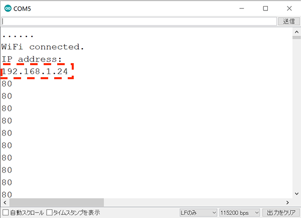
First, we start a serial communication at a baud rate of 115200 for debugging purposes.
The following lines begin the Wi-Fi connection with WiFi.begin(ssid, password), wait for a successful connection and print the ESP IP address in the Serial Monitor.
↓
Serial.begin(115200);
  // Connect to Wi-Fi network with SSID and password
  Serial.print("Connecting to ");
  Serial.println(ssid);
  WiFi.begin(ssid, password);
  while (WiFi.status() != WL_CONNECTED) {
    delay(500);
    Serial.print(".");
  }
  // Print local IP address and start web server
  Serial.println("");
  Serial.println("WiFi connected.");
  Serial.println("IP address: ");
  Serial.println(WiFi.localIP());
  server.begin();
③ loop( )
In the loop() I program what happens when a new client establishes a connection with the web server.
The ESP32 is always listening for incoming clients with the following line:
WiFiClient client = server.available(); // Listen for incoming clients
When a request is received from a client, we’ll save the incoming data.
The while loop that follows will be running as long as the client stays connected.
if (client) {                             // If a new client connects,
  currentTime = millis();
  previousTime = currentTime;
  Serial.println("New Client.");          // print a message out in the serial port
  String currentLine = "";                // make a String to hold incoming data from the client
  while (client.connected() && currentTime - previousTime <= timeoutTime) { // loop while the client's connected
    currentTime = millis();
    if (client.available()) {             // if there's bytes to read from the client,
      char c = client.read();             // read a byte, then
      Serial.write(c);                    // print it out the serial monitor
      header += c;
      if (c == '\n') {                    // if the byte is a newline character
        // if the current line is blank, you got two newline characters in a row.
        // that's the end of the client HTTP request, so send a response:
        if (currentLine.length() == 0) {
        // HTTP headers always start with a response code (e.g. HTTP/1.1 200 OK)
        // and a content-type so the client knows what's coming, then a blank line:
          client.println("HTTP/1.1 200 OK");
          client.println("Content-type:text/html");
          client.println("Connection: close");
          client.println();
④ Displaying the HTML web page
The next thing , I created the web page.
The ESP32 will be sending a response to your browser with some HTML code to build the web page.
The web page is sent to the client using this expressing [client.println()].
You should enter what you want to send to the client as an argument.
The first thing we should send is always the following line, that indicates that we are sending HTML.
client.println("<!DOCTYPE html><html>");
Then, the following line makes the web page responsive in any web browser.
And the following is used to prevent requests on the favicon. – You don’t need to worry about this line.
client.println("<head><meta name=\"viewport\" content=\"width=device-width, initial-scale=1\">");
client.println("<link rel=\"icon\" href=\"data:,\">");
⑤ Styling the Web Page
Then I used [client.println()] to rewrite the html code I just created.
client.println("<style>body { text-align: center; font-family: \"Trebuchet MS\", Arial; margin-left:auto; margin-right:auto;}");
client.println(".slider { width: 300px; }</style>");
client.println("<script src=\"https://ajax.googleapis.com/ajax/libs/jquery/3.3.1/jquery.min.js\"></script>");

// Web Page
client.println("</head><body><h1>ESP32 with Neopixel</h1>");
client.println("<p>Position: <span id=\"sliderPos\"></span></p>");
client.println("<input type=\"range\" min=\"0\" max=\"4096\" class=\"slider\" id=\"LEDSlider\" onchange=\"led(this.value)\" value=\""+ptmString+"\"/>");

client.println("<script>var slider = document.getElementById(\"LEDSlider\");");
client.println("var sliderP = document.getElementById(\"sliderPos\"); sliderP.innerHTML = slider.value;");
client.println("slider.oninput = function() { slider.value = this.value; sliderP.innerHTML = this.value; }");
client.println("$.ajaxSetup({timeout:1000}); function led(pos) { ");
client.println("$.get(\"/?value=\" + pos + \"&\"); {Connection: close};}</script>");

client.println("</body></html>");
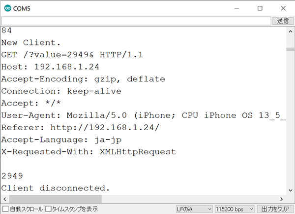
The following part of the code retrieves the slider value from the HTTP request.
//GET /?value=180& HTTP/1.1
if(header.indexOf("GET /?value=")>=0) {
  pos1 = header.indexOf('=');
  pos2 = header.indexOf('&');
  ptmString = header.substring(pos1+1, pos2);
Then the slider position value is saved in the valueString variable.
I have defined this variable as [ptmString].
Then, we set the servo to that specific position using Potmode() with the ptmString variable as an argument.
The ptmString variable is a string, so we need to use the toInt() method to convert it into an integer number.
//Rotate the servo
Potmode(ptmString.toInt());
Serial.println(ptmString);
}
Finally, I’ve included the string to be displayed on the serial monitor when the HTTP request fails.
// The HTTP response ends with another blank line
client.println();
// Break out of the while loop
break;
} else { // if you got a newline, then clear currentLine
currentLine = "";
}
} else if (c != '\r') {  // if you got anything else but a carriage return character,
currentLine += c;      // add it to the end of the currentLine
}
⑥ Closing the Connection
When the response ends, we clear the header variable, and stop the connection with the client with [client.stop()].
// Clear the header variable
header = "";
// Close the connection
client.stop();
Serial.println("Client disconnected.");
Serial.println("");
⑦ Combining with FinalProject’s code
I have merged the above code with the FinalProject code.
//******************************************************************//
//  ESP32  Send IR DATA automatically
//    2020.6.7
//    ESP32_IRsend06_1.ino
//     Send data = Sellect Table DATA by tapping accelerometer randomly
//     ADXL345(I2C) accelerometer
//******************************************************************//

//******************************************************************//
#include <WiFi.h>

// Replace with your network credentials
const char* ssid     = "fablabkamakura3_guest";
const char* password = "kamakura_1192";

// Set web server port number to 80
WiFiServer server(80);

// Variable to store the HTTP request
String header;

// Decode HTTP GET value
String ptmString = String(5);
int pos1 = 0;
int pos2 = 0;

// Current time
unsigned long currentTime = millis();
// Previous time
unsigned long previousTime = 0;
// Define timeout time in milliseconds (example: 2000ms = 2s)
const long timeoutTime = 2000;

const int rmtDataLength = 34;        // NEC format data length 34 bit
rmt_item32_t rmtData[rmtDataLength]; // data to send

const rmt_channel_t channel = RMT_CHANNEL_0;
const gpio_num_t irPin = GPIO_NUM_25;
//******************************************************************//

//****************************************//

const int leaderOnUs = 9000;
const int leaderOffUs = 4500;
const int dataOnUs = 560;
const int data1OffUs = 1690;
const int data0OffUs = 560;
const int stopbitOnUs = 560;
const int stopbitOffUs = 0x7fff;

//*************************************************************//
//   LED Brink Pattern Table definition
//*************************************************************//

/* LED pattern variable */
int LEDpatNo = 0; //LED pattern
int LEDpatCnt = 0; //LED data counter
int actionmode = 0;//インプットデバイスを使って色を変える
int singletap = 0;//setupでもloopの中でも使えるように
int Randomcounter = 0;//何回に一回ランダム表示を切り替えるか

/* Define 色 Code */
#define K0  0x80
#define K1  0x81
#define K2  0x82
#define K3  0x83
#define K4  0x84
#define K5  0x85
#define K6  0x86
#define K7  0x87

/* Define 明るさ Code */
#define B0  0x00
#define B1  0x40
#define B2  0x80
#define B3  0xC0

/* define LED pattern */
uint8_t LED0[] = { 1, K0 }; // ---
uint8_t LED1[] = { 1, K1 }; // --B
uint8_t LED2[] = { 1, K2 }; // -G-
uint8_t LED3[] = { 1, K3 }; // -GB
uint8_t LED4[] = { 1, K4 }; // R--
uint8_t LED5[] = { 1, K5 }; // R-B
uint8_t LED6[] = { 1, K6 }; // RG-
uint8_t LED7[] = { 1, K7 }; // RGB

uint8_t *LEDTBL[] = { LED0, LED1, LED2, LED3, LED4, LED5, LED6, LED7 };

//*** End of LED Brink Pattern Table definition ****************************//

#include <Wire.h>
#include "driver/rmt.h"

/* send NEC format remote control data */
void sendData(uint16_t customCode, uint8_t dataCode) {
  /* leader code 1bit: ON 9000us, OFF 4500us */
  rmtData[0].duration0 = leaderOnUs;
  rmtData[0].level0 = 1;
  rmtData[0].duration1 = leaderOffUs;
  rmtData[0].level1 = 0;

  /*
   * custom code 16 bit
   * INPUT series: b15 b14 b13 b12 b11 b10 b09 b08 b07 b06 b05 b04 b03 b02 b01 b00
   * SEND  series: b08 b09 b10 b11 b12 b13 b14 b15 b00 b01 b02 b03 b04 b05 b06 b07
   */
  for (int i = 0; i < 2; i++) {
    for (int j = 0; j < 8; j++) {
      /*
       * 1: ON 560us + OFF 1690us
       * 0: ON 560us + OFF  560us
      */
      rmtData[8 * i + j + 1].duration0 = dataOnUs;
      rmtData[8 * i + j + 1].level0 = 1;
      if (customCode & (1 << ((1 - i) * 8 + j))) {
        rmtData[8 * i + j + 1].duration1 = data1OffUs;
      } else {
        rmtData[8 * i + j + 1].duration1 = data0OffUs;
      }
      rmtData[8 * i + j + 1].level1 = 0;
    }
  }

  /*
   * data code 8bit
   * INPUT series: b7 b6 b5 b4 b3 b2 b1 b0
   * SEND  series: b0 b1 b2 b3 b4 b5 b6 b7 ~b0 ~b1 ~b2 ~b3 ~b4 ~b5 ~b6 ~b7
   */
  for (int i = 0; i < 8; i++) {
    rmtData[i + 17].duration0 = dataOnUs;
    rmtData[i + 25].duration0 = dataOnUs;
    rmtData[i + 17].level0 = 1;
    rmtData[i + 25].level0 = 1;
    if (dataCode & (1 << i)) {
      rmtData[i + 17].duration1 = data1OffUs;
      rmtData[i + 25].duration1 = data0OffUs;
    } else {
      rmtData[i + 17].duration1 = data0OffUs;
      rmtData[i + 25].duration1 = data1OffUs;
    }
    rmtData[i + 17].level1 = 0;
    rmtData[i + 25].level1 = 0;
  }

  /* stop bit 1bit: ON 560 */
  rmtData[33].duration0 = stopbitOnUs;
  rmtData[33].level0 = 1;
  rmtData[33].duration1 = stopbitOffUs;
  rmtData[33].level1 = 0;

  rmt_write_items(channel, rmtData, rmtDataLength, true);
}

//*************************************************//
//     Print 8bit data in HEX to console
//*************************************************//
void hexprint(uint8_t data){
  char HEXTBL[] = {'0', '1', '2', '3', '4', '5', '6', '7',
                   '8', '9', 'A', 'B', 'C', 'D', 'E', 'F' };
  Serial.print(HEXTBL[ (data & 0xF0) >> 4 ]);
  Serial.print(HEXTBL[ (data & 0x0F)]);
}

//*************************************************//
//      MAIN PROCESS
//*************************************************//

void setup() {

  rmt_config_t rmtConfig;
  rmtConfig.rmt_mode = RMT_MODE_TX;  // transmit mode
  rmtConfig.channel = channel;  // channel to use 0 - 7
  rmtConfig.clk_div = 80;  // clock divider 1 - 255. source clock is 80MHz -> 80MHz/80 = 1MHz -> 1 tick = 1 us
  rmtConfig.gpio_num = irPin; // pin to use
  rmtConfig.mem_block_num = 1; // memory block size

  rmtConfig.tx_config.loop_en = 0; // no loop
  rmtConfig.tx_config.carrier_freq_hz = 38000;  // IR remote controller uses 38kHz carrier frequency
  rmtConfig.tx_config.carrier_duty_percent = 33; // duty
  rmtConfig.tx_config.carrier_level =  RMT_CARRIER_LEVEL_HIGH; // carrier level
  rmtConfig.tx_config.carrier_en = 1;  // carrier enable
  rmtConfig.tx_config.idle_level =  RMT_IDLE_LEVEL_LOW ; // signal level at idle
  rmtConfig.tx_config.idle_output_en = 1;  // output if idle

  rmt_config(&rmtConfig);
  rmt_driver_install(rmtConfig.channel, 0, 0);

//******************************************************************//
  Serial.begin(115200);

  // Connect to Wi-Fi network with SSID and password
  Serial.print("Connecting to ");
  Serial.println(ssid);
  WiFi.begin(ssid, password);
  while (WiFi.status() != WL_CONNECTED) {
    delay(500);
    Serial.print(".");
  }
  // Print local IP address and start web server
  Serial.println("");
  Serial.println("WiFi connected.");
  Serial.println("IP address: ");
  Serial.println(WiFi.localIP());
  server.begin();
//******************************************************************//

}

void loop() {

//表示
/* Send LED data sequncially in the LED Pattern Table */
  uint8_t *p; // Define KeyPatternAddress pointer
  p = LEDTBL[LEDpatNo]; // Set pointer address
  int i = *p; // Get pattern length
  uint8_t kdata = *(p + LEDpatCnt + 1); // get Keydata
  sendData(0x00ff, kdata);
  hexprint(kdata);
  Serial.print(" ");
  LEDpatCnt++;
  if ( LEDpatCnt > i-1 ) {
    LEDpatCnt = 0;
    Serial.println();
  }
//  delay(30);

//******************************************************************//
  WiFiClient client = server.available();   // Listen for incoming clients

  if (client) {                             // If a new client connects,
    currentTime = millis();
    previousTime = currentTime;
    Serial.println("New Client.");          // print a message out in the serial port
    String currentLine = "";                // make a String to hold incoming data from the client
    while (client.connected() && currentTime - previousTime <= timeoutTime) { // loop while the client's connected
      currentTime = millis();
      if (client.available()) {             // if there's bytes to read from the client,
        char c = client.read();             // read a byte, then
        Serial.write(c);                    // print it out the serial monitor
        header += c;
        if (c == '\n') {                    // if the byte is a newline character
          // if the current line is blank, you got two newline characters in a row.
          // that's the end of the client HTTP request, so send a response:
          if (currentLine.length() == 0) {
            // HTTP headers always start with a response code (e.g. HTTP/1.1 200 OK)
            // and a content-type so the client knows what's coming, then a blank line:
            client.println("HTTP/1.1 200 OK");
            client.println("Content-type:text/html");
            client.println("Connection: close");
            client.println();

            // Display the HTML web page
            client.println("<!DOCTYPE html><html>");
            client.println("<head><meta name=\"viewport\" content=\"width=device-width, initial-scale=1\">");
            client.println("<link rel=\"icon\" href=\"data:,\">");

            client.println("<style>body { text-align: center; font-family: \"Trebuchet MS\", Arial; margin-left:auto; margin-right:auto;}");
            client.println(".slider { width: 300px; }</style>");
            client.println("<script src=\"https://ajax.googleapis.com/ajax/libs/jquery/3.3.1/jquery.min.js\"></script>");

            // Web Page
            client.println("</head><body><h1>ESP32 with Neopixel</h1>");
            client.println("<p>Position: <span id=\"sliderPos\"></span></p>");
            client.println("<input type=\"range\" min=\"0\" max=\"4096\" class=\"slider\" id=\"LEDSlider\" onchange=\"led(this.value)\" value=\""+ptmString+"\"/>");

            client.println("<script>var slider = document.getElementById(\"LEDSlider\");");
            client.println("var sliderP = document.getElementById(\"sliderPos\"); sliderP.innerHTML = slider.value;");
            client.println("slider.oninput = function() { slider.value = this.value; sliderP.innerHTML = this.value; }");
            client.println("$.ajaxSetup({timeout:1000}); function led(pos) { ");
            client.println("$.get(\"/?value=\" + pos + \"&\"); {Connection: close};}</script>");

            client.println("</body></html>");

            //GET /?value=180& HTTP/1.1
            if(header.indexOf("GET /?value=")>=0) {
              pos1 = header.indexOf('=');
              pos2 = header.indexOf('&');
              ptmString = header.substring(pos1+1, pos2);

              //Rotate the servo
              Potmode(ptmString.toInt());
              Serial.println(ptmString);
            }
            // The HTTP response ends with another blank line
            client.println();
            // Break out of the while loop
            break;
          } else { // if you got a newline, then clear currentLine
            currentLine = "";
          }
        } else if (c != '\r') {  // if you got anything else but a carriage return character,
          currentLine += c;      // add it to the end of the currentLine
        }
      }
    }
    // Clear the header variable
    header = "";
    // Close the connection
    client.stop();
    Serial.println("Client disconnected.");
    Serial.println("");
  }
//******************************************************************//

}

void Potmode(int analogdata1){  //ポテンショメータで制御するプログラム
  if(analogdata1<500){
    LEDpatNo = 0;
  }
  else if(analogdata1<1000){
    LEDpatNo = 1;
  }
  else if(analogdata1<1500){
    LEDpatNo = 2;
  }
  else if(analogdata1<2000){
    LEDpatNo = 3;
  }
  else if(analogdata1<2500){
    LEDpatNo = 4;
  }
  else if(analogdata1<3000){
    LEDpatNo = 5;
  }
  else if(analogdata1<3500){
    LEDpatNo = 6;
  }
  else{
    LEDpatNo = 7;
  }

  LEDpatCnt = 0;
}
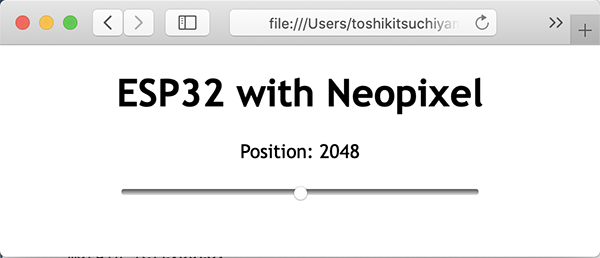
Testing the Web Server
I have uploaded the above code to the ESP32.
Open the serial monitor with a baud rate of 115200 and copy the ESP32 IP address that appears on the serial monitor to the window on the mobile device.
The web page I created appears and when I move the slide, the color of the Neopixel changes.
↓
5. Description of Important Weekly Learning Outcome
The ESP32 is suitable for [IoT], where you can connect sensors and various devices to take advantage of it. It wasn’t too difficult to connect a sensor to a GPIO port to read sensor values or connect a motor to run it. But trying to control this from the Internet would require building a server-side program or designing a smartphone app. I think [Blynk] is so much better than other [IoT] services in that you can use some of these programs for free. It’s also easy to understand the virtual device programs that come standard, so I was able to combine them with my own programs to build a new system.