- Presentation Preparation
1. Weekly Brief Summary
This week I took photos and videos of the accessories I made and created slides and a promotional video for the presentation.
I used Adobe Illustrator to create the slides and iMovie to edit the video.
I had the help of Yuzuki Nagase as a model and Rico, an instructor at FabLab Kamakura, as a cameraman.
2. Description of Final Proect Work
Preparation for shooting
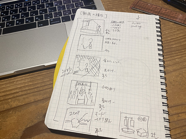
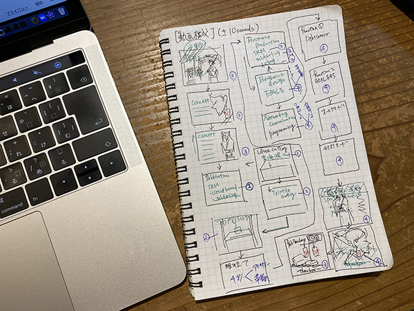
I came up with a storyboard format of what kind of picture I wanted before the shoot.
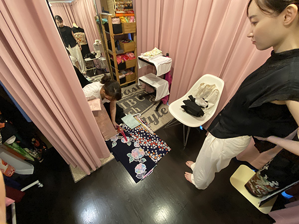
This time I went to a kimono/yukata rental shop near the lab and asked for a model’s dressing and heya style set. I went over which fabric design to use for the obidome in advance at the shop.


It took me about 15 minutes to set the hairy style. This time I had my earrings done in a hairy style that would look great on the screen.


The dressing process takes about 40 minutes, so I rented a Japanese umbrella from another rental shop while I was there.
Rental Japanese umbrella

Program Modifications
I created a new program before the shoot began. It has two lighting modes: [a lighting pattern that matches the pattern of the kimono (the design of the aurora borealis)] and [a pattern that glows like a lantern]. (The two lighting patterns are described in [Ahhh].) I added more color codes to the ATtiny85 of the earring and wrote the lighting pattern program to the ESP32 of the obi clip, respectively.
Earring side
//-------------------------------------------------------------------------------------------------------------------------
/*
 *  IrDA receive data print program
 *    IRreceive_print01.ino
 *      2020.5.28

 * Original Scketch
   ATtiny85 IR Remote Control Receiver
   David Johnson-Davies - www.technoblogy.com - 3rd April 2015
   ATtiny85 @ 1 MHz (internal oscillator; BOD disabled)
   CC BY 4.0
   Licensed under a Creative Commons Attribution 4.0 International license:
   http://creativecommons.org/licenses/by/4.0/
*/

//#include <SoftwareSerial.h>
//SoftwareSerial mySerial(3, 4); RX(PB3:Pin2), TX(PB4:Pin3)

// LED outputs
int LED = 1;   // LED indicator PB1(Pin6)

volatile int NextBit;
volatile unsigned long RecdData;
volatile int Rcvflag = 0;
volatile int RcvDATA;

char HEXprint[] = {'0','1','2','3','4','5','6','7','8','9','A','B','C','D','E','F'} ;

#include <Adafruit_NeoPixel.h>
#ifdef __AVR__
#include <avr/power.h>
#endif

#define PIN 1

// Parameter 1 = number of pixels in strip
// Parameter 2 = Arduino pin number (most are valid)
// Parameter 3 = pixel type flags, add together as needed:
//   NEO_KHZ800  800 KHz bitstream (most NeoPixel products w/WS2812 LEDs)
//   NEO_KHZ400  400 KHz (classic 'v1' (not v2) FLORA pixels, WS2811 drivers)
//   NEO_GRB     Pixels are wired for GRB bitstream (most NeoPixel products)
//   NEO_RGB     Pixels are wired for RGB bitstream (v1 FLORA pixels, not v2)
//   NEO_RGBW    Pixels are wired for RGBW bitstream (NeoPixel RGBW products)
Adafruit_NeoPixel strip = Adafruit_NeoPixel(1, PIN, NEO_GRB + NEO_KHZ800);

// IMPORTANT: To reduce NeoPixel burnout risk, add 1000 uF capacitor across
// pixel power leads, add 300 - 500 Ohm resistor on first pixel's data input
// and minimize distance between Arduino and first pixel.  Avoid connecting
// on a live circuit...if you must, connect GND first.

// Setup **********************************************

void setup() {
  // Set up LEDs
  pinMode(LED, OUTPUT);

  // initialize Serial Port
  //mySerial.begin(9600);
  //delay(500);
  //mySerial.println("Serial connect");

  // Set up Timer/Counter0 (assumes 8MHz clock)
  TCCR0A = 0;                 // No compare matches
  TCCR0B = 5<<CS00;           // Prescaler /64
  // Set up INT0 interrupt on PB2
  MCUCR = MCUCR | 2<<ISC00;   // Interrupt on falling edge
  GIMSK = GIMSK | 1<<INT0;    // Enable INT0
  NextBit = 32;               // Wait for AGC start pulse

  // This is for Trinket 5V 16MHz, you can remove these three lines if you are not using a Trinket
  #if defined (__AVR_ATtiny85__)
    if (F_CPU == 16000000) clock_prescale_set(clock_div_1);
  #endif
  // End of trinket special code

  strip.begin();
  strip.setBrightness(50);
  strip.show(); // Initialize all pixels to 'off'


}

void loop() {
  if (Rcvflag != 0){
    Rcvflag = 0;
    //char Pdata = (RcvDATA & 0xF0)>>4 ; // pickup upper 4 bits
    //mySerial.print(HEXprint[Pdata]);   // print in HEX
    //Pdata = (RcvDATA & 0x0F);          // pickup lower 4 bits
    //mySerial.println(HEXprint[Pdata]); // print in HEX
//ATtiny85でしか色の設定は出てこない→自分で作った色テーブルを用意する
    uint32_t c[64] = {0x000000,0xFF0000, //{0(消灯),1(赤)
                      0xFF6600,0xFFFF00, //2(橙),3(黄)
                      0x00FF00,0x0000FF, //4(緑),5(青)
                      0x000080,0x800080, //6(紺),7(紫)
                      0x99FFFF,0x99CCFF, //8,9
                      0x9999FF,0x9966FF, //10,11
                      0x9933FF,0x9900FF, //12,13
                      0xFFFF00,0xFFCC00, //14,15
                      0xFF9900,0xFF6600, //16,17
                      0xFF3300}; //18

    int cl = (RcvDATA & 0x3F);
    int b;
    b = (RcvDATA & 0xC0)>>6;
    int br[4] = {10,30,60,100};
    strip.setBrightness(br[b]);
    colorWipe(c[cl],0);
}
}

// *** Interrupt service routine - called on every falling edge of PB2 ***

ISR(INT0_vect) {
  int Time = TCNT0;
  int Overflow = TIFR & 1<<TOV0;
  // Keep looking for AGC pulse and gap
  if (NextBit == 32) {
    if ((Time >= 87) && (Time <= 114) && (Overflow == 0)) {
      RecdData = 0; NextBit = 0;
    } else if ((Time >= 80) && (Time <= 97) && (Overflow == 0)) ReceivedCode(1);
  // Data bit
  } else {
    if ((Time > 22) || (Overflow != 0)) NextBit = 32; // Invalid - restart
    else {
      if (Time > 13) RecdData = RecdData | ((unsigned long) 1<<NextBit);
      if (NextBit == 31) ReceivedCode(0);
      NextBit++;
    }
  }
  TCNT0 = 0;                  // Clear counter
  TIFR = TIFR | 1<<TOV0;      // Clear overflow
  GIFR = GIFR | 1<<INTF0;     // Clear INT0 flag
}

// Main Process after IrDA data received
void ReceivedCode(boolean Repeat) {
  // Check for correct remote control
  if ((RecdData & 0xFFFF) != 0xff00) return; // check the maker_code 0xFF
  // Read key pressed
  RcvDATA = RecdData>>16 & 0xFF;

  // Set DATA receivedflag for SerialPrint
  Rcvflag = 1;

}

//colorWipe(c,0);
void colorWipe(uint32_t c, uint8_t wait) {
  for(uint16_t i=0; i<strip.numPixels(); i++) {
      strip.setPixelColor(i, c);
      strip.show();
      delay(wait);
  }
}
Obi clasp side
//******************************************************************//
//  ESP32  Send IR DATA automatically
//    2020.6.7
//    ESP32_IRsend06_1.ino
//     Send data = Sellect Table DATA by tapping accelerometer randomly
//     ADXL345(I2C) accelerometer
//******************************************************************//

#include "driver/rmt.h"

const int rmtDataLength = 34;        // NEC format data length 34 bit
rmt_item32_t rmtData[rmtDataLength]; // data to send

const rmt_channel_t channel = RMT_CHANNEL_0;
const gpio_num_t irPin = GPIO_NUM_25;

//****************************************//
const gpio_num_t PTMPin = GPIO_NUM_32; // Potentiometer input
const gpio_num_t AMBPin = GPIO_NUM_33; // Ambient senser
const gpio_num_t MICPin = GPIO_NUM_34; // Audio senser
//****************************************//

const int leaderOnUs = 9000;
const int leaderOffUs = 4500;
const int dataOnUs = 560;
const int data1OffUs = 1690;
const int data0OffUs = 560;
const int stopbitOnUs = 560;
const int stopbitOffUs = 0x7fff;

//*************************************************************//
//   LED Brink Pattern Table definition
//*************************************************************//

/* LED pattern variable */
int LEDpatNo = 0; //LED pattern
int LEDpatCnt = 0; //LED data counter
int actionmode = 0;//インプットデバイスを使って色を変える
int singletap = 0;//setupでもloopの中でも使えるように
int Randomcounter = 0;//何回に一回ランダム表示を切り替えるか

/* Define 色 Code */
#define K0  0x80
#define K1  0x81
#define K2  0x82
#define K3  0x83
#define K4  0x84
#define K5  0x85
#define K6  0x86
#define K7  0x87
#define K8  0x08
#define K9  0x09
#define K10  0x0A
#define K11  0x0B
#define K12  0x0C
#define K13  0x0D
#define K14  0x0E
#define K15  0x0F
#define K16  0x10
#define K17  0x11
#define K18  0x12
#define K19  0x13
#define K20  0x14

/* Define 明るさ Code */
#define B0  0x00
#define B1  0x40
#define B2  0x80
#define B3  0xC0


/* define LED pattern */
uint8_t LED0[] = { 1, K0 }; // ---
uint8_t LED1[] = { 1, K1 }; // --B
uint8_t LED2[] = { 1, K2 }; // -G-
uint8_t LED3[] = { 1, K3 }; // -GB
uint8_t LED4[] = { 1, K4 }; // R--
uint8_t LED5[] = { 1, K5 }; // R-B
uint8_t LED6[] = { 1, K6 }; // RG-
uint8_t LED7[] = { 1, K7 }; // RGB

uint8_t LED8[] = { 4, K4, K0, K4, K0 }; //
uint8_t LED9[] = { 4, K4, K2, K1, K0 }; //
uint8_t LED10[] = { 7, K2, K2, K2, K0, K2, K2, K0 }; //
uint8_t LED11[] = { 8, K4, K4, K0, K2, K2, K0, K1, K1, K0 }; //
uint8_t LED12[] = { 7, K1, K2, K3, K4, K5, K6, K7 }; //
uint8_t LED13[] = { 14, K1, K1, K2, K2, K3, K3, K4, K4, K5, K5, K6, K6, K7, K7 }; //
uint8_t LED14[] = { 6, K4, K0, K4, K0, K0, K0 }; //
uint8_t LED15[] = { 16, K4, K2, K1, K0, K4, K2, K1, K0, K4, K0, K2, K0, K6, K0, K0 }; // Pattern15

uint8_t LED16[] = { 1, B2+K8 };
uint8_t LED17[] = { 1, B2+K9 };
uint8_t LED18[] = { 1, B2+K10 };
uint8_t LED19[] = { 1, B2+K11 };
uint8_t LED20[] = { 1, B2+K12 };
uint8_t LED21[] = { 1, B2+K13 };

uint8_t LED22[] = { 1, B0+K14 };
uint8_t LED23[] = { 1, B1+K14 };
uint8_t LED24[] = { 1, B2+K14 };
uint8_t LED25[] = { 1, B0+K15 };
uint8_t LED26[] = { 1, B1+K15 };
uint8_t LED27[] = { 1, B2+K15 };
uint8_t LED28[] = { 1, B0+K16 };
uint8_t LED29[] = { 1, B1+K16 };
uint8_t LED30[] = { 1, B2+K16 };
uint8_t LED31[] = { 1, B0+K17 };
uint8_t LED32[] = { 1, B1+K17 };
uint8_t LED33[] = { 1, B2+K17 };
uint8_t LED34[] = { 1, B0+K18 };
uint8_t LED35[] = { 1, B1+K18 };
uint8_t LED36[] = { 1, B2+K18 };

uint8_t *LEDTBL[] = { LED0, LED1, LED2, LED3, LED4, LED5, LED6, LED7, LED8, LED9, LED10, LED11, LED12, LED13, LED14, LED15, LED16, LED17,
LED18, LED19, LED20, LED21, LED22, LED23, LED24, LED25,LED26, LED27, LED28,LED29, LED30, LED31,LED32, LED33,LED34, LED35,LED36};

//*** End of LED Brink Pattern Table definition ****************************//

//***** Accelerometer *****
#include <Wire.h>
#include <ADXL345.h>

ADXL345 adxl;

/* send NEC format remote control data */
void sendData(uint16_t customCode, uint8_t dataCode) {
  /* leader code 1bit: ON 9000us, OFF 4500us */
  rmtData[0].duration0 = leaderOnUs;
  rmtData[0].level0 = 1;
  rmtData[0].duration1 = leaderOffUs;
  rmtData[0].level1 = 0;

  /*
   * custom code 16 bit
   * INPUT series: b15 b14 b13 b12 b11 b10 b09 b08 b07 b06 b05 b04 b03 b02 b01 b00
   * SEND  series: b08 b09 b10 b11 b12 b13 b14 b15 b00 b01 b02 b03 b04 b05 b06 b07
   */
  for (int i = 0; i < 2; i++) {
    for (int j = 0; j < 8; j++) {
      /*
       * 1: ON 560us + OFF 1690us
       * 0: ON 560us + OFF  560us
      */
      rmtData[8 * i + j + 1].duration0 = dataOnUs;
      rmtData[8 * i + j + 1].level0 = 1;
      if (customCode & (1 << ((1 - i) * 8 + j))) {
        rmtData[8 * i + j + 1].duration1 = data1OffUs;
      } else {
        rmtData[8 * i + j + 1].duration1 = data0OffUs;
      }
      rmtData[8 * i + j + 1].level1 = 0;
    }
  }

  /*
   * data code 8bit
   * INPUT series: b7 b6 b5 b4 b3 b2 b1 b0
   * SEND  series: b0 b1 b2 b3 b4 b5 b6 b7 ~b0 ~b1 ~b2 ~b3 ~b4 ~b5 ~b6 ~b7
   */
  for (int i = 0; i < 8; i++) {
    rmtData[i + 17].duration0 = dataOnUs;
    rmtData[i + 25].duration0 = dataOnUs;
    rmtData[i + 17].level0 = 1;
    rmtData[i + 25].level0 = 1;
    if (dataCode & (1 << i)) {
      rmtData[i + 17].duration1 = data1OffUs;
      rmtData[i + 25].duration1 = data0OffUs;
    } else {
      rmtData[i + 17].duration1 = data0OffUs;
      rmtData[i + 25].duration1 = data1OffUs;
    }
    rmtData[i + 17].level1 = 0;
    rmtData[i + 25].level1 = 0;
  }

  /* stop bit 1bit: ON 560 */
  rmtData[33].duration0 = stopbitOnUs;
  rmtData[33].level0 = 1;
  rmtData[33].duration1 = stopbitOffUs;
  rmtData[33].level1 = 0;

  rmt_write_items(channel, rmtData, rmtDataLength, true);
}

//*************************************************//
//     Print 8bit data in HEX to console
//*************************************************//
void hexprint(uint8_t data){
  char HEXTBL[] = {'0', '1', '2', '3', '4', '5', '6', '7',
                   '8', '9', 'A', 'B', 'C', 'D', 'E', 'F' };
  Serial.print(HEXTBL[ (data & 0xF0) >> 4 ]);
  Serial.print(HEXTBL[ (data & 0x0F)]);
}

//*************************************************//
//      MAIN PROCESS
//*************************************************//

void setup() {

  rmt_config_t rmtConfig;
  rmtConfig.rmt_mode = RMT_MODE_TX;  // transmit mode
  rmtConfig.channel = channel;  // channel to use 0 - 7
  rmtConfig.clk_div = 80;  // clock divider 1 - 255. source clock is 80MHz -> 80MHz/80 = 1MHz -> 1 tick = 1 us
  rmtConfig.gpio_num = irPin; // pin to use
  rmtConfig.mem_block_num = 1; // memory block size

  rmtConfig.tx_config.loop_en = 0; // no loop
  rmtConfig.tx_config.carrier_freq_hz = 38000;  // IR remote controller uses 38kHz carrier frequency
  rmtConfig.tx_config.carrier_duty_percent = 33; // duty
  rmtConfig.tx_config.carrier_level =  RMT_CARRIER_LEVEL_HIGH; // carrier level
  rmtConfig.tx_config.carrier_en = 1;  // carrier enable
  rmtConfig.tx_config.idle_level =  RMT_IDLE_LEVEL_LOW ; // signal level at idle
  rmtConfig.tx_config.idle_output_en = 1;  // output if idle

  rmt_config(&rmtConfig);
  rmt_driver_install(rmtConfig.channel, 0, 0);

  Serial.begin(115200);
  pinMode( PTMPin, INPUT );
  pinMode( AMBPin, INPUT );
  pinMode( MICPin, INPUT );

  adxl.powerOn();

  //set activity/ inactivity thresholds (0-255)
  adxl.setActivityThreshold(75); //62.5mg per increment
  adxl.setInactivityThreshold(75); //62.5mg per increment
  adxl.setTimeInactivity(10); // how many seconds of no activity is inactive?

  //look of activity movement on this axes - 1 == on; 0 == off
  adxl.setActivityX(1);
  adxl.setActivityY(1);
  adxl.setActivityZ(1);

  //look of inactivity movement on this axes - 1 == on; 0 == off
  adxl.setInactivityX(1);
  adxl.setInactivityY(1);
  adxl.setInactivityZ(1);

  //look of tap movement on this axes - 1 == on; 0 == off
  adxl.setTapDetectionOnX(0);
  adxl.setTapDetectionOnY(0);
  adxl.setTapDetectionOnZ(1);

  //set values for what is a tap, and what is a double tap (0-255)
  adxl.setTapThreshold(50); //62.5mg per increment
  adxl.setTapDuration(15); //625μs per increment
  adxl.setDoubleTapLatency(80); //1.25ms per increment
  adxl.setDoubleTapWindow(200); //1.25ms per increment

  //set values for what is considered freefall (0-255)
  adxl.setFreeFallThreshold(7); //(5 - 9) recommended - 62.5mg per increment
  adxl.setFreeFallDuration(45); //(20 - 70) recommended - 5ms per increment

  //setting all interupts to take place on int pin 1
  //I had issues with int pin 2, was unable to reset it
  adxl.setInterruptMapping( ADXL345_INT_SINGLE_TAP_BIT,   ADXL345_INT1_PIN );
  adxl.setInterruptMapping( ADXL345_INT_DOUBLE_TAP_BIT,   ADXL345_INT1_PIN );
  adxl.setInterruptMapping( ADXL345_INT_FREE_FALL_BIT,    ADXL345_INT1_PIN );
  adxl.setInterruptMapping( ADXL345_INT_ACTIVITY_BIT,     ADXL345_INT1_PIN );
  adxl.setInterruptMapping( ADXL345_INT_INACTIVITY_BIT,   ADXL345_INT1_PIN );

  //register interupt actions - 1 == on; 0 == off
  adxl.setInterrupt( ADXL345_INT_SINGLE_TAP_BIT, 1);
  adxl.setInterrupt( ADXL345_INT_DOUBLE_TAP_BIT, 1);
  adxl.setInterrupt( ADXL345_INT_FREE_FALL_BIT,  1);
  adxl.setInterrupt( ADXL345_INT_ACTIVITY_BIT,   1);
  adxl.setInterrupt( ADXL345_INT_INACTIVITY_BIT, 1);

  /* initialize variables */
  LEDpatNo = 0;
  LEDpatCnt = 0;
}

void loop() {
  //光と音の検出
  int amb = analogRead(AMBPin);
  int mic = analogRead(MICPin);
  int ptm = analogRead(PTMPin);

//加速度センサーの検出
  //Boring accelerometer stuff
  //int x,y,z;
  //adxl.readXYZ(&x, &y, &z); //read the accelerometer values and store them in variables  x,y,z

  // Output x,y,z values - Commented out
  //Serial.print(x);
  //Serial.print(y);
  //Serial.println(z);

  //read interrupts source and look for triggerd actions

  //getInterruptSource clears all triggered actions after returning value
  //so do not call again until you need to recheck for triggered actions
   byte interrupts = adxl.getInterruptSource();

  // freefall
  //if(adxl.triggered(interrupts, ADXL345_FREE_FALL)){
    //Serial.println("Free-fall detected.");           //自由落下を検出しました。
    //add code here to do when freefall is sensed
  //}

  //inactivity
  //if(adxl.triggered(interrupts, ADXL345_INACTIVITY)){
    //Serial.println("No motion detected.");          //動きを検出しなかった。
     //add code here to do when inactivity is sensed
  //}

  //activity
  //if(adxl.triggered(interrupts, ADXL345_ACTIVITY)){
    //Serial.println("Motion detected.");                 //動きを検出しました。
//    LEDpatNo = random( 0, 7 );
//    LEDpatCnt = 0;
  //}

  //double tap
  if(adxl.triggered(interrupts, ADXL345_DOUBLE_TAP)){
    Serial.println("Double tap detected.");           //ダブルタップを検出しました。
    actionmode = actionmode+1;
    if(actionmode>7){//ここを4から5に変えないとRam2までいかなかった
      actionmode = 0;//ダブルタップをしたらアクションモードが1つずつ変わる
    }
    LEDpatCnt = 0;//テーブルが変わってもいいようにしておく
  }

/*
  //tap
  if(adxl.triggered(interrupts, ADXL345_SINGLE_TAP)){
    Serial.println("Single tap detected.");            //シングルタップを検出しました。
    LEDpatNo = random( 8, 15 );
    LEDpatCnt = 0;
  }
*/

  //tap
  if(adxl.triggered(interrupts, ADXL345_SINGLE_TAP) && !adxl.triggered(interrupts, ADXL345_DOUBLE_TAP)){
    Serial.println("Single tap detected.");            //シングルタップを検出しました。
    singletap = 1;//シングルタップされたことを記憶するだけ
    LEDpatCnt = 0;
  }

  //actionmodeを切り替える
  switch(actionmode){
    case 0:
      Ambmode(amb);
      break;

    case 1:
      Micmode(mic);
      break;

    case 2:
      Tapmode();
      break;

    case 3:
      Potmode(ptm);
      break;

    case 4:
      Ram1mode();
      break;

    case 5:
      Ram2mode();
      break;

    case 6:
      And1mode();
      break;

    case 7:
      And2mode();
      break;

  }

//表示
/* Send LED data sequncially in the LED Pattern Table */
  uint8_t *p; // Define KeyPatternAddress pointer
  p = LEDTBL[LEDpatNo]; // Set pointer address
  int i = *p; // Get pattern length
  uint8_t kdata = *(p + LEDpatCnt + 1); // get Keydata
  sendData(0x00ff, kdata);
  hexprint(kdata);
  Serial.print(" ");
  LEDpatCnt++;
  if ( LEDpatCnt > i-1 ) {
    LEDpatCnt = 0;
    Serial.println();
  }
//  delay(30);
}

void Micmode(int analogdata3){  //音センサーで制御するプログラム
  if(analogdata3<500){
    LEDpatNo = 0;
  }
  else if(analogdata3<1000){
    LEDpatNo = 1;
  }
  else if(analogdata3<1500){
    LEDpatNo = 2;
  }
  else if(analogdata3<2000){
    LEDpatNo = 3;
  }
  else if(analogdata3<2500){
    LEDpatNo = 4;
  }
  else if(analogdata3<3000){
    LEDpatNo = 5;
  }
  else if(analogdata3<3500){
    LEDpatNo = 6;
  }
  else{
    LEDpatNo = 7;
  }

  LEDpatCnt = 0;
}

void Ambmode(int analogdata2){  //光センサーで制御するプログラム
  if(analogdata2<500){
    LEDpatNo = 0;
  }
  else if(analogdata2<1000){
    LEDpatNo = 1;
  }
  else if(analogdata2<1500){
    LEDpatNo = 2;
  }
  else if(analogdata2<2000){
    LEDpatNo = 3;
  }
  else if(analogdata2<2500){
    LEDpatNo = 4;
  }
  else if(analogdata2<3000){
    LEDpatNo = 5;
  }
  else if(analogdata2<3500){
    LEDpatNo = 6;
  }
  else{
    LEDpatNo = 7;
  }

  LEDpatCnt = 0;
}

void Potmode(int analogdata1){  //ポテンショメータで制御するプログラム
  if(analogdata1<500){
    LEDpatNo = 0;
  }
  else if(analogdata1<1000){
    LEDpatNo = 1;
  }
  else if(analogdata1<1500){
    LEDpatNo = 2;
  }
  else if(analogdata1<2000){
    LEDpatNo = 3;
  }
  else if(analogdata1<2500){
    LEDpatNo = 4;
  }
  else if(analogdata1<3000){
    LEDpatNo = 5;
  }
  else if(analogdata1<3500){
    LEDpatNo = 6;
  }
  else{
    LEDpatNo = 7;
  }

  LEDpatCnt = 0;
}

void Tapmode(){
  if(singletap = 1){
    LEDpatNo = random(8,16);
    singletap = 0;
    LEDpatCnt = 0;
  }
}
void Ram1mode(){
  LEDpatNo = random(0,8);
  LEDpatCnt = 0;
}

void Ram2mode(){
  Randomcounter++;
  if(Randomcounter>20){//約2秒に1回パターンが変わる
    LEDpatNo = random(8,16);
    LEDpatCnt = 0;
    Randomcounter = 0;
  }
}

void And1mode(){
  Randomcounter++;
  if(Randomcounter>3){
  LEDpatNo = random(16,22);
  LEDpatCnt = 0;
  Randomcounter = 0;
  }
}

void And2mode(){
  Randomcounter++;
  if(Randomcounter>1){
  LEDpatNo = random(22,37);
  LEDpatCnt = 0;
  Randomcounter = 0;
  }
}
Start shooting
The filming was done in the vicinity of FabLab Kamakura.
In front of Koga’s house (古我邸)
The Koga’s house (古我邸) is one of the three largest Western-style buildings in Kamakura with a history of 100 years and is now a French restaurant. We took photos in front of this garden and in the alleyways around it.


In front of Yui’s house (結の蔵)
This building is where FabLab Kamakura is located. It was originally a 100 year old wooden sake brewery that was relocated and built in another location. It has become a famous tourist attraction here.


FabLab Kamakura
Next, we filmed inside FabLab Kamakura.

Phototransistor mode
When the room is bright, the earrings do not glow, and when the room is dark, the earrings glow.
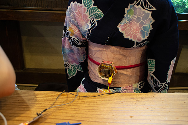
Switching between lighting modes
You can switch the lighting mode by tapping twice on the obi-dome.
A view of the lighting pattern for the lantern version
This time I created a pattern with a glow-in-the-dark pattern using the earring motif.
End of shooting
It took about three hours to shoot, but the team did a great job making the footage look great.
Special Thanks
- Model・・・Yuzuki Nagase
- Cameraman・・・Rico

Video Editing
I created a storyboard before I edited the video. Based on this storyboard, I combined the footage and photos I had taken and edited a one-minute video.
The editing software I used was [iMovie]. If you are an Apple user, you can use it for free as it’s already installed in your Macbook.

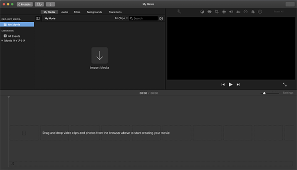
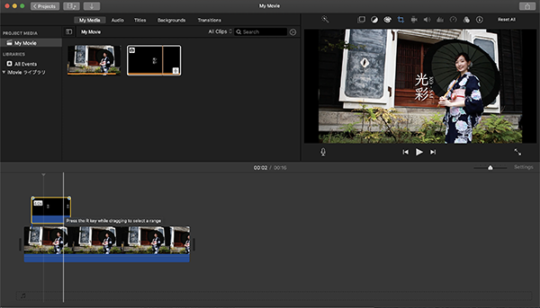
Uploading Videos
I clicked [Import Media] in the upper left corner of the screen and loaded the video.
↓
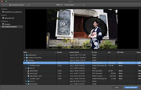
Select a video to load and click “Import Selected”.
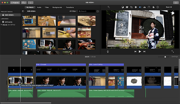
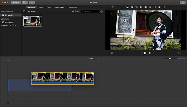
Once the video appeared on imovie as shown in the picture above, I dragged the video to the bottom and edited, trimmed, and otherwise processed the video.
Trimming Video
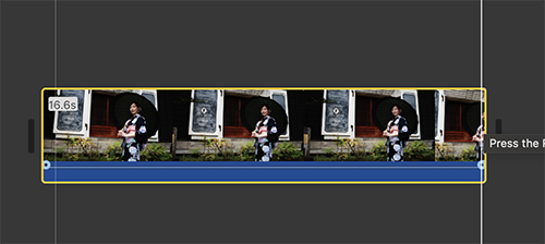
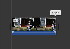
When you click the video you just dragged to the bottom, a yellow frame will appear. Then I trimmed the video by moving the frame to the part I wanted to delete while clicking the yellow border.
↓
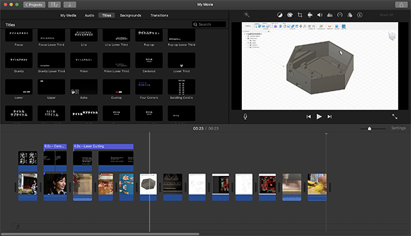
Inserting the Title
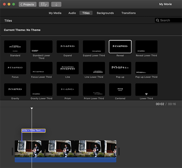
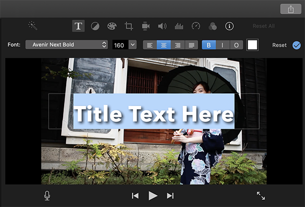
When I clicked on the Title tab at the top, a list of text materials was displayed, so I chose a design of my choice. I dragged the selected material to the top of the video where I wanted to insert the title and entered the text.
I used the edit screen on the right for the text.
Inserting text
I tried to display text to explain the content of the video separately from the title, but I couldn’t freely write any text other than the title. So I used [Adobe Illustrator] to export the text explaining the content of the video as [PNG] data and added it to the top surface.
↓
I imported the exported [PNG] file from [Import Media] in the same way as before and dragged it to the top part of the video where I wanted to insert it. I added other videos and text in this way.
↓
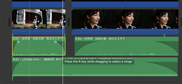
Inserting BGM
I clicked “Import Media” as I did with the video and loaded the background music I wanted to insert. To link an audio file to a specific video clip and maintain that relationship as you move it around, drag the audio file right underneath the video clip so that the vertical line connecting both clips is visible. You can also fade in and out of the background music by moving the small left and right round marks that appear when you move your mouse over a music file.
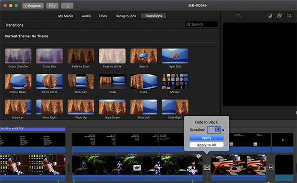
Inserting the transitional effect
I inserted a [Transition Effect] as an effect when the screen changes in the video. You can see a list of [Transitions] by clicking the [Transitions] tab. We inserted the effect by dragging it to the place where we want to add it, in the same way as before. By double-clicking the [Transitions] icon, you can set the duration of the effect.
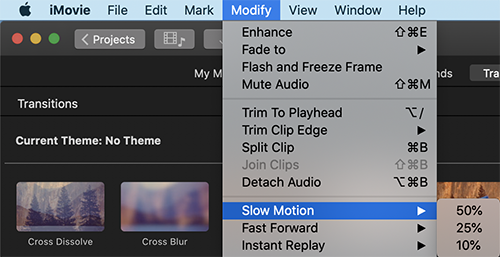
Slow Motion Playback Settings
I wanted to adjust the timing of the video and BGM for the end roll, so I adjusted the playback speed. For slow motion function, select a clip and click [Modify] -> [Slow Motion] to apply slow motion. At first, you can only choose the speed from [50%], [25%] and [10%], but you can change it freely afterwards.
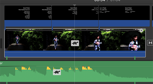
To change the playback speed later, click the [Turtle] icon above the video clip to change it.
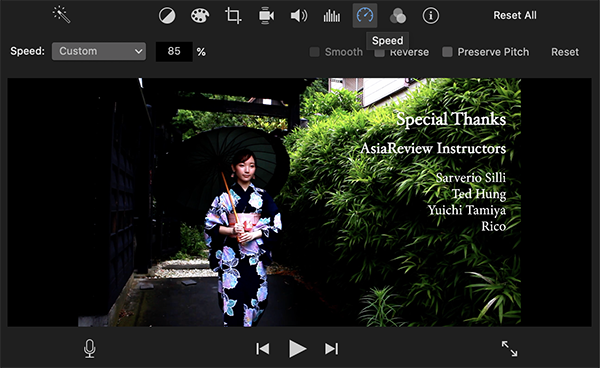
I changed the slow motion speed as the speed adjustment menu appears in the upper right corner of the screen. I changed the speed item to “Custom” and also adjusted the speed by entering any [%] in the box that appears.
Saving Video
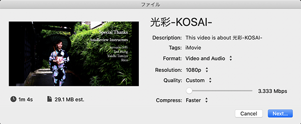
Click the arrow in the upper right corner of the screen and save the video from File.

Changed [Resolution] of video to [1080p] in advanced settings. I also changed the Quality setting to [Custom] to get the least amount of space. However, iMovie could only compress the video to a minimum of [29.1MB], so I also used other software to get it down to [10MB].
Video Compression
I used [FFmpeg] for video compression. [FFmpeg] will operate the commands in [Terminal].
Navigate to the folder you want to compress, and then enter [ffmpeg -i Compression source file Compression ratio setting Output file name].
ffmpeg -i movie_name.mp4 -crf 10 movie_name_compressed.mp4
I created [movie_name.mp4] (the original file) and [movie_name_compressed.mp4] (the compressed file’s name) with a compression ratio of 10.
As a result, I was able to compress the video down to [9.4MB].
Video Clip
This is the final presentation movie.
Creating Slides
I decided to design it to look like a fashion magazine spread and searched for reference images from [Pinterest].

And I used [Adobe Illustrator] to create the slide data.
Summary slide
This is the final slide.

3. Links to Files and Code
Programming