Molding and casting
1. Weekly Brief Summary
This week, I used the bear character created with 3D data to mold and cast.
I made silicon and wax molds from 3D data and cut them with [SRM-20].
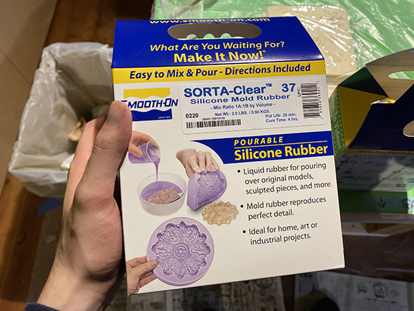
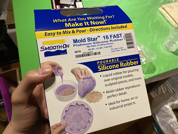
After cutting, I made a silicon mold using [SMOOTH-ON’s Mold Star].
The model was cast by casting colorless and transparent two-component epoxy craft resin.
2. Weekly Assignment Requirement
Group assignment
- Review the safety data sheets for each of your molding and casting materials
- Make and compare test casts with each of them
Individual assignment
- Design a 3D mould around the stock and tooling that you’ll be using, mill it (rough cut + (at least) three-axis finish cut), and use it to cast parts.
Learning outcomes
- Design appropriate objects within the limitations of 3 axis machining
- Demonstrate workflows used in mould design, construction and casting
Have you?
- Linked to the group assignment page
- Reviewed the safety data sheets for each of your molding and casting materials, then made and compared test casts with each of them
- Documented how you designed your 3D mould and created your rough and finish toolpaths for machining, including machine settings
- Shown how you made your mould and cast the parts
- Described problems and how you fixed them
- Included your design files and ‘hero shot’ of the mould and the final object
3. Group Assignment Link
Kamakura Group Assignment Week15
4. Description of Assignment Work
Creating Modeling Data
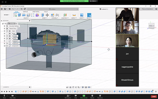
This time, I created the data using Fusion360. During the work, I referred to the documentation created by FabLab Kamakura instructor.
Mold Design in Fusion360
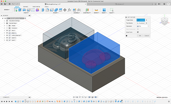
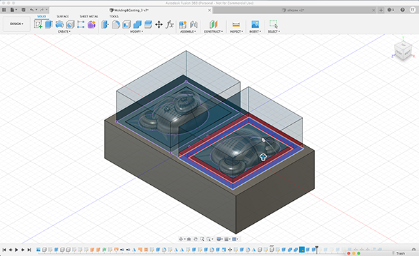
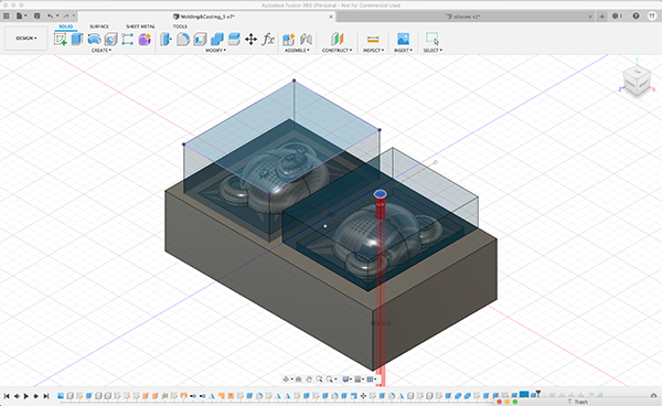
First, I placed the parts of the bear’s face in half within the size of the modeling wax I was using.
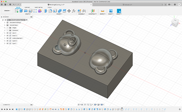
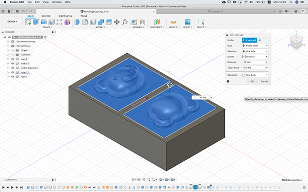
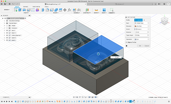
Then I sketched out a frame that was supposed to be the size of a silicon mold and extruded it to a height where it could be cut.
↓
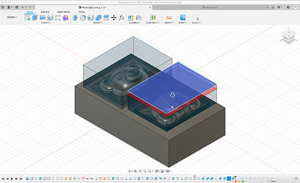
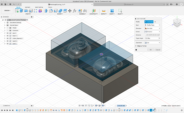
I then cut out the extruded model and the parts of the bear using [COMBINE]-[CUT].
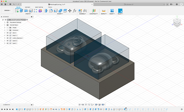
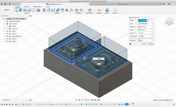
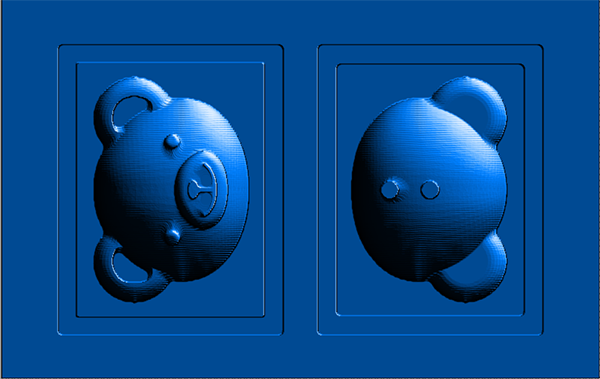
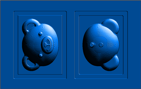
Next, I modeled the unevenness of the silicone mold to fit each part. I modeled 5mm width of the bite structure to be convex for the bear face part and concave for the back of the head part.
Face parts
↓
Rear part
↓
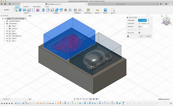
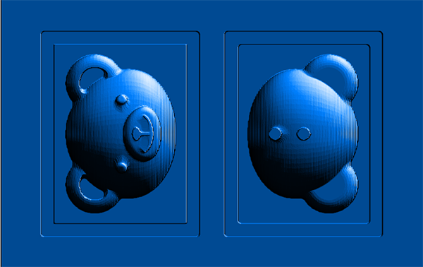
To reduce the volume of the back of the head parts, I used the [EXTRUDE] to make them smaller.
↓
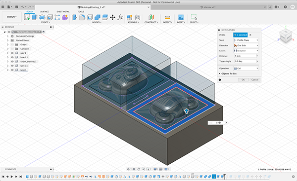
I also decided to inject the resin agent from the back of the head parts, so I sculpted the injection port and the air hole, respectively.
Inlet
↓
Air hole
↓
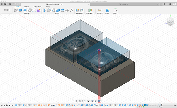
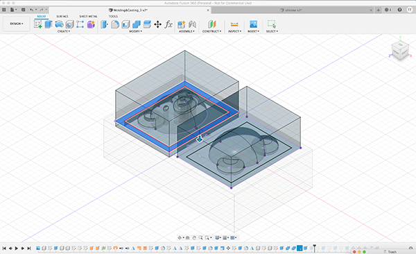
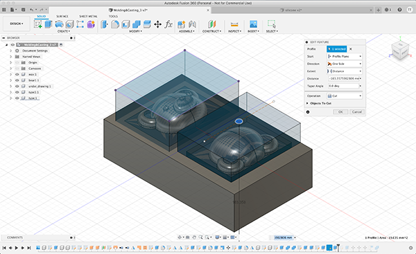
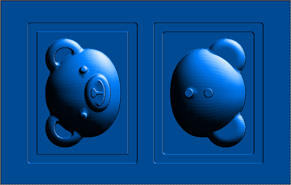
Finally, I aligned the top surface of modeling wax with the top surface of the model which will be the silicone mold, and modeled the mold by [COMBINE]-[CUT].
↓
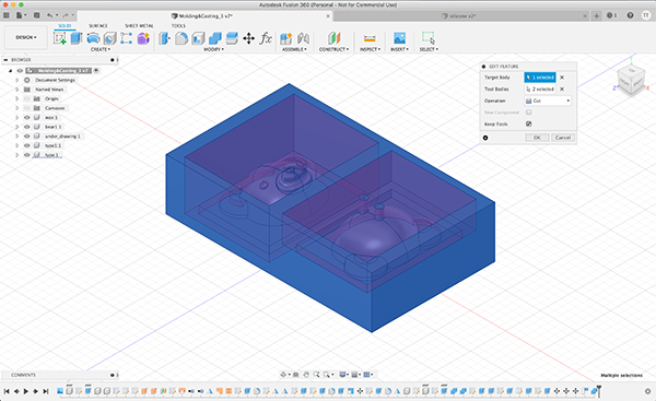
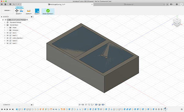
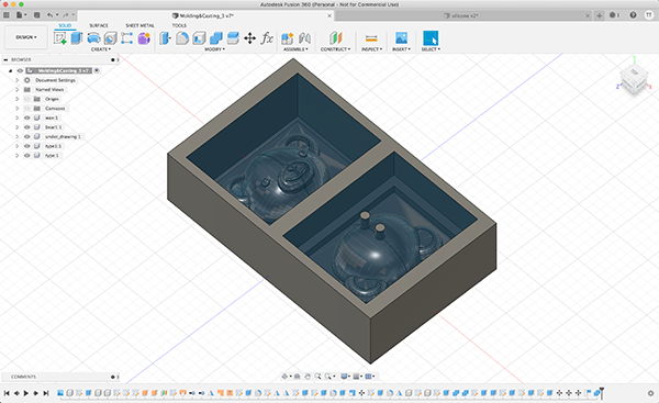
3D model of the created mold
Modeling List
Bear Character Data
Silicon Type Data
Wax Type Date
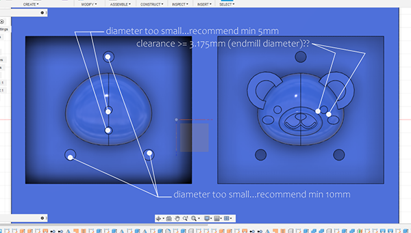
Initially, there were various problems with the data I created, such as the part that the diameter of the end mill did not pass through, and the size of the air holes and material inlets were not sufficient.
I got advice from the instructor and solved these problems.
SCutting Work with SRM-20
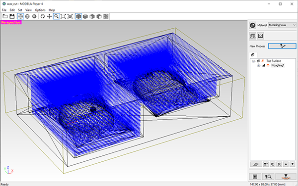
The wax cutting data created with Fusion360 was output in STL format, and CAM data was created with MODELA Player 4.
Setting of MODELA Player 4
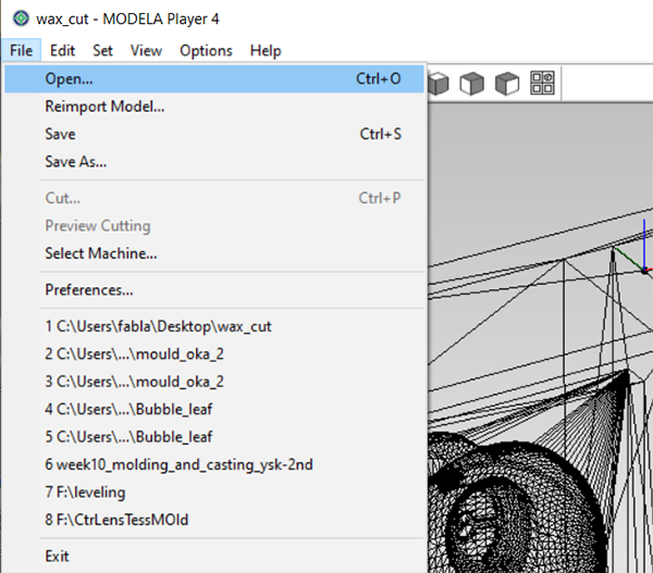
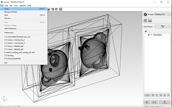
After starting MODELA Player 4, load STL data from [File] → [Open (Ctrl+O)].
↓
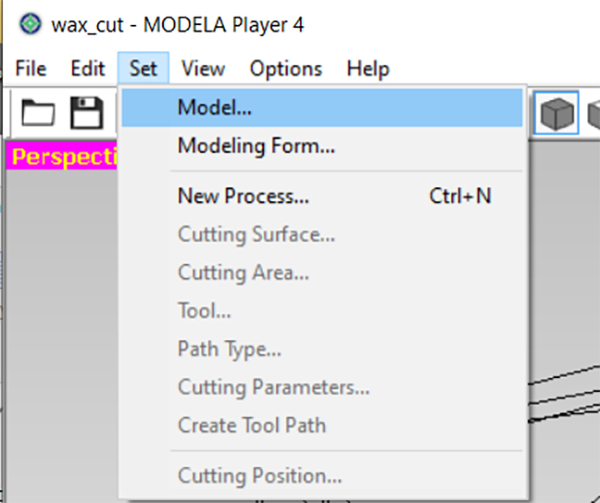
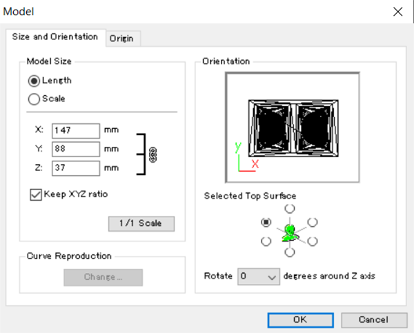
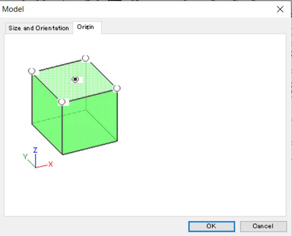
Fixed the orientation of the model when loading STL data.
The location of [Selected Top Surface] is set to the location of ○ from [Set] → [Model] → [Size and Orientation].
↓
↓
Also, [Origin] is set on the top of the model.
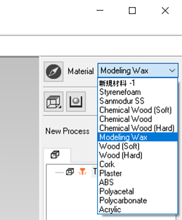
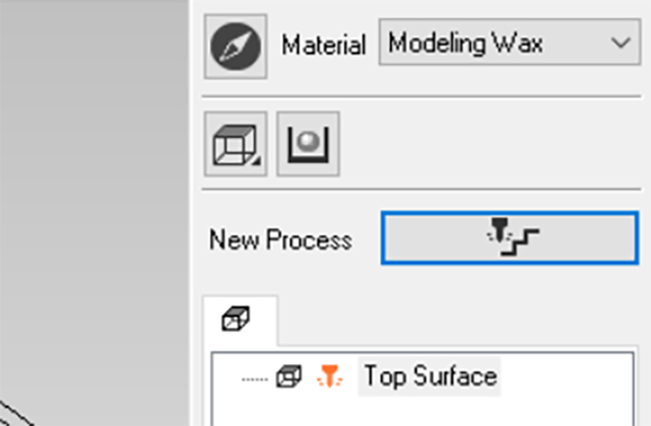
Then select [Modeling Wax] from [Material].
From here, we will create CAM data.
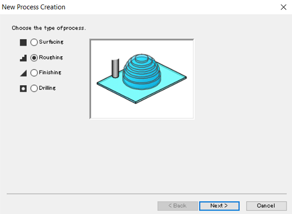
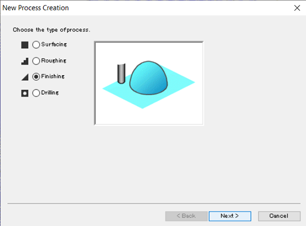
Click the drill icon to the right of New Process.
First select the machining type [Roughing].
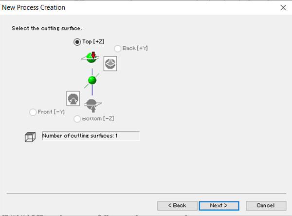
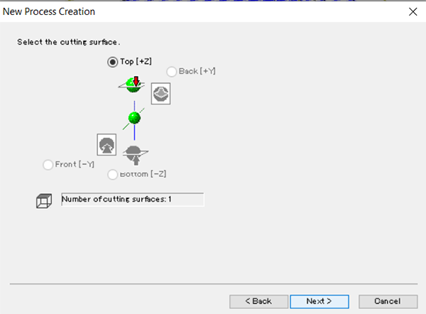
As the processing surface, the top surface with the origin set is selected.
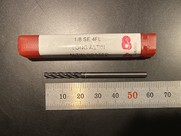
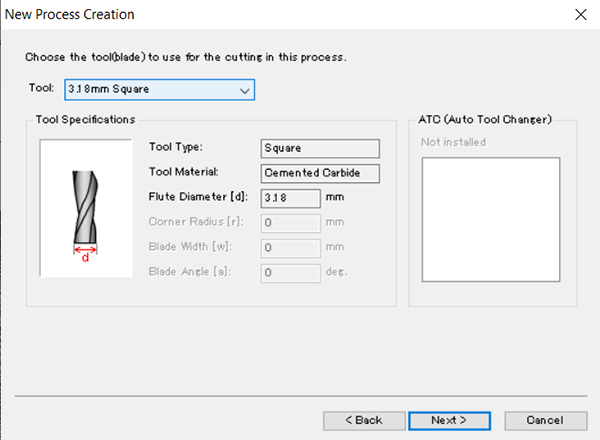
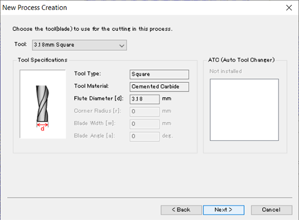
Select the end mill to use.
This time, I used [3.18mm Square] of [1/8 SE 4FL] in the lab.
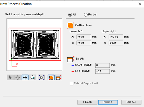
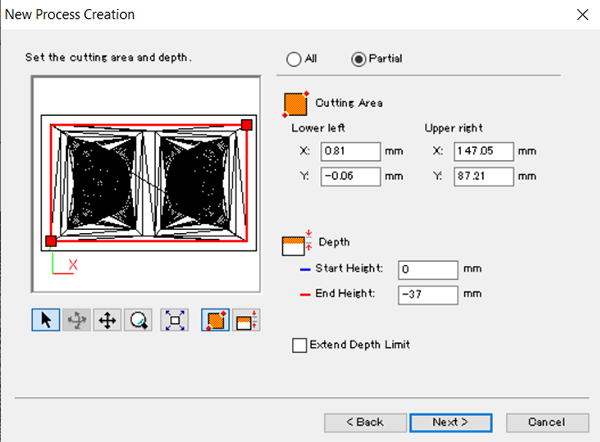
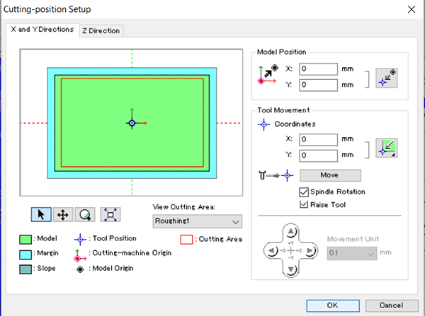
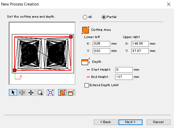
Set the processing range.
In the [Partial] mode, the machining area indicated by the red frame was manually moved to the minimum machining area.
↓
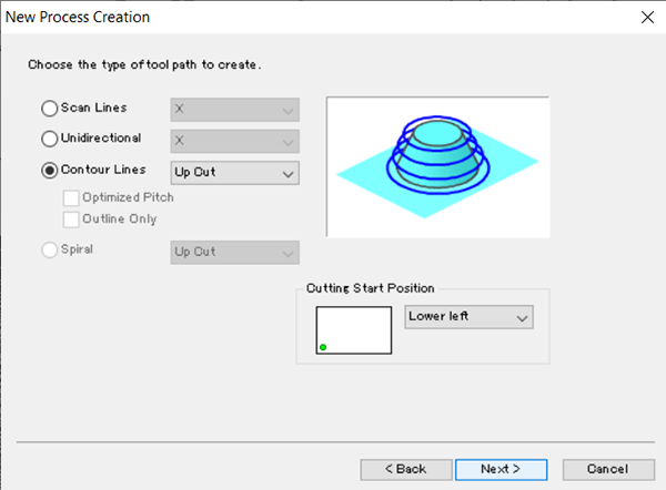
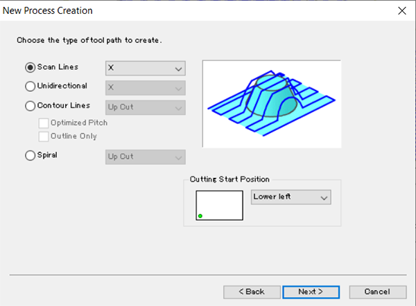
Set the tool path.
This time, I selected [Up Cut] of [Contour Lines].
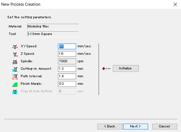
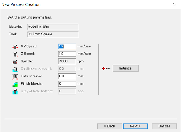
Check the detailed parameter settings for cutting.
The processing speed this time is
- XY axis・・・20mm/sec
- Z axis・・・10mm/sec
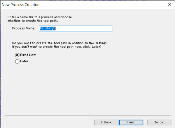
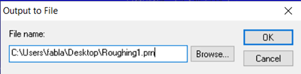
Finally set the name of the processing file.
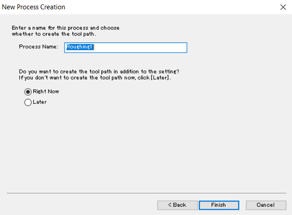
↓
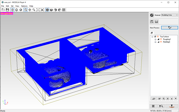
When these settings are completed, a blue tool path is displayed.

You can check the processing preview by clicking the magnifying glass icon on the bottom right of the screen.
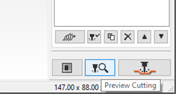
↓
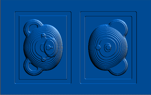
Press the [OK] button to display the cutting preview.
This [Roughing] data was found to finish cutting at [1h58m].
↓

Next, I will set the finishing process.
Select the machining type “Finishing”.
As the machining surface, the top surface with the origin set is selected as before.
Select the same drill to be used.
Set the selection manually.
Set the tool path.
This time, I selected [X] of [Scan Lines].
Check the detailed parameter settings for cutting.
The processing speed this time is
- XY axis・・・15mm/sec
- Z axis・・・10mm/sec
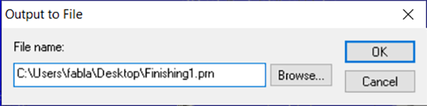
Set the name of the processing file.
↓
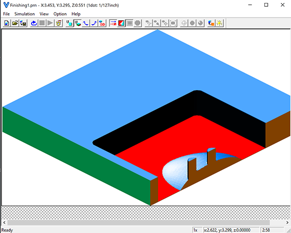
I confirmed the cutting preview after the above settings.
It’s been machined very neatly, but I wanted to reduce the cutting marks a little more and confirmed the setting of another tool path.

Check Cutting Preview
I confirmed 4 kinds of toolpath settings, and finally decided to process with [Scan Lines]-[X+Y] which is the most beautiful finish.
- [Control Lines]ー[Up Cut]

- [Scan Lines]ー[Y]

- [Scan Lines]ー[X+Y]

Now that the CAM data settings for [Roughing] and [Finishing] are complete, output a PRN file to read with [VPanel for SRM-20].
Click the drill icon.

↓
Material Processing
Setting Material
This time, use [Milling Wax] of [ferris].
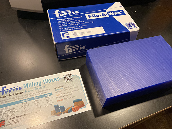
Secure the modeling wax to the table with double-sided tape.
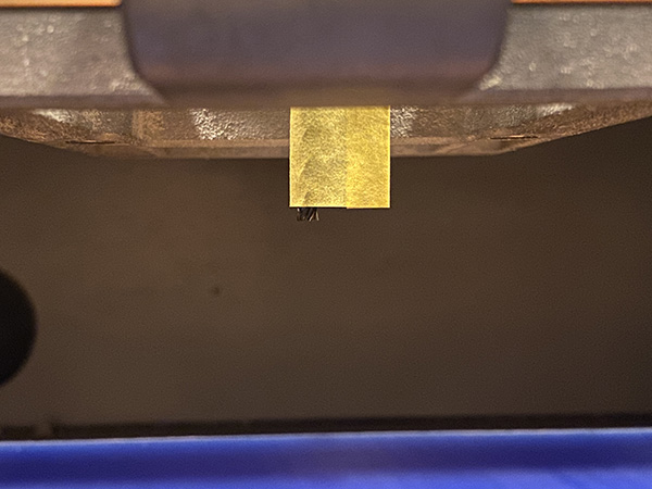
After checking the data, the maximum depth was [30 mm], so it is necessary to remove the end mill from the chuck by 30 mm or more and fix it.
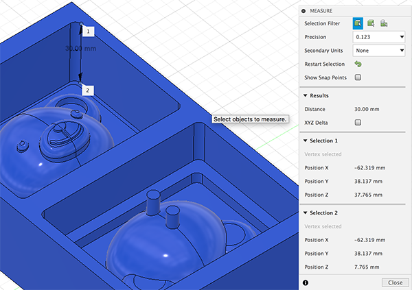
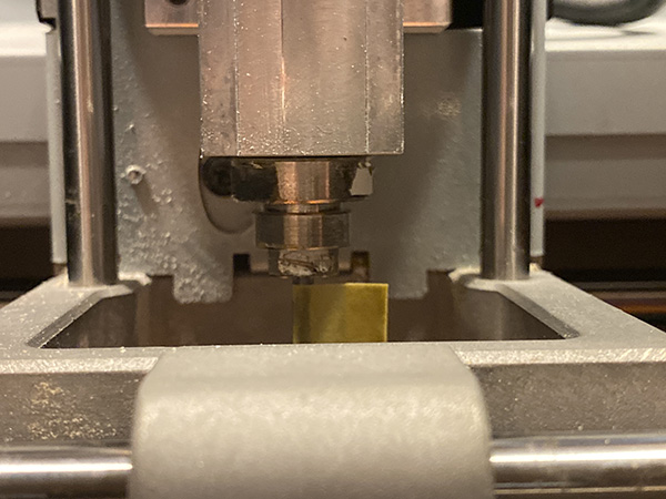
Therefore, I decided to cut out the masking tape to [35mm] size, attach it to the end mill, and attach it so that it would stick out enough length from the chuck.
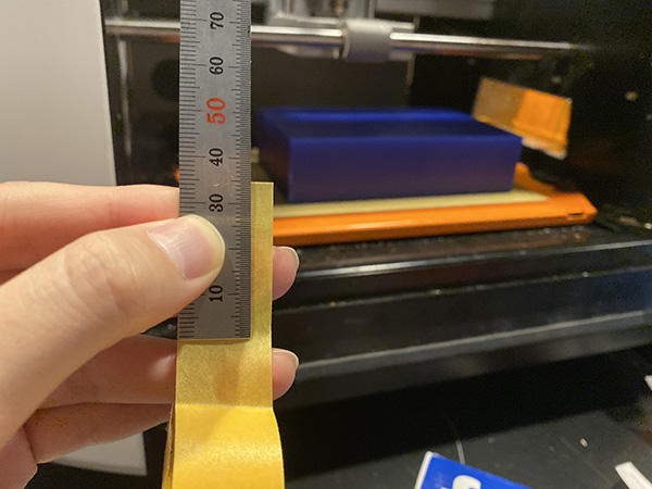
↓
It was confirmed that the masking tape protruded a few mm from the cut-out masking tape.
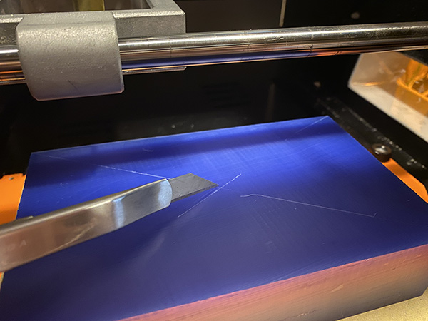
Write the origin location on the wax using a cutter knife.
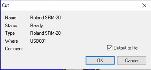
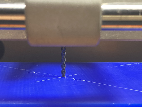
Start [VPanel for SRM-20] and align the center of the end mill with the origin position written earlier.
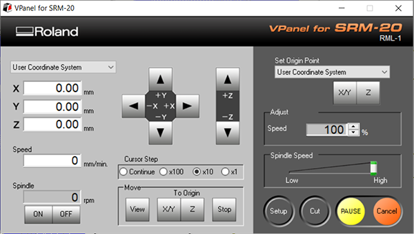
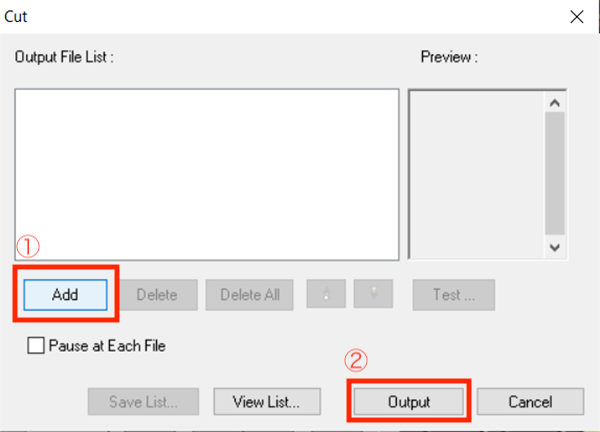
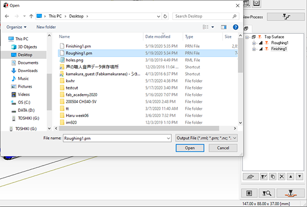
Click [Cut] of [VPanel for SRM-20] and load the PRN file created earlier.
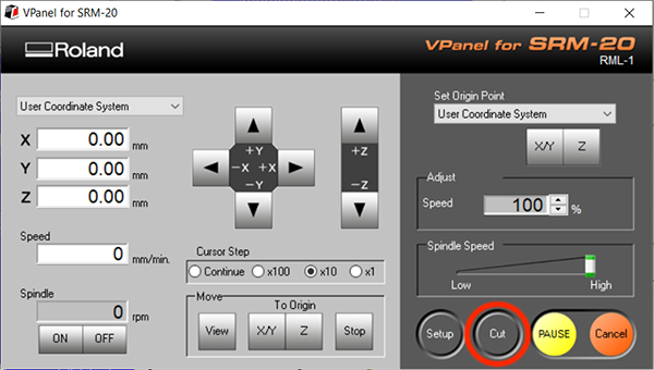
Click Add and select Roughing1.prn. After reading the data, press [Output] to start cutting.
↓
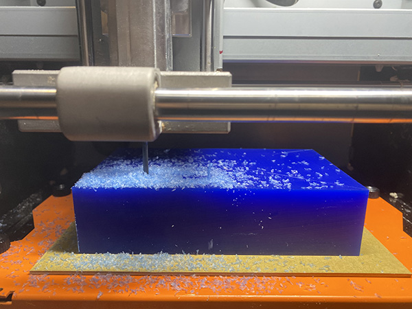
After a few hours, the cutting noise stopped, so I removed the scraps and checked the model.
Then, the [Roughing] data was not processed to the end.
When checking the screen of [VPanel for SRM-20], error information was displayed.
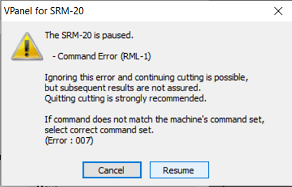
When I confirmed it with the application of the instructor, apparently it was because the machining range of the Z axis of the CAM data was generated only to a portion shallower than the created data.
However, in the preview screen of [MODELA Player4], even the most cut part was displayed, so I clicked the [Resume] button multiple times and forcibly moved it.
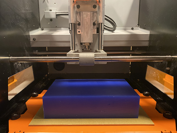
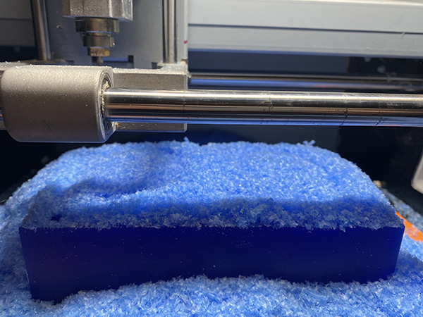
[[Roughing] data has been successfully cut.
After that, the [Finishing] data was processed by the same procedure.
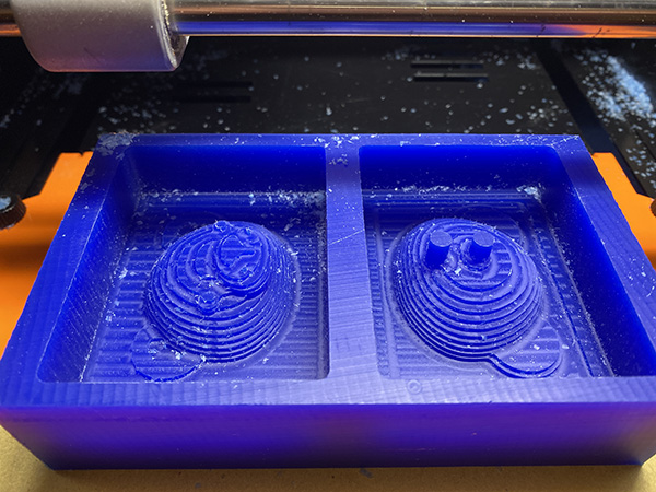
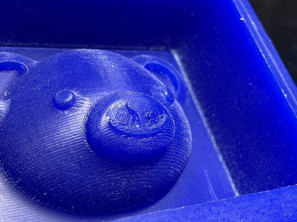
- Front
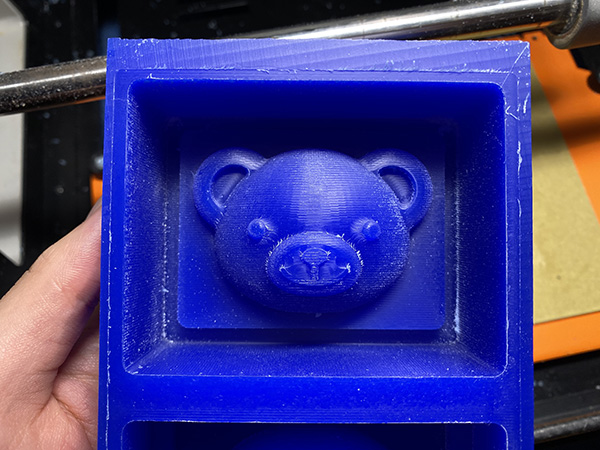
- Back
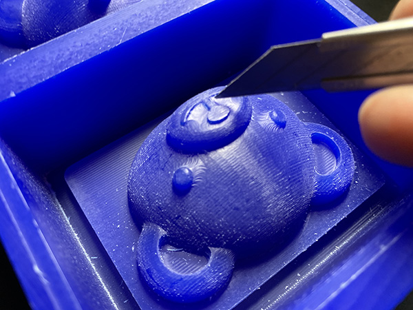
I didn’t confirm it enough in the preview, so I thought that the cutting of the mouth part was shallow and I could not cast it beautifully when I made it into a mold.
So I used a cutter knife to manually cut the mouth.
↓
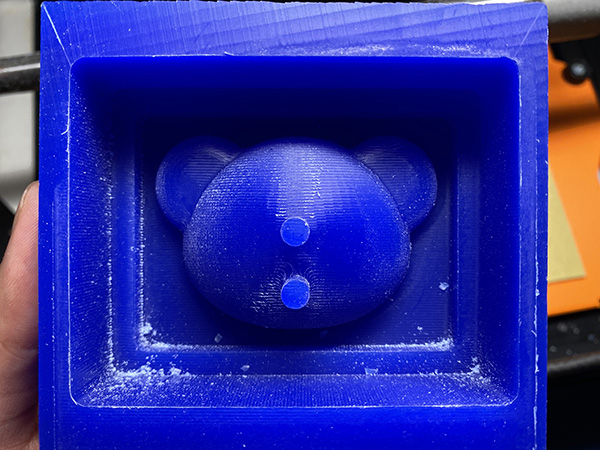
Making Silicone type
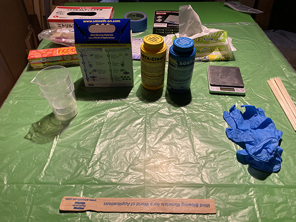
Safety Measure
When making a silicon mold, it is necessary to maintain a working environment due to the characteristics of the material.
- Provide adequate ventilation in the room
- Prepare rubber gloves to prevent direct contact with the material
- Wrap the scale
- Lay vinyl sheets on the table and floor
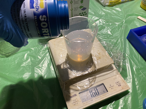
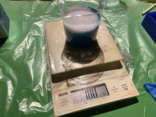
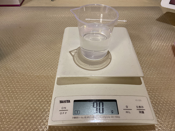
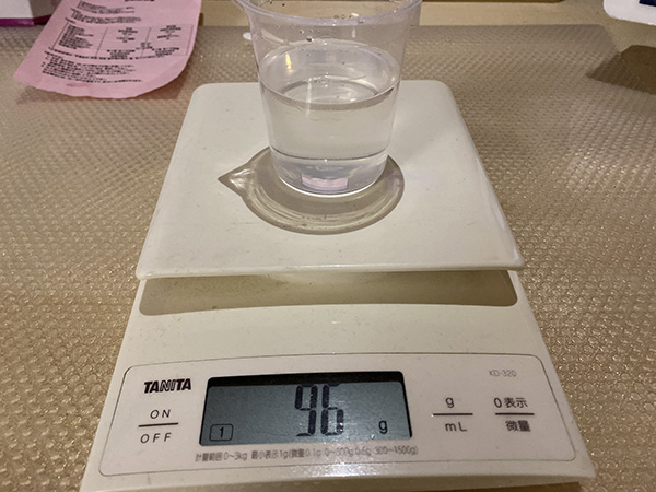
In order to make a silicone agent, it is necessary to mix two types of liquids A and B in the same mass. I proceeded with reference to Documentation of the instructor Kae-san.
- Material A・・・80g
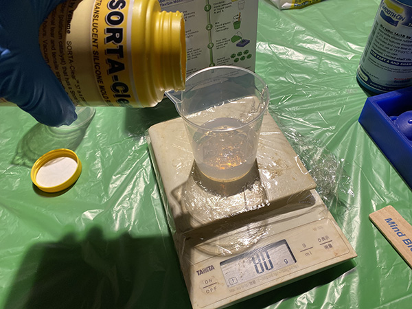
- Material B・・・80g total=160g
↓
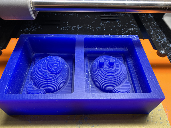
The mixed materials were poured into a cut wax mold.
But I realized that I was making a big mistake.
The material poured into the wax was not for making the silicon mold, it was the material for finishing.
Originally, it should have been a light blue mixture, but it remained colorless and transparent, so I found something strange.
So I quickly put the mixture back into the measuring cup, but it was too viscous to completely remove it.
So I decided to wait until the liquid was completely cured.
Causes of Using the Wrong Silicone Agent
I’m fully aware of my lack of confirmation, but I made a mistake because the packaging of the silicone agent for the mold and the silicone agent for the finish were very similar.
- Silicone agent used for finishing
- Silicone agent used for silicon mold (← correct answer)
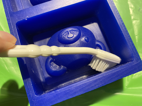
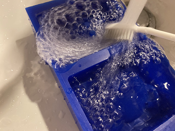
After a few hours, the finish had hardened and I used a toothbrush to remove the rest of the wax.
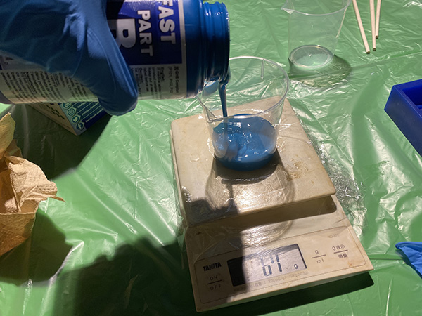
[Mold Star] mixes A and B liquids of the same mass.
- Material A・・・80g
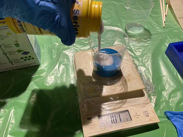
- Material B・・・80g total=160g
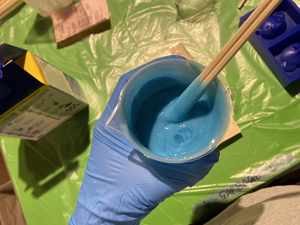
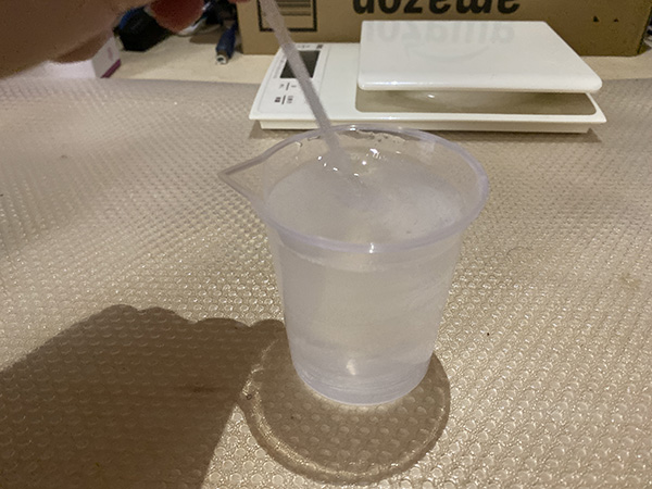
The mixed liquid should be stirred within 6 minutes.
The speed of turning the rod has been increased or devised so that there is no unevenness.
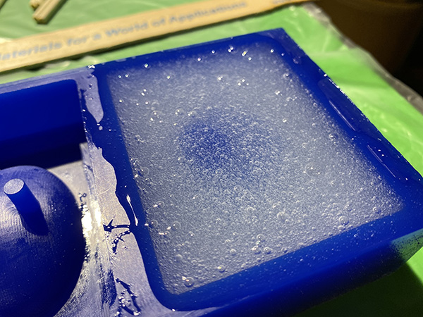
The mixture was poured little by little into a wax mold.
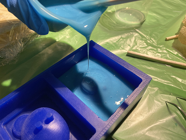
I assumed that the amount of the mixed liquid would decrease when the air escaped, so I poured it until it slightly overflowed from the inside of the frame.
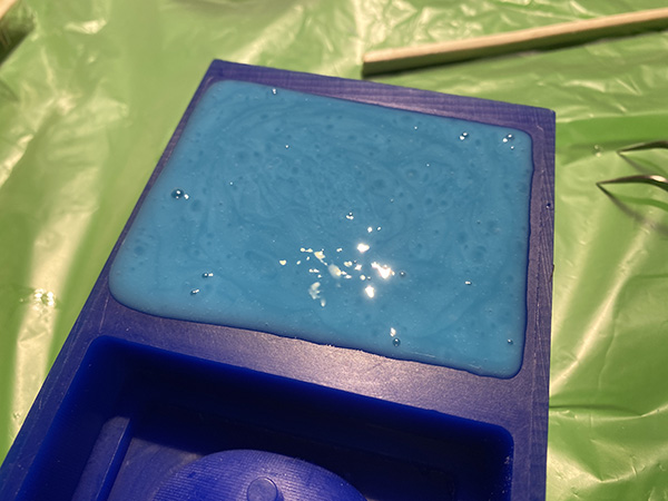
Device for Defoaming
Since there was no equipment such as a vacuum defoamer in the lab, I decided to use a cordless belt sander to vibrate the wax mold for defoaming.
I pressed the belt sander against the side and bottom of the wax for about 15 to 30 minutes.
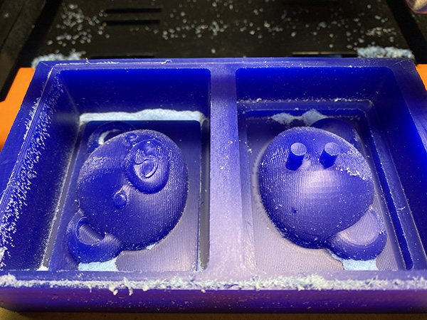
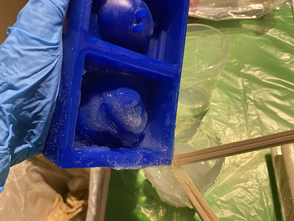
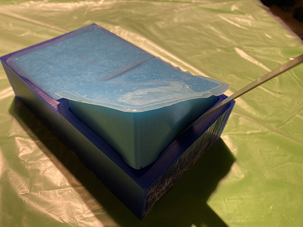
After 1 hour, it was confirmed that the silicone agent had sufficiently hardened, and it was removed from the wax mold.
In order to prevent the silicon agent from being damaged when taking it out, we devised a ruler that was inserted from the edge of the frame and pushed out using the lever principle.
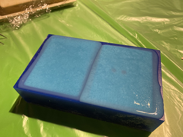
Neither type was able to produce enough air marks to affect the casting model. I was able to successfully defoam.
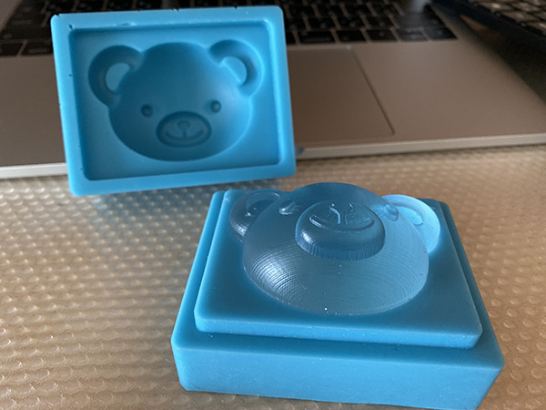
- Front part mold
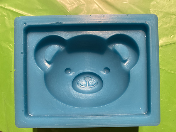
- Back part mold
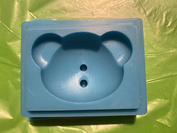
↓
When I combined the two molds, I confirmed that they fit together without any gaps.
Casting
The casting material I used this time takes 24 to 48 hours to cure, so I decided to work at home considering the possibility of heat generation.
I cleaned the inside of the silicon mold in advance and prepared it so that dirt such as dust did not adhere.
Also, the joints were covered with masking tape to prevent the material from leaking.
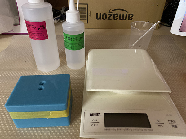
Creating Castings
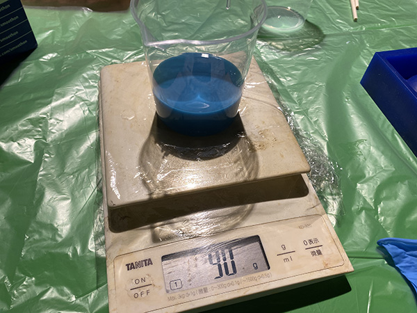
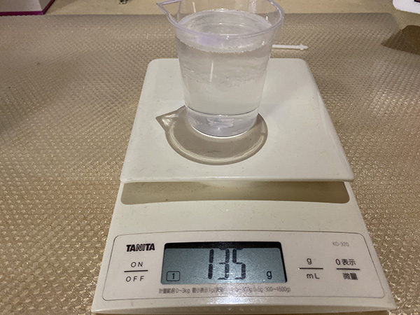
There are two kinds of ingredients, this agent and the curing agent, and they are mixed at a ratio of 100:50.
- Main Material・・・90g
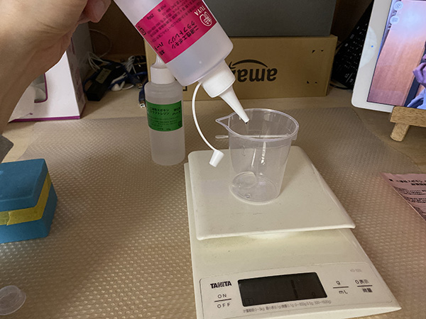
- Cure Material・・・45g total=135g
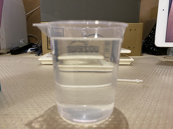
This is a material that does not cause any problems if stirred within 100 minutes, so I mixed it without thinking about air so that uneven stirring would not occur anyway.
After that, I left it for tens of minutes and waited for the air to escape.
The air was completely evacuated just by leaving it.
Gently pour the material through the inlet. I put it to the extent that it slightly protrudes from the hole.
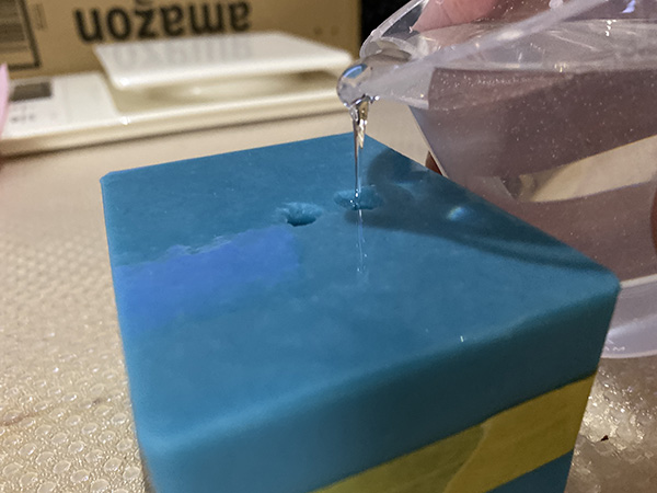
The amount used was about 40g.
To be honest, I didn’t know how much I needed, so I made too much.
After leaving it for a while, I confirmed that air was coming out of the hole.
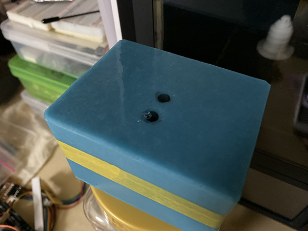
↓
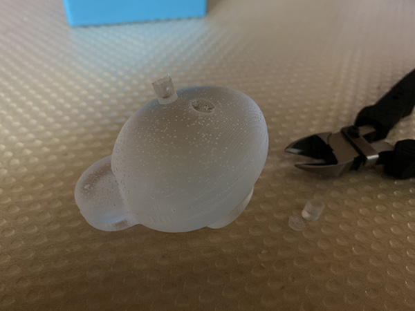
After 16 hours, I couldn’t stand until 24 hours and opened the mold.
Although it was not the time for the material to completely cure, a model was completed that was hard enough to leave no fingerprints or other marks when touched by hand.
The protruding material is attached to the side of the model.
Also, although there is not much air left in the front part, I confirmed that there is a lot of small air in the back and ears.
I thought this was due to the fact that there was no equipment for defoaming and that the model had a structure in which it was difficult for air to escape.
The air hole and inlet part were cut off using a nipper.
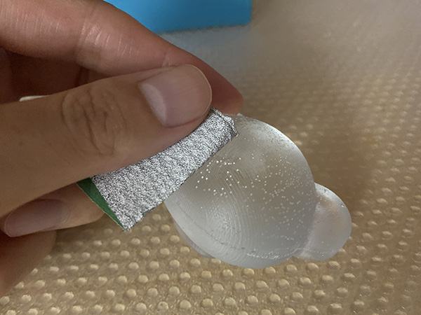
In addition, the burr created when excised was ground with a file to prepare the surface.
The file used this time is 120.
Then the surface became white and the transparency was lost.
I need to fix it with a finer finishing file.
↓
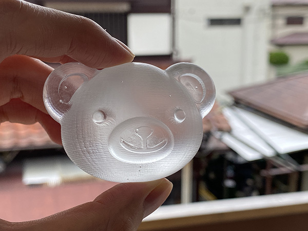
Completed Model
5. Description of Important Weekly Learning Outcome
I understood that if I didn’t pay attention to the proper location and size of the air holes, it would affect the quality of the casting.
It is also important to remove bubbles when making a mold or mold.
But this was a very difficult task.
This time I used belt sanders instead of vacuum defoaming machine, but it took a lot of work.
I used a material that has a long curing time and is easy to remove air.
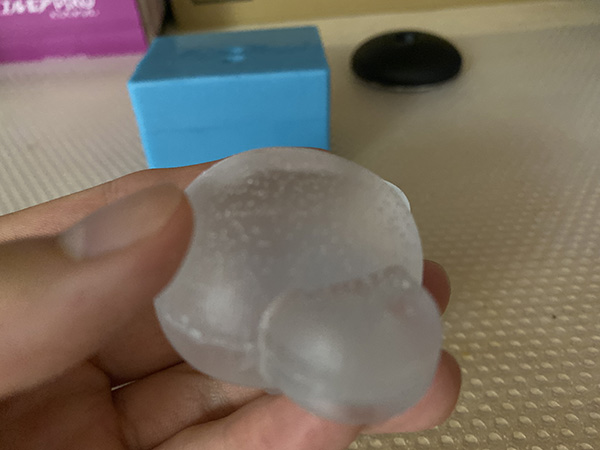
However, there were many small bubbles left on the back of the model.
Also, although it is a colorless and transparent material, the cutting marks on the surface of the model impair transparency.
If I do sanding, I think the transparency of the casting will be increased.
6. Links to Files and Code
7. Appendix
None