3D Printing & Scanning
3D printing or additive manufacturing is a process of making three dimensional solid objects from a digital file. The creation of a 3D printed object is achieved using additive processes. In an additive process an object is created by laying down successive layers of material until the object is created. Each of these layers can be seen as a thinly sliced horizontal cross-section of the eventual object. 3D printing is the opposite of subtractive manufacturing which is cutting out / hollowing out a piece of metal or plastic with for instance a milling machine. 3D printing enables you to produce complex shapes using less material than traditional manufacturing methods.
This week, we learned the basics of 3D printing, where I designed a 3D shape and printed it on one of the available tools called "Ultimaker 2 +", so that you can print any shape or three-dimensional shape in 3D with a short period of time.
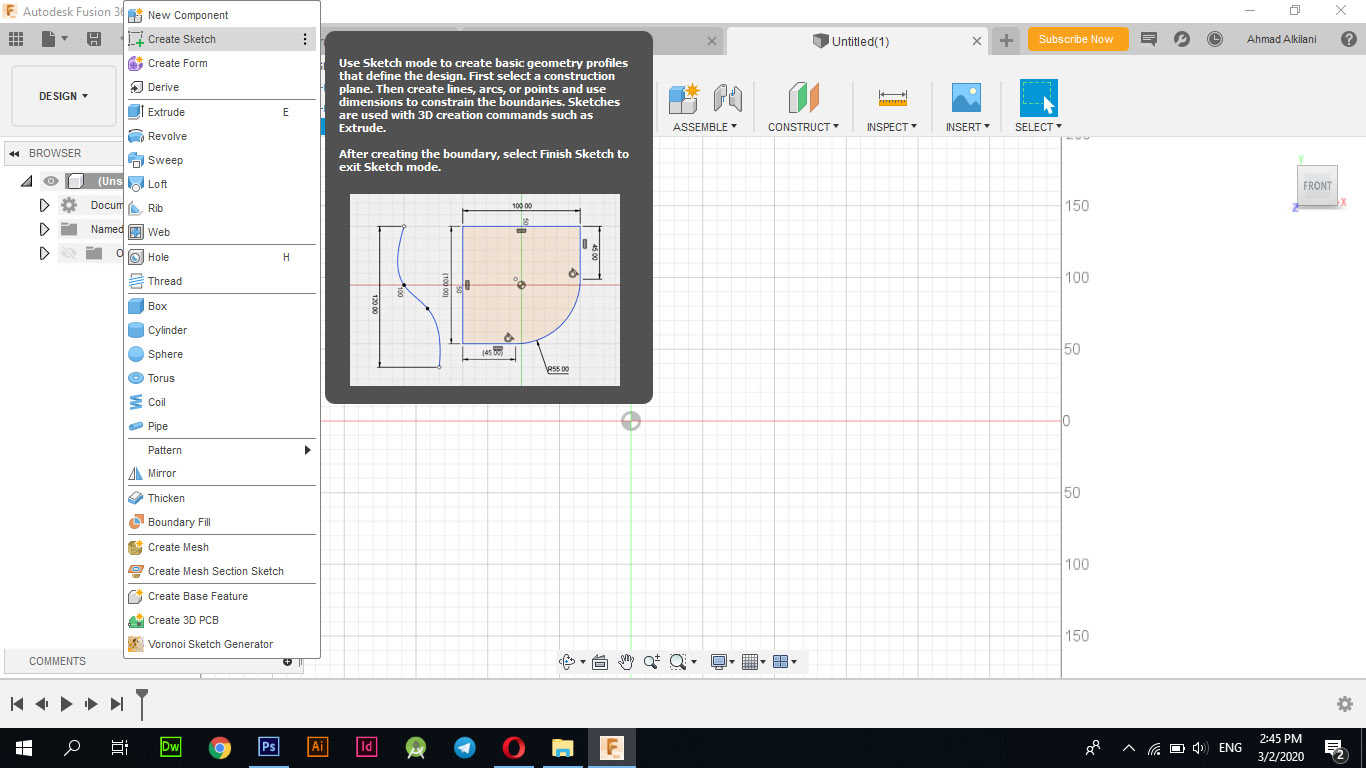
I did the design on Fusion 360, which is a 2D and 3D design program. I opened a new file and started the design - continued:
Through "Create Sketch" I have identified the entity I want to draw upon during the design and some basics to go to the entire building design.
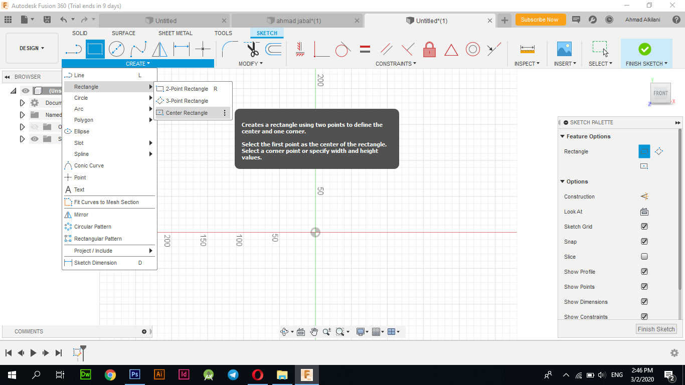
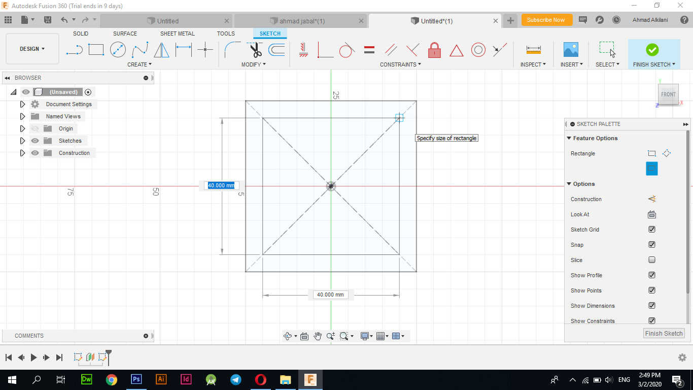
Through "Create - Rectangle - Center Rectangle" I got a square with the dimensions I want and at the same time this option allows the square to be drawn from all directions with equal dimensions unlike the number one option which depends on a side anchor.
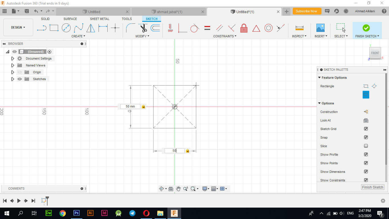
After moving to the design stage of the layers and converting them to the desired shape, in the first step I made a square with dimensions of "5 * 5 - cm".
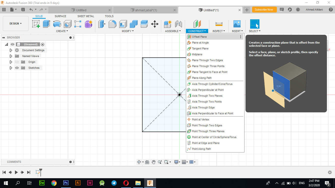
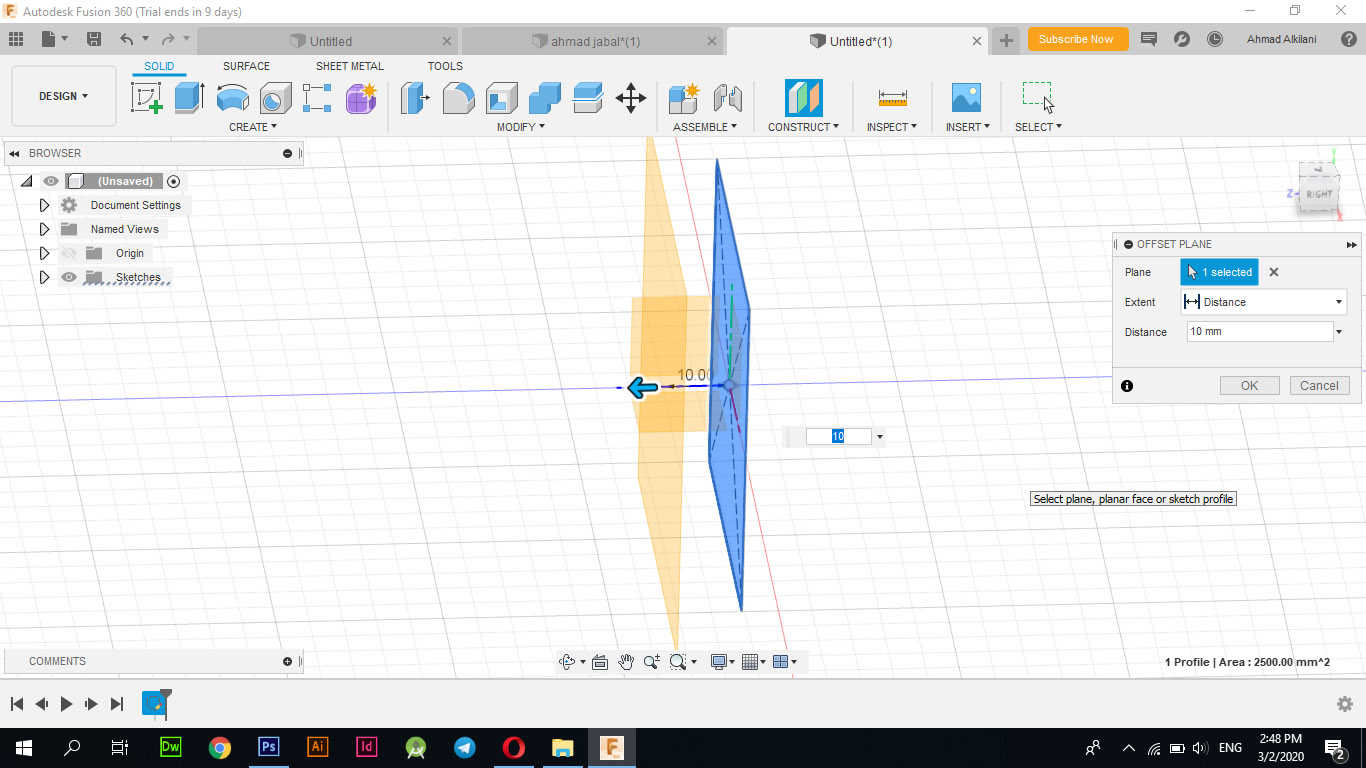
After I drew the square, I drew another square over it and to be able to do that I used the option "Offset Plane" and I set the distance between the two boxes that I want as I chose a ratio of "10 mm".
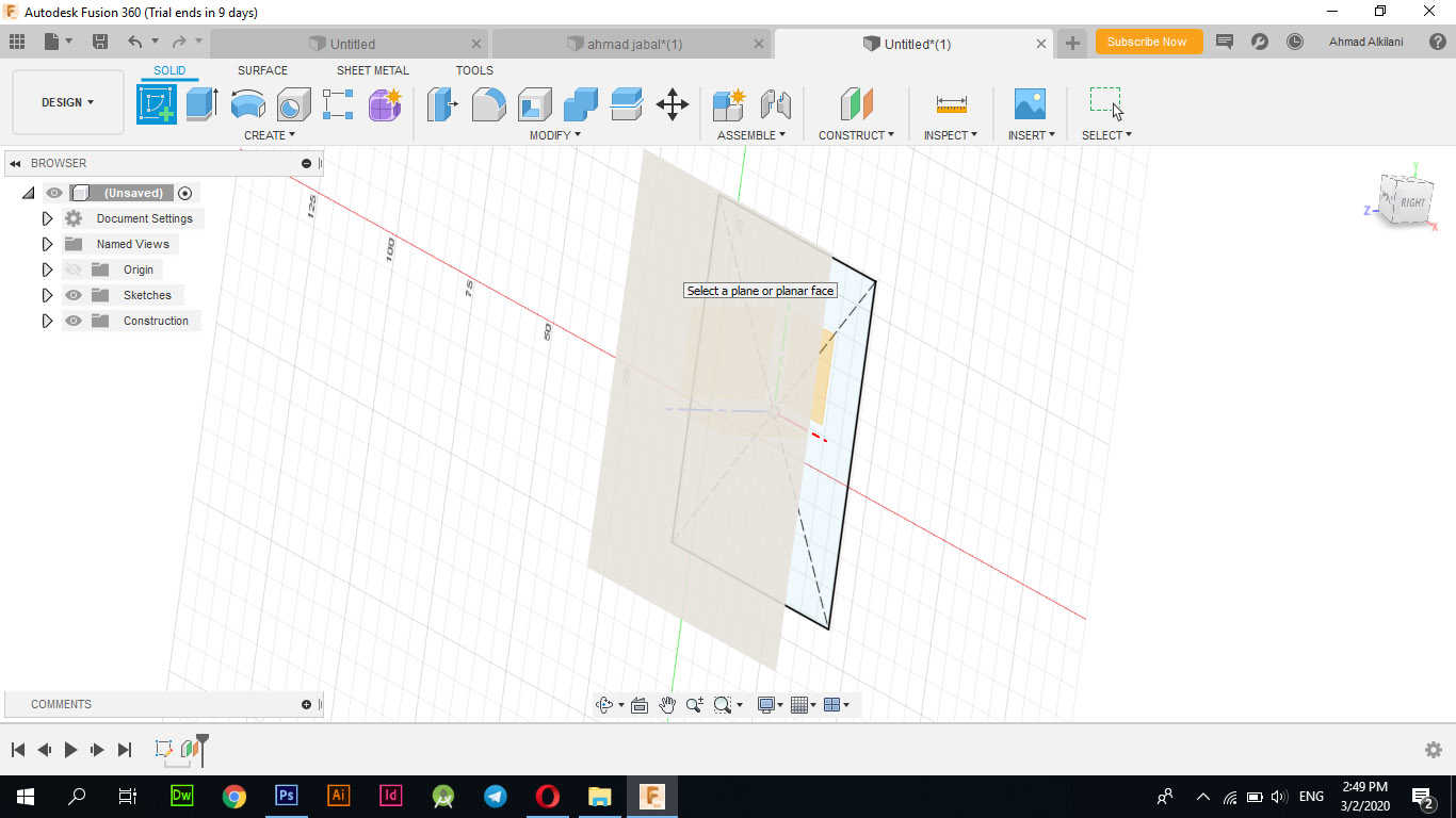
A new place has been set "10mm" from the default anchor point, and now I can draw on it with "Create Sketch".
This layer marked with a pale color above the square is the new layer on which I will draw the square above it
Of the same option the first time I choose a new square and draw it "10 mm" less than the base to cause the design to bend.
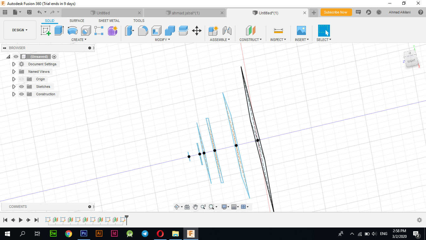
I wanted to move the square at an angle of "---" to create a retreat to give the design a more aesthetic, I did through the "MODIFY - Move / Copy" tab or I can press the "M" button on the keyboard and I can open the option.
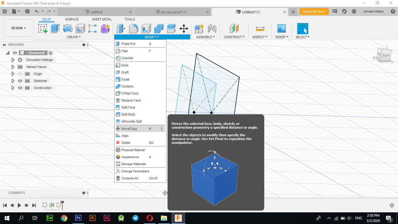
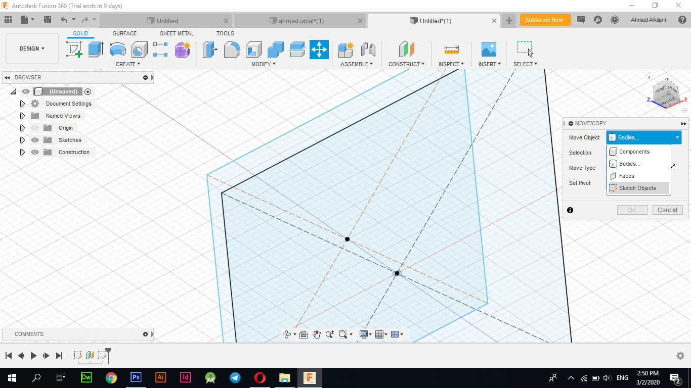
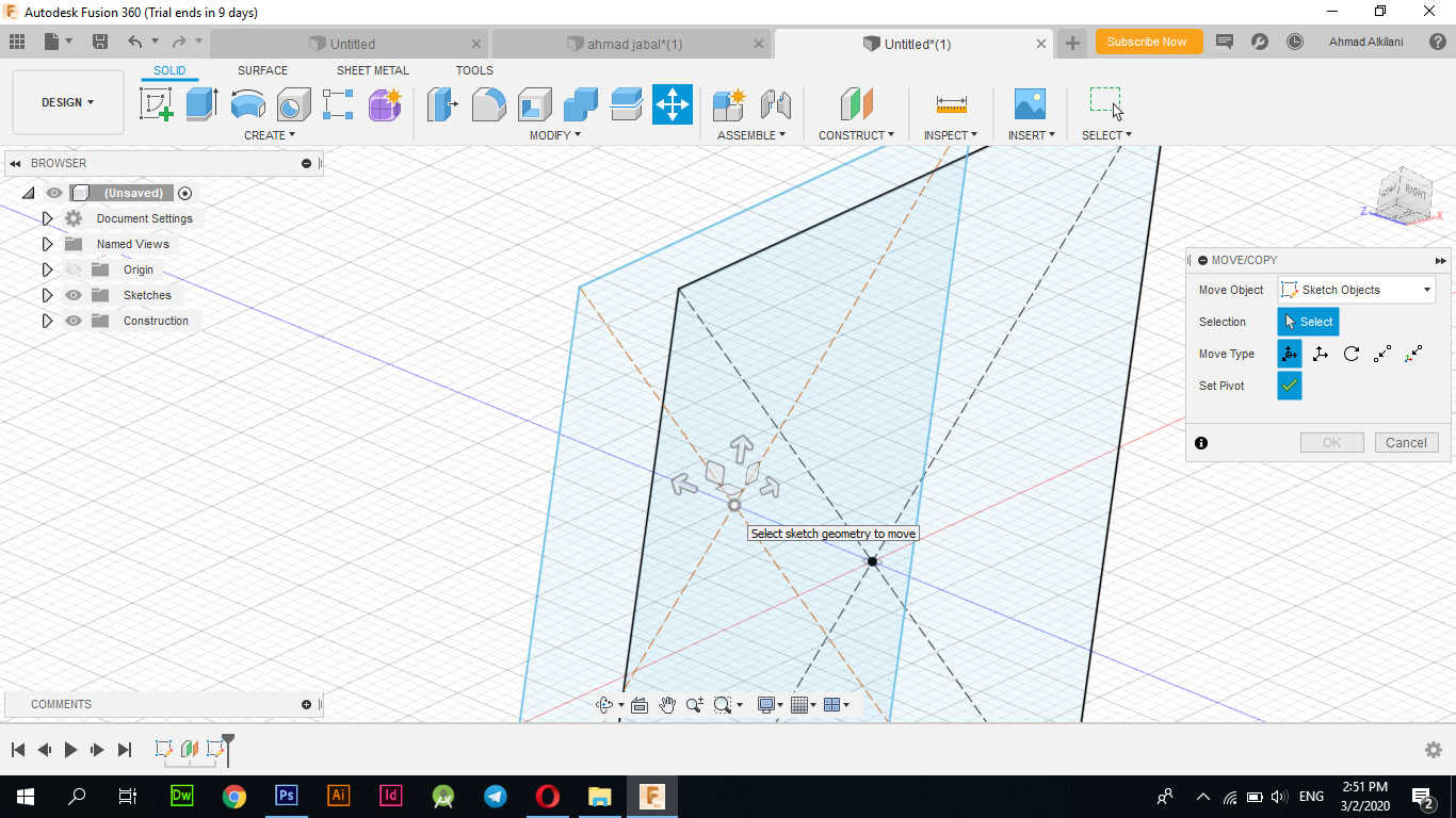
Since the design is still in its infancy and is just a drawing I have set the graphic as “Sketch” in the top option of “Move / Copy” to be able to select the part I want to rotate at an angle of "---" I have already selected it and start to rotate it.
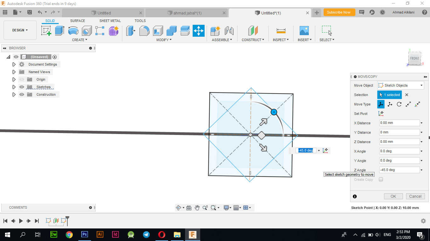
I shifted and rotated it by "45" degrees, with the indicator "Z Angle".
Gradually and by repeating the steps and in each new layer I rotate it by a certain angle so that the tilt features appear on the shape at the end also in each new layer I change its size from the previous layer, through the option "Offset Plane" I was able to control the height of each plate from us by selecting The distance between them.
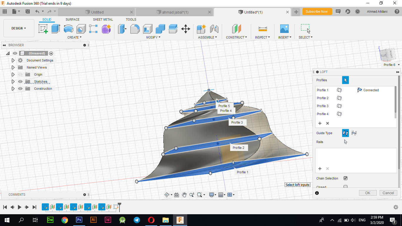
To convert the shape to a 3D object and to fill in the gaps between the layers, I used the "Loft" option, which allowed me to convert the shape to 3D - "CREATE - Loft".
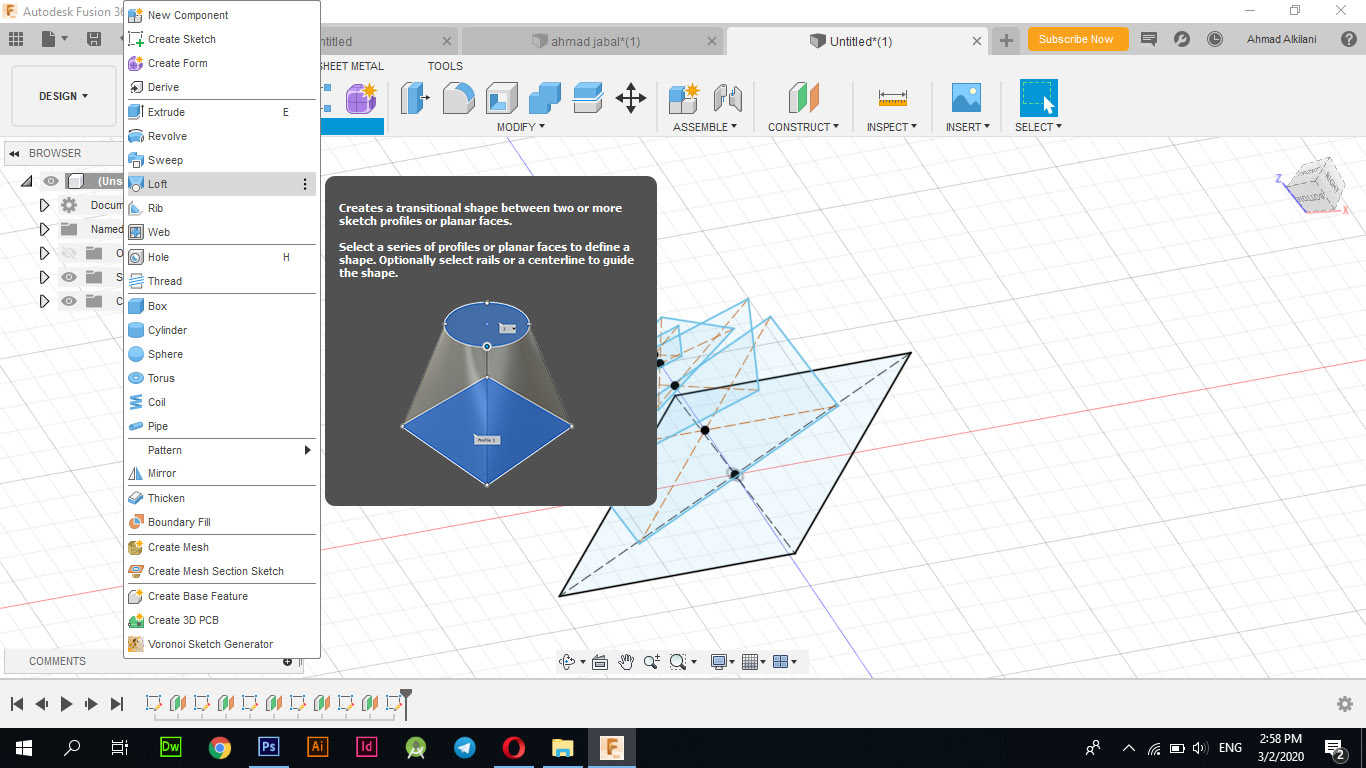
I chose the layers that I want to fill in the blank between them and agreed to the command and I have this shape.
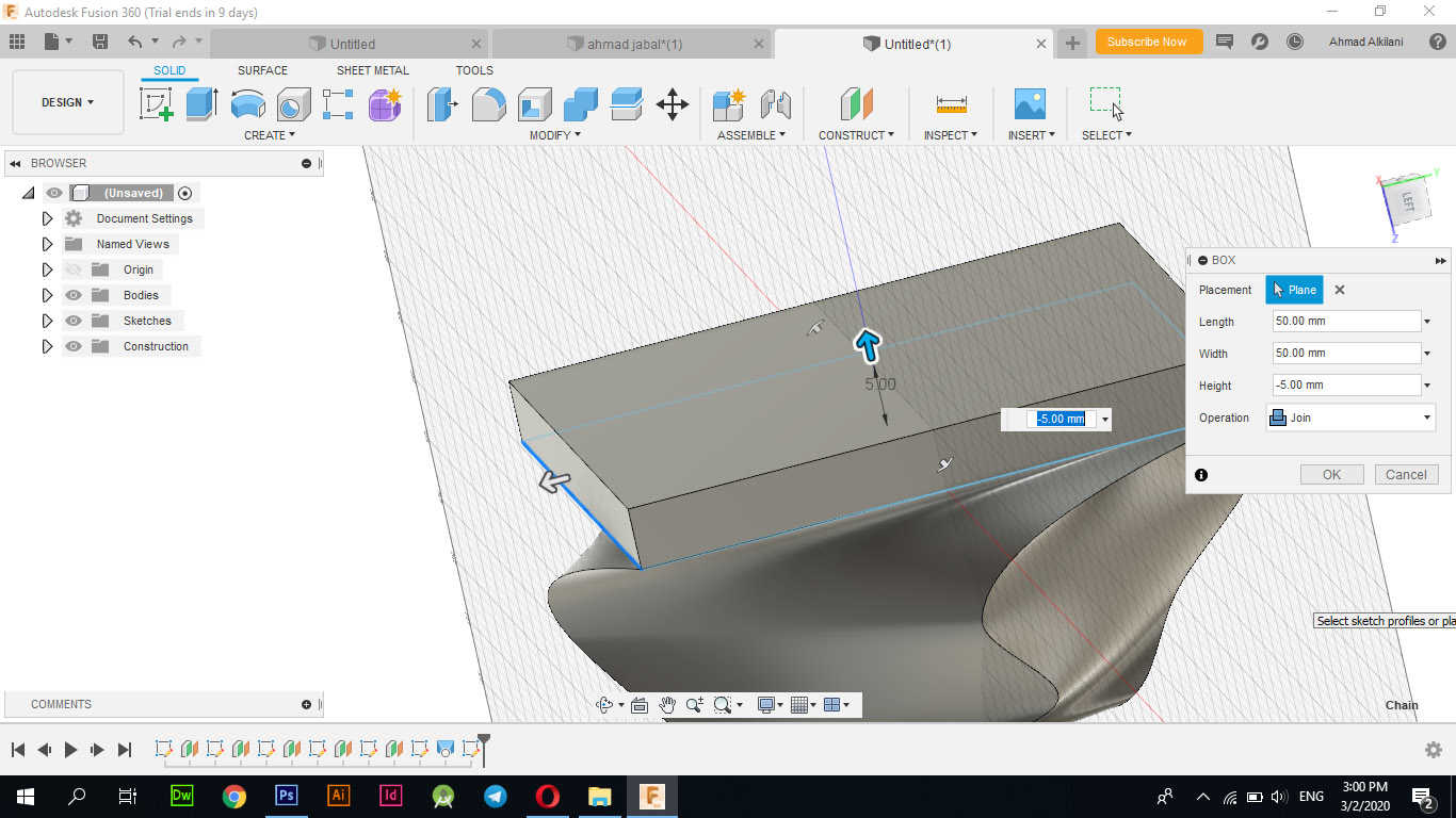
I created a square at the bottom of the pyramid to be an anchor point on the ground with a height of "50 mm".
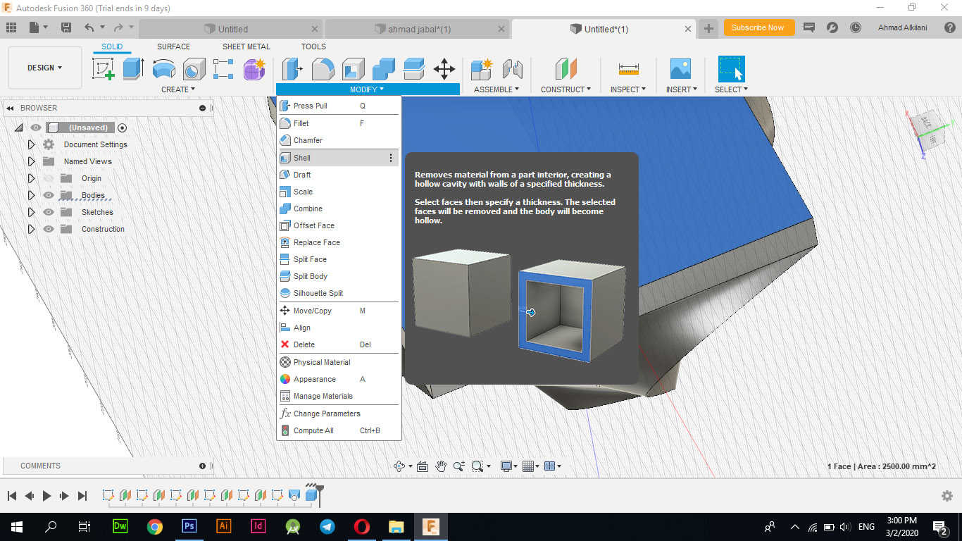
With "Shell" unload the interior of the design to ensure the machine takes less time on the job.
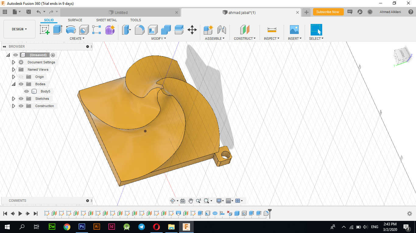
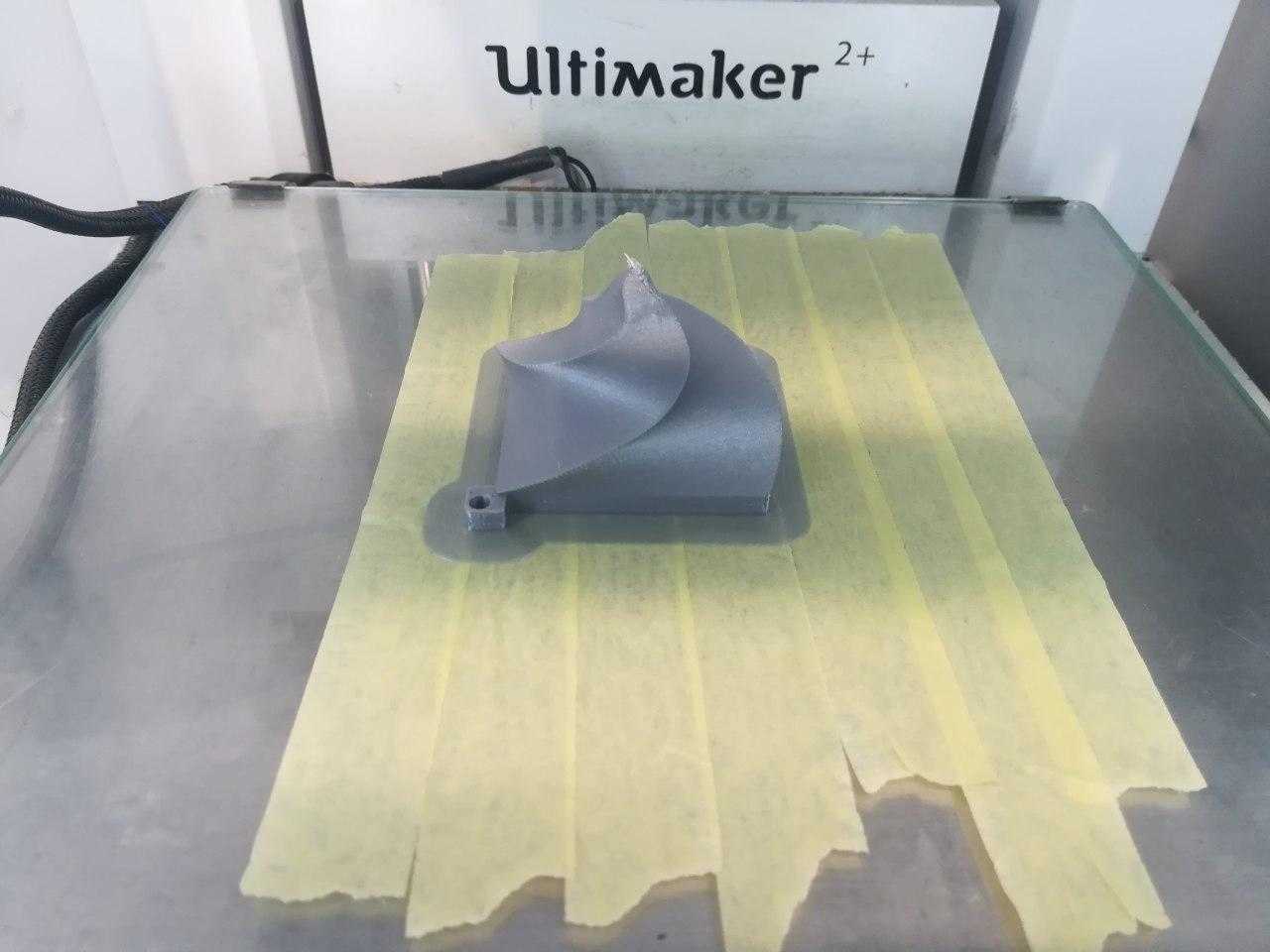
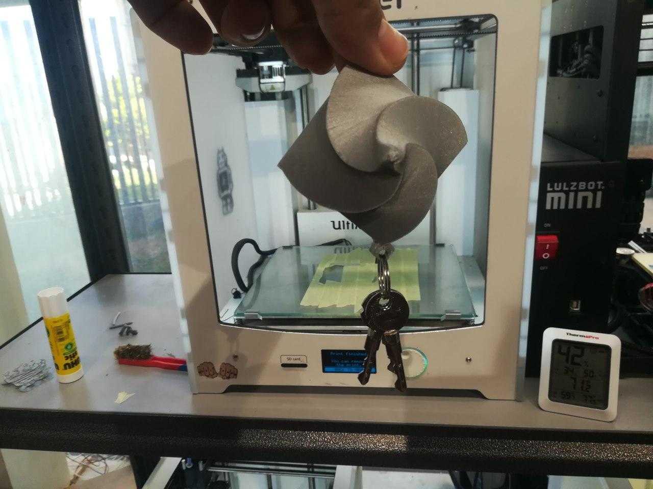
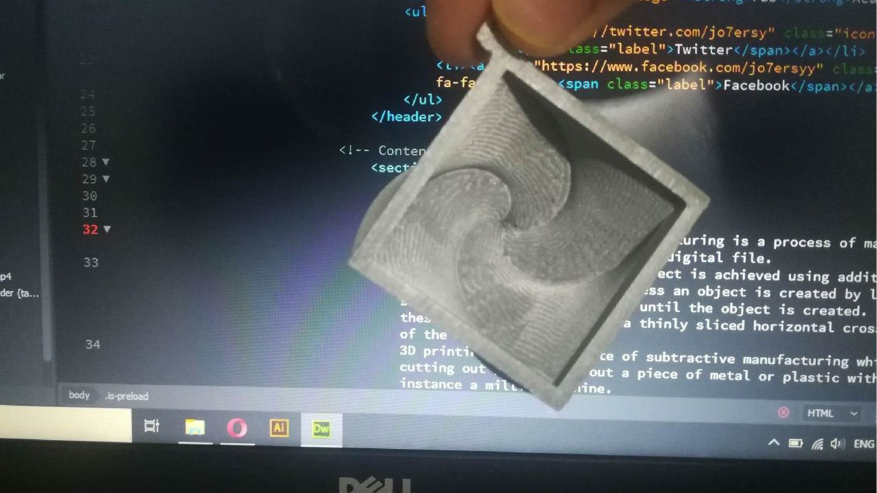
This is the final design, this design can be used to hang the key with it or just a view that adds aesthetic to its stature.
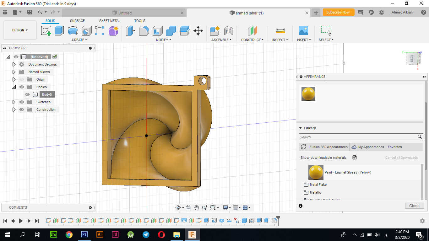
I saved the design as "STL" by right-clicking on "Body" in the side menu of layers, then saving as "STL".
Cura
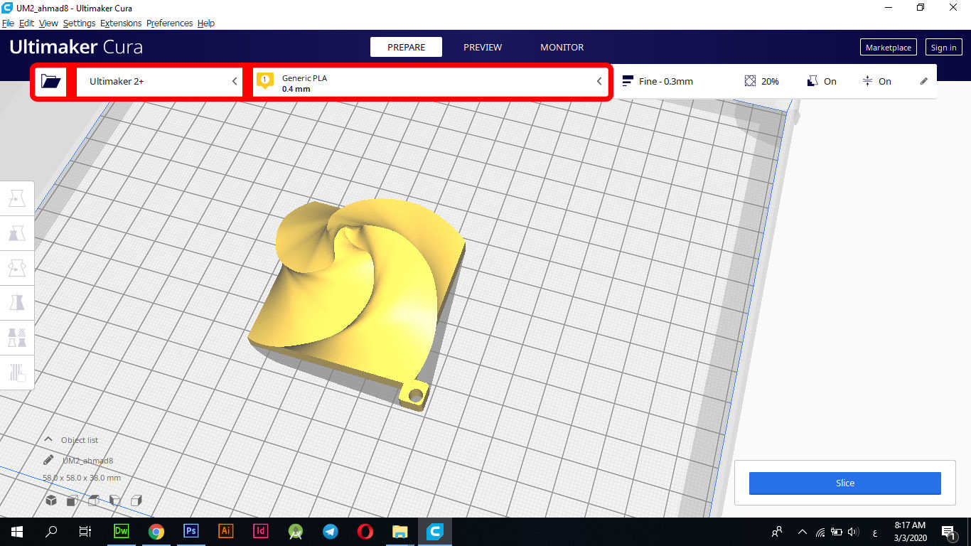
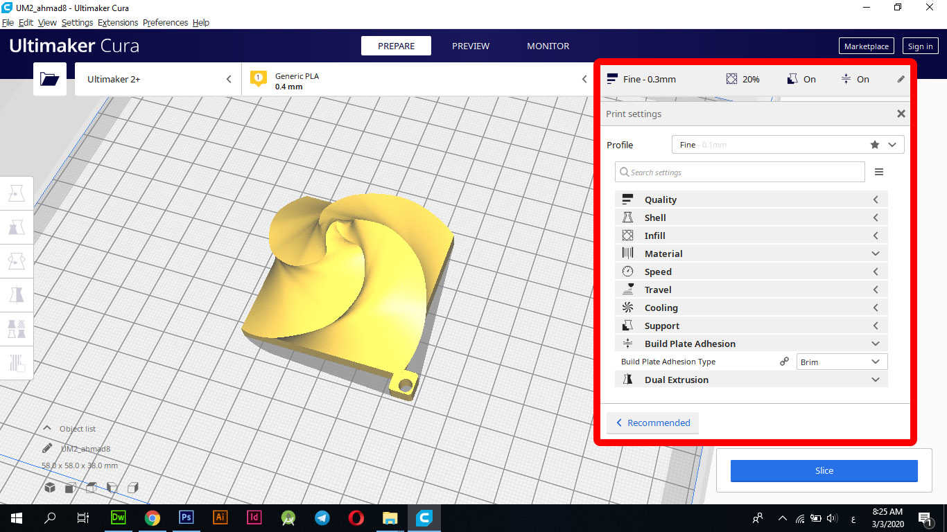
In this step I worked on "Cura" software to adjust print settings and more things about that.
I opened my design through the folder icon that appears in the image below inside the red frame at the beginning of the rectangle on the left side, then in the second step I selected the type of machine Ultimaker 2+ "as it appeared in the rectangle in red in the second section, in the third step I chose The material type is "PLA 0.4" as shown below.
These following settings I use to define the speed and level of accuracy as well as more Settings of the first print head (PLA):
It took 2 hours and 4 minutes to finish printing.
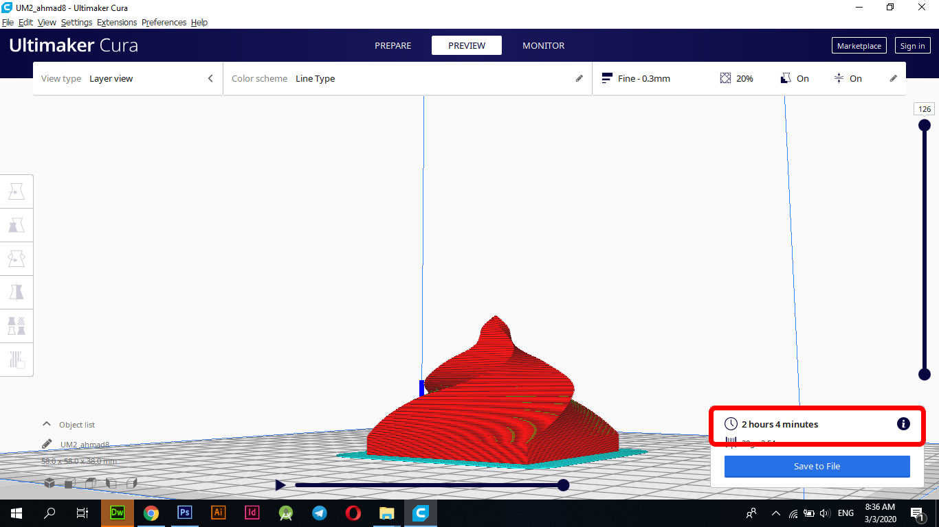
It took me two hours and 4 minutes to finish printing, and then I saved the design. I will produce the design in ".gcode" format, which is the format that 3D readers are available to read and can handle.
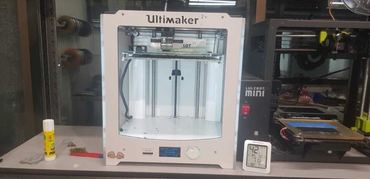
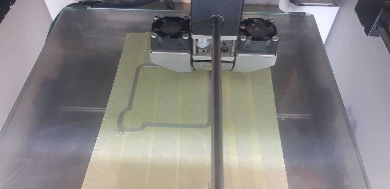
Ultimaker 2+
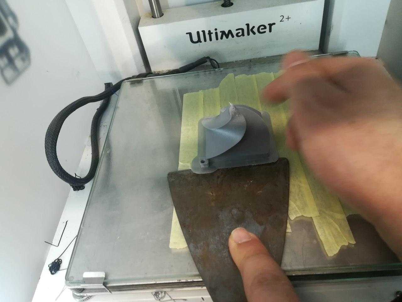
To print my file, I used "Ultimaker 2 +" as it is considered the most suitable for my design achievement. I used "PLA" material which is for 3D printing, I used adhesive and super glue and attached it to the surface of the printer to ensure it is removed easily after the printer is finished From the design of the shape, and then I transferred my design to "SD Card" and I inserted it into the printer and I began to specify the material used which is "PLA" Also I chose my design and I gave it to the printer, we note these steps mentioned above all in the pictures attached below.
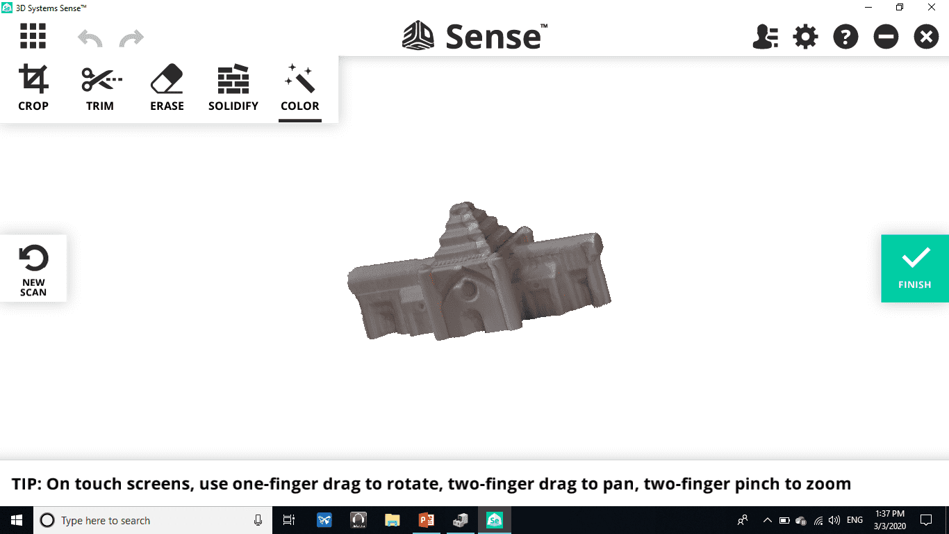
3D Scanning Sense
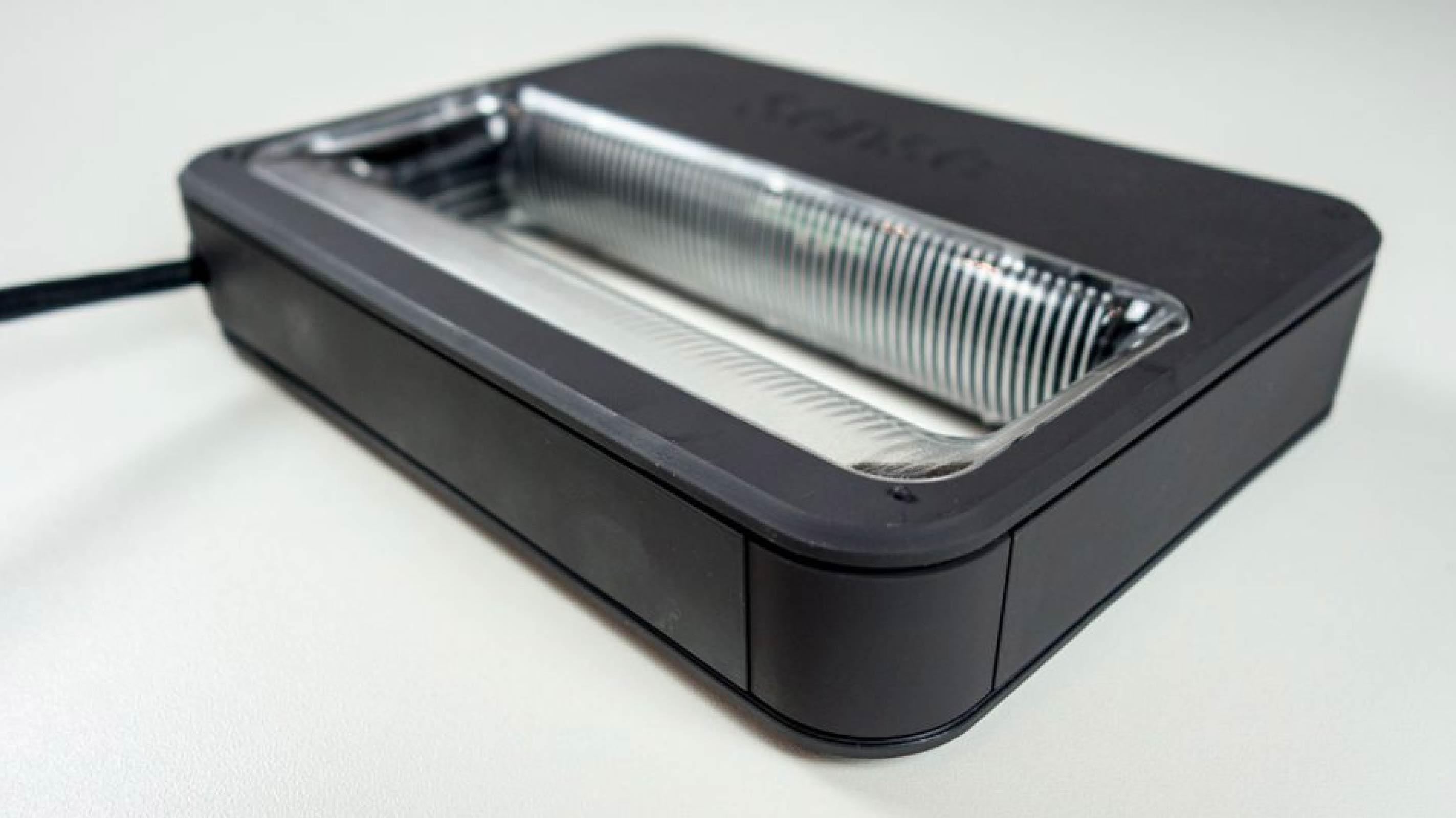
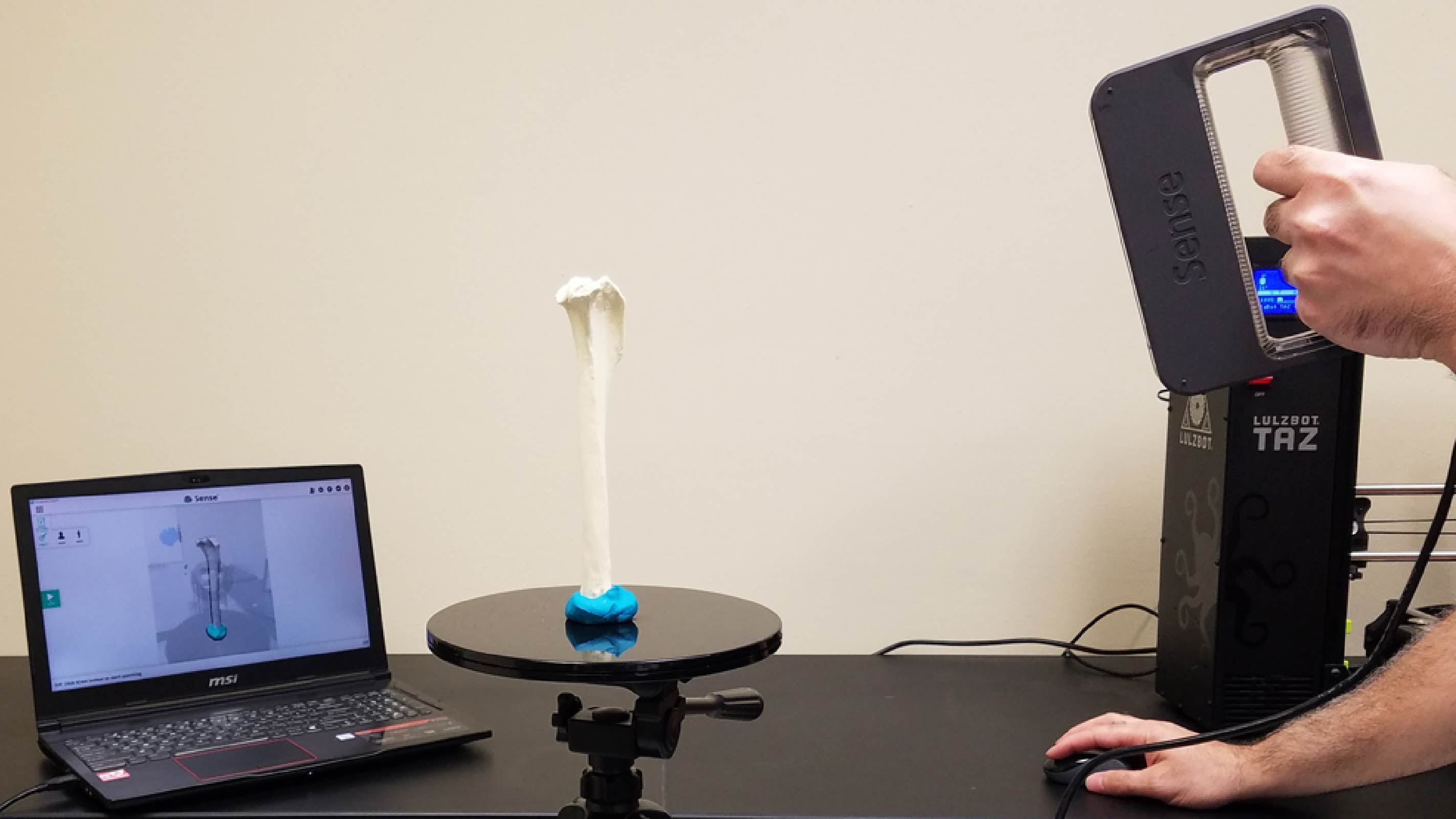
I used the 3D Sense tool to add a stereo to the program. How it works: I connected 3D Sense to the computer through a dedicated link and opened the Sense program, which is the program that connects it with the tool that will make an imaging of the stereoscope that we want. After connecting them, we put the stereoscope that we want to clone in a good place, that is, it is far from Colors and one color where imaging of the holographic is better and easier, we grab the instrument and direct it towards the exact object and start the rotations around it in a "360" degree so that we cover all the parts. In fact, he used The Solidfy tool included in the program was repaired for invalid parts and the result was excellent as it fixed several deformations.
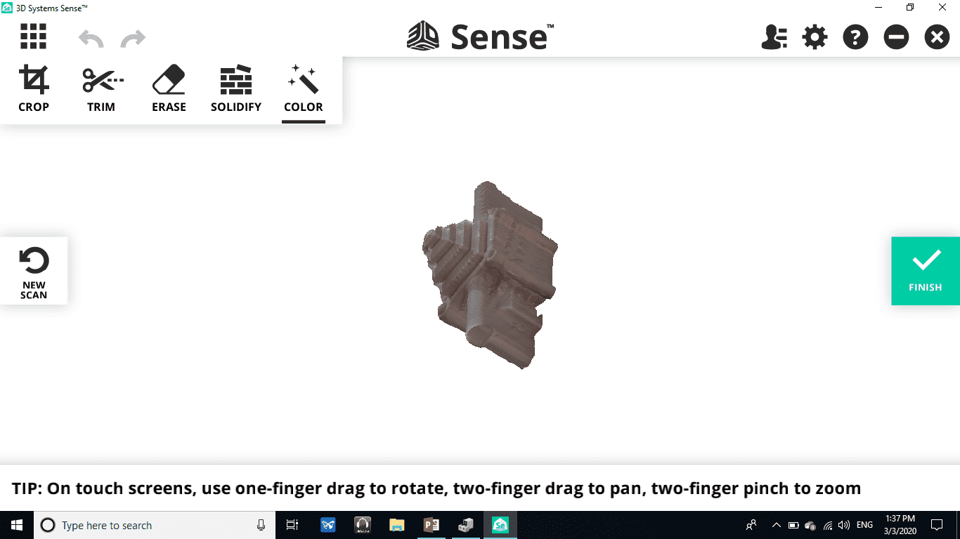
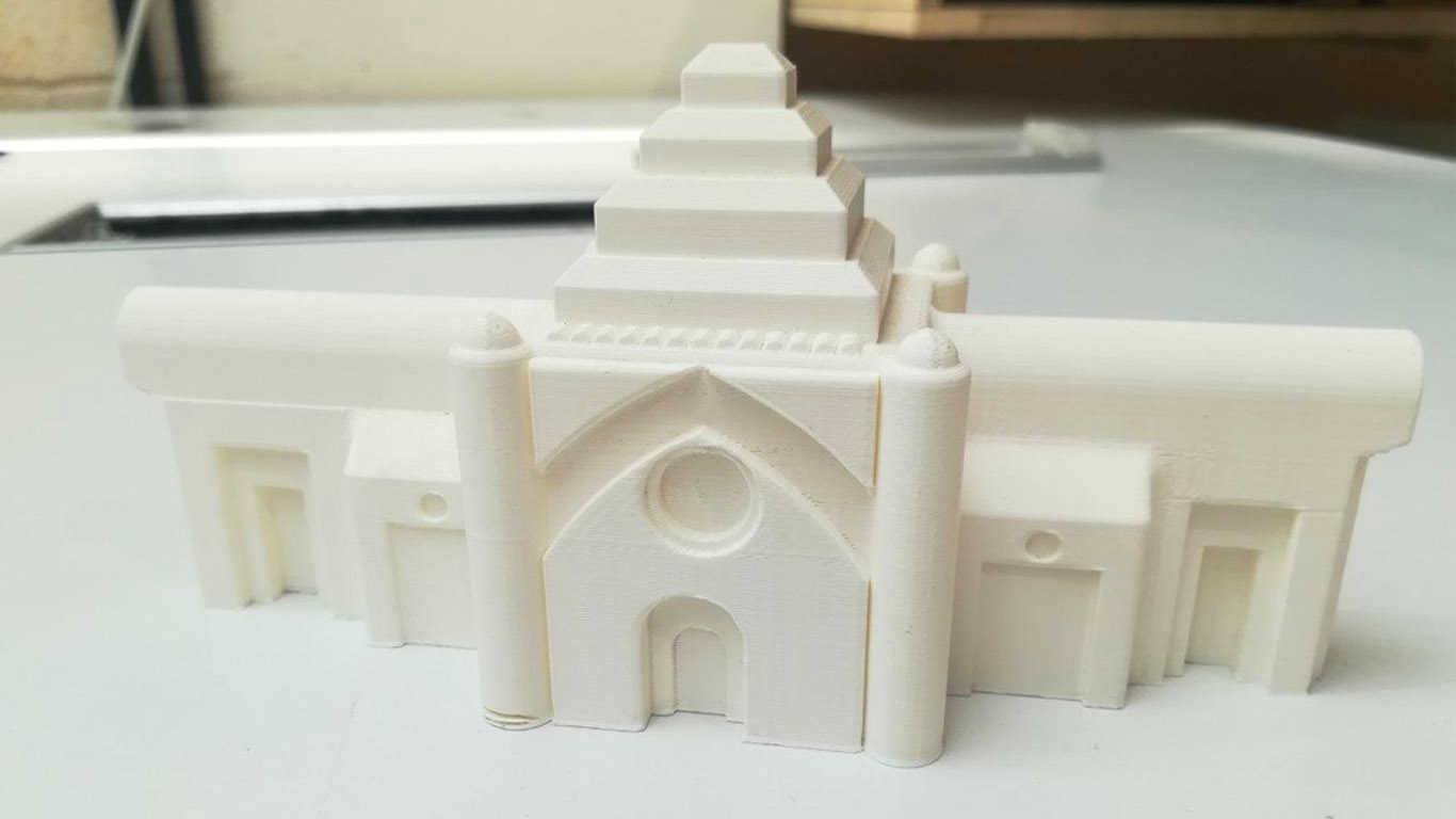
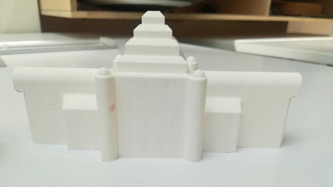
Through the 3D Scanning device, I redrawn the design flip before, and indeed, through the "3D Systems Sense" program and the "3D Scanning" device, the castle was photographed and shown in a similar form as a "true copy", but what caused the design distortion is the accuracy of the device as The accuracy that the device is able to capture is not satisfactorily high, but I tried to show designs of all dimensions in the best shape and I have this shape in the following image.
Files - Open Source
3D Printing FileGroup Assignment