Computer-Controlled Cutting
This week we learned the basics of handling and cutting with a laser and vinyl cutter.
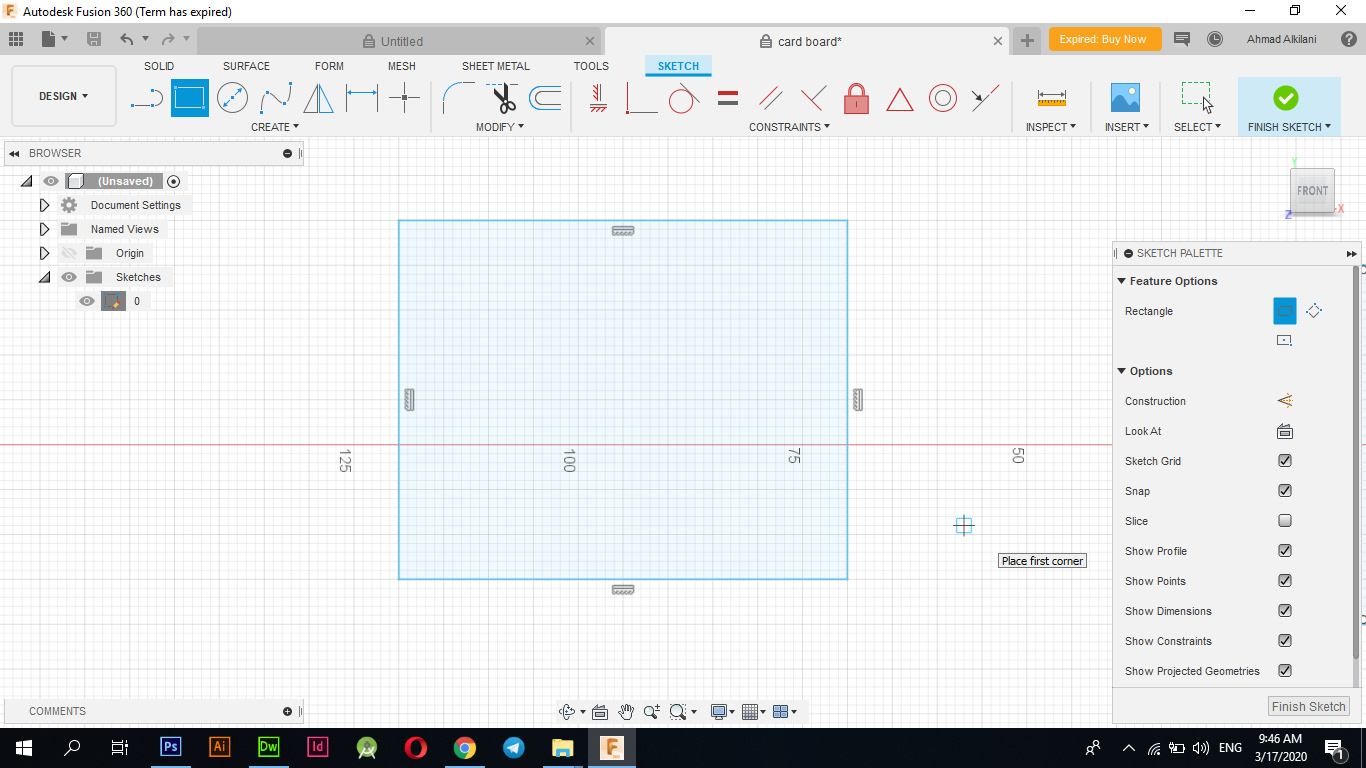
Design By Fusion "Parameters"This week I will be designing a simple card in wood to be installed in several different shapes, first I worked on the Fusion 360 3D Graphics program and created a rectangle 4cm high and 5cm wide.
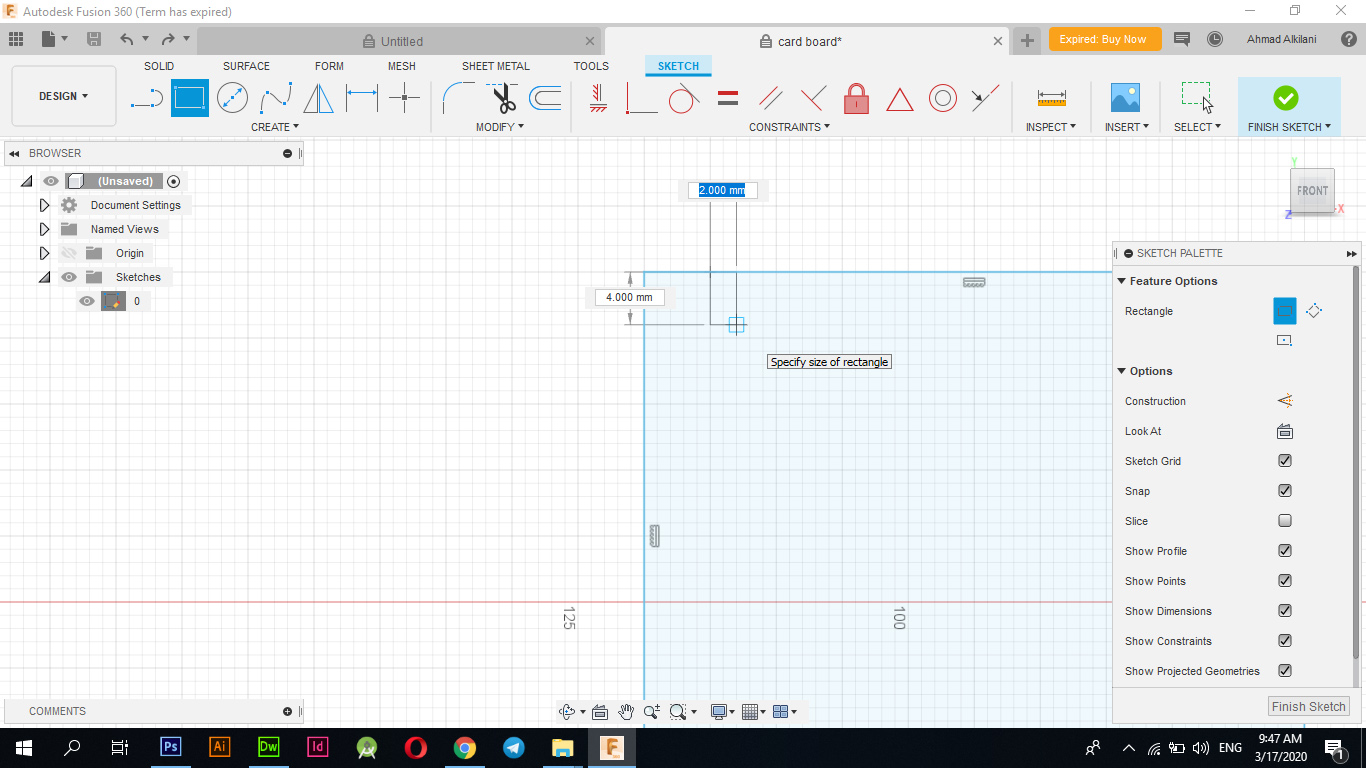
Then I started creating rectangles with different heights along the board. I created five rectangles on one of its first sides with a height of half a centimeter, the second with a height of 1 cm and the third with a height of 2 cm as shown in the following pictures.
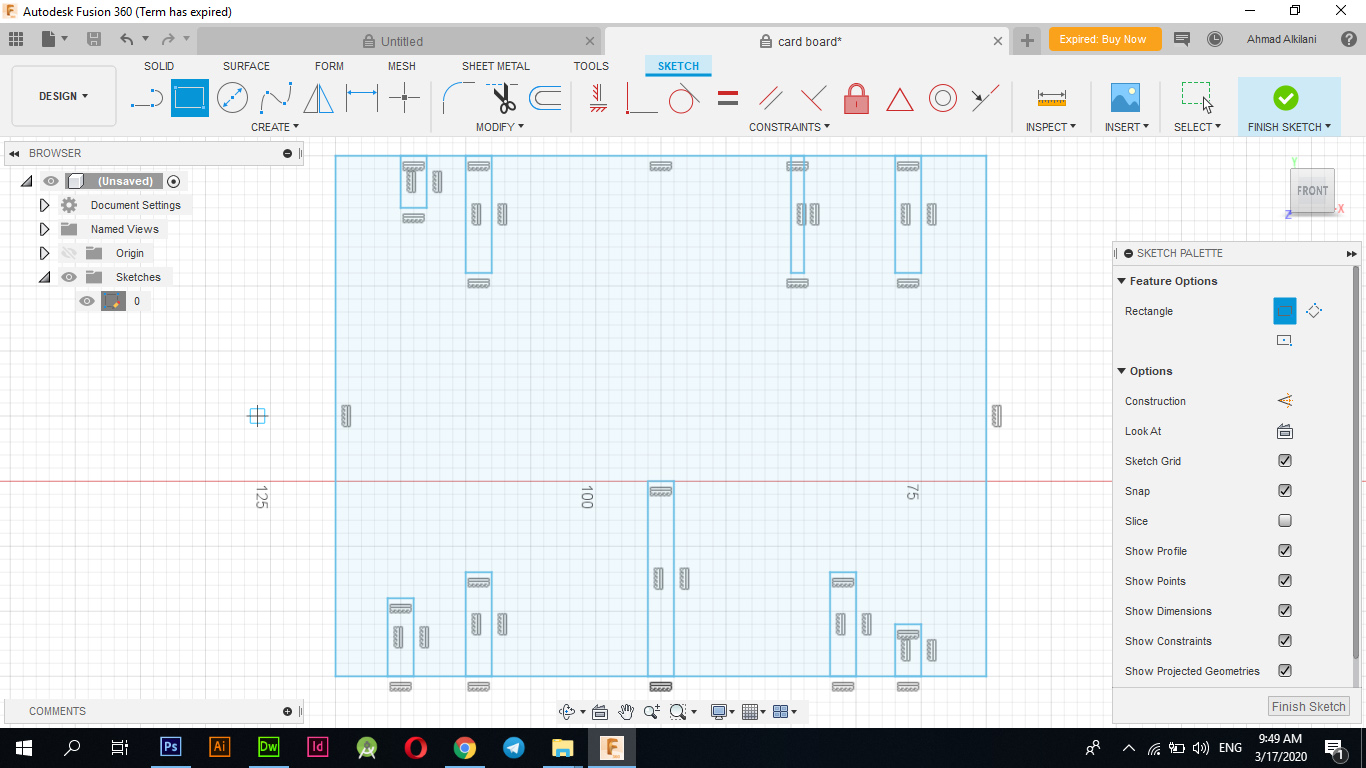
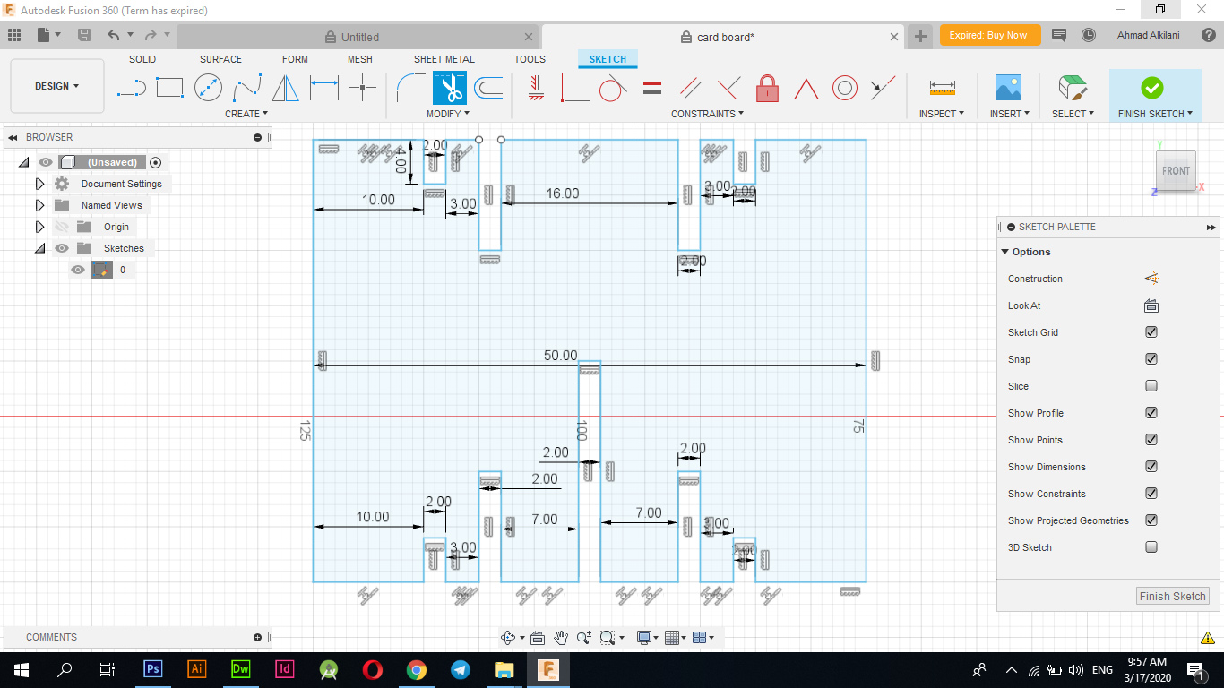
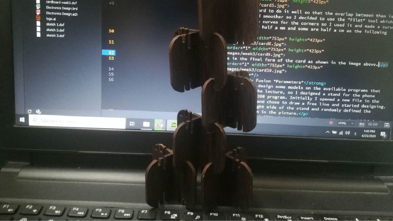
The following figure shows the number of rectangles and their location on the card that I will be designing. I used these interferences to take advantage of their installation on each other and exit in several forms of them, where the cards can be attached to each in each rectangle or slot that I created, which may give me exit in more other forms.
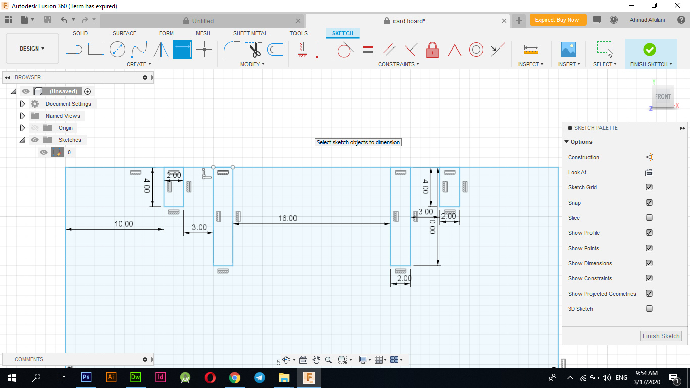
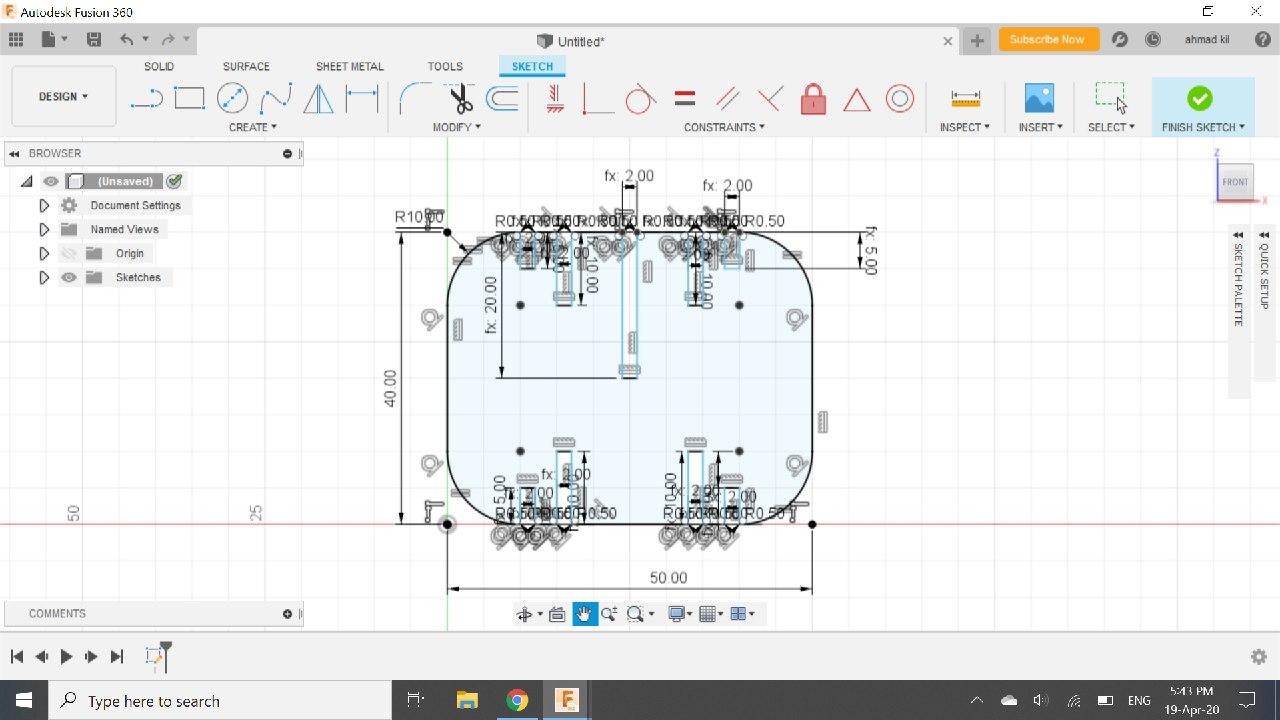
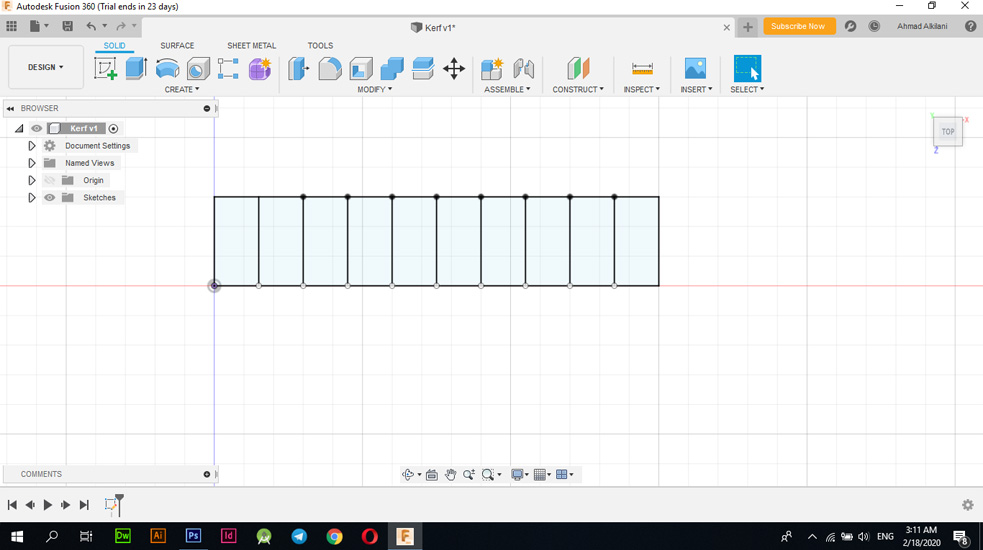
I also pictured the following image and it shows the distribution of dimensions between the slots over the card that I will design to distribute the distances evenly between those slots through the Dimensional Tool as in the image.
The next scroll shows the final distribution of the rectangles along the card.
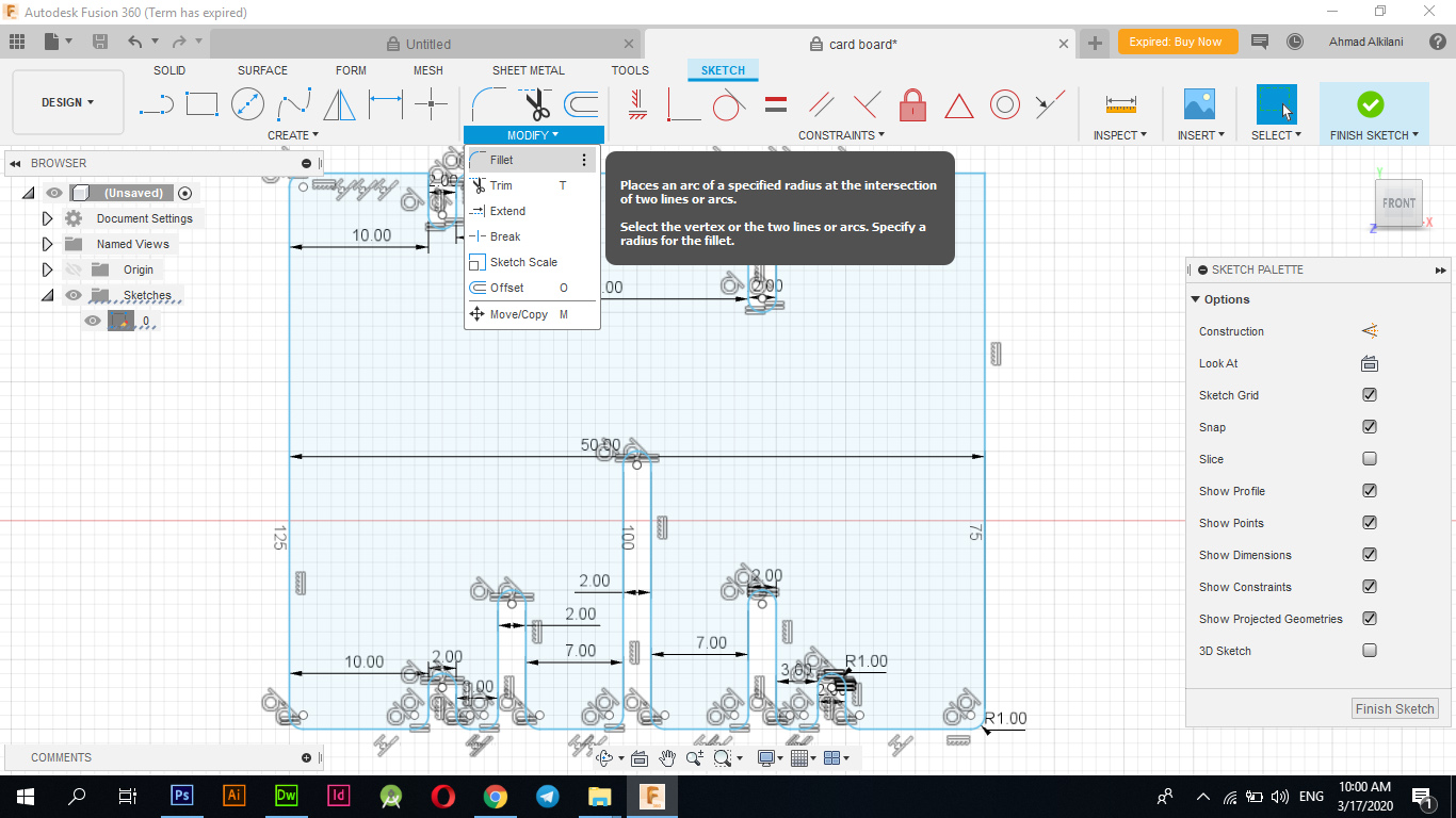
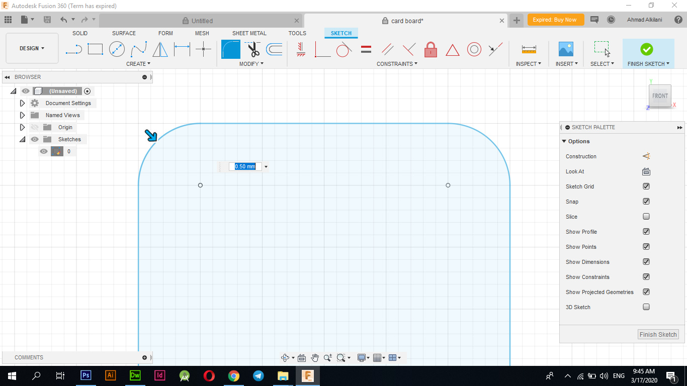
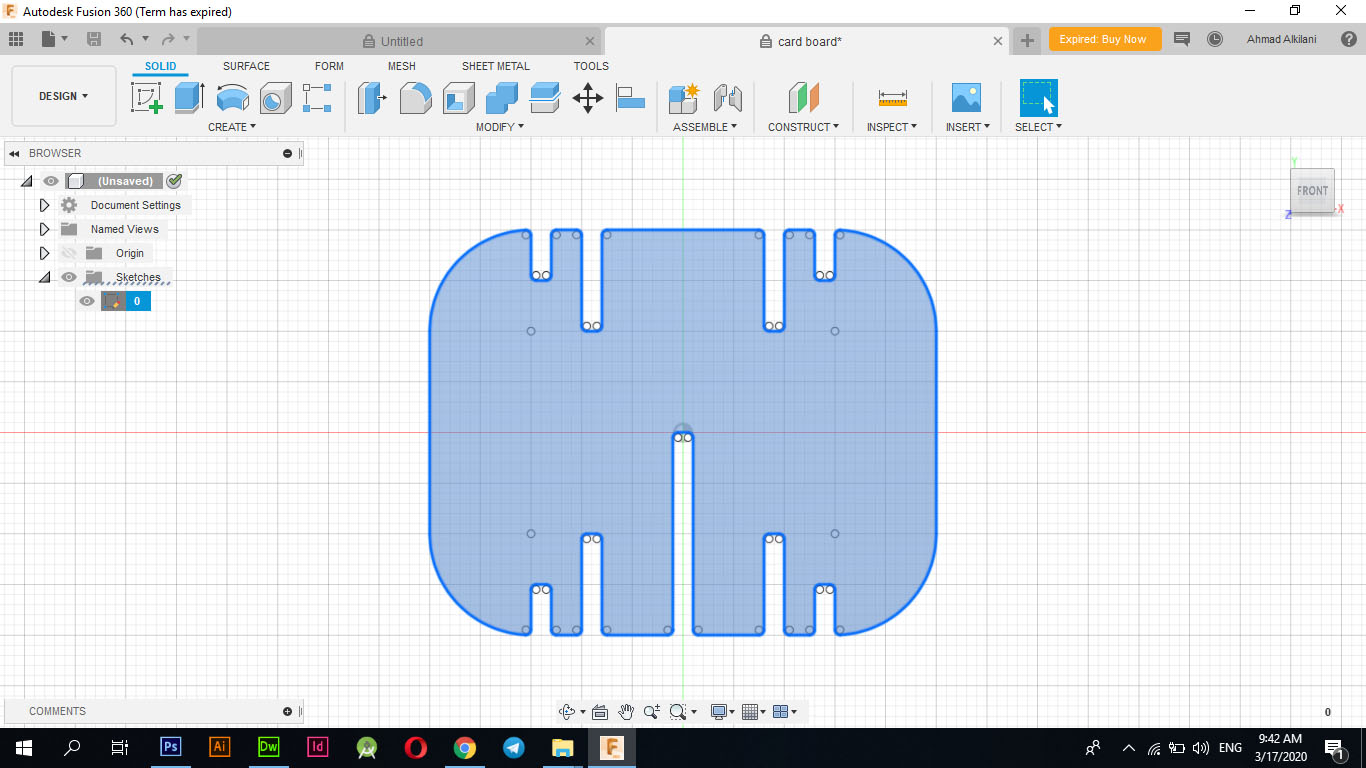
I tried very hard to do it well so that the overlap between them is better, faster and smoother so I decided to use the "Filet" tool which enables me to make curves for the corners so I used it and made a curve for the corners by half a mm and some are half a cm as the following figure shows.
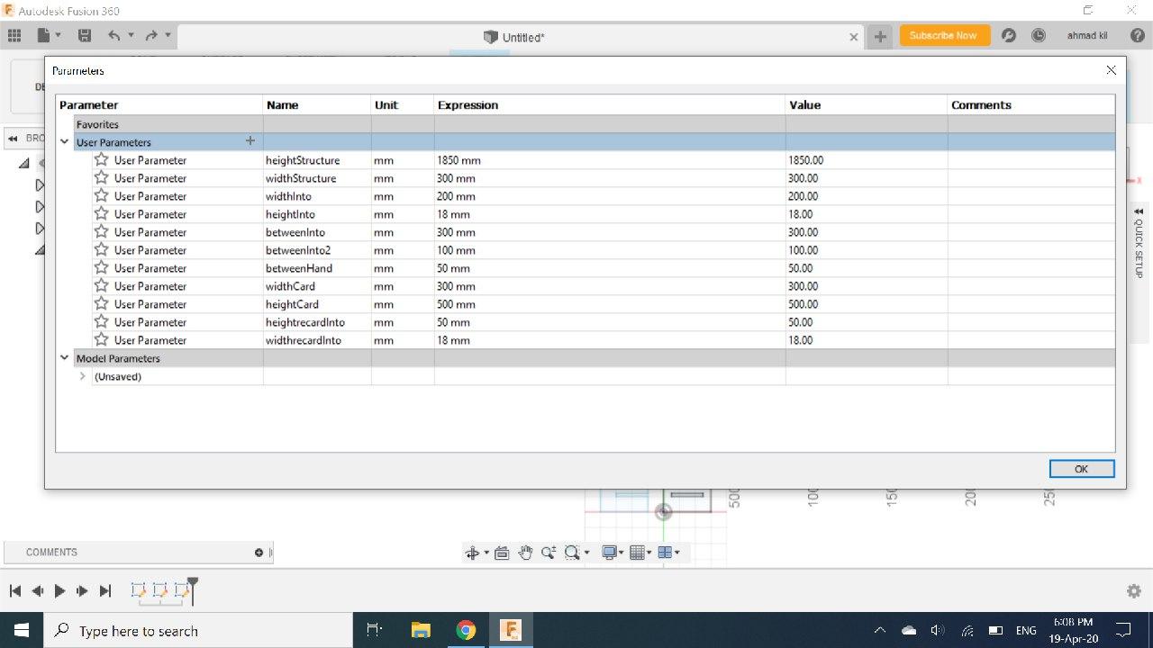
To convert the shape to "Parameters" you need to link all sides between them so that if you change the size of a side that changes with the other sides and the design remains the same, the following images show the names of the tags that you choose and the size of each of them can be accessed through the "MODIFY - Change" tab. parameters "Through the" + "sign have included more tags for this design.
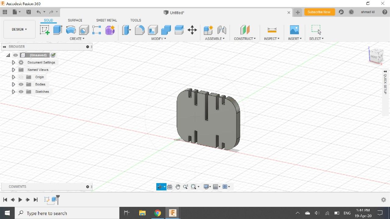
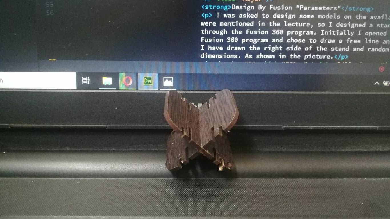
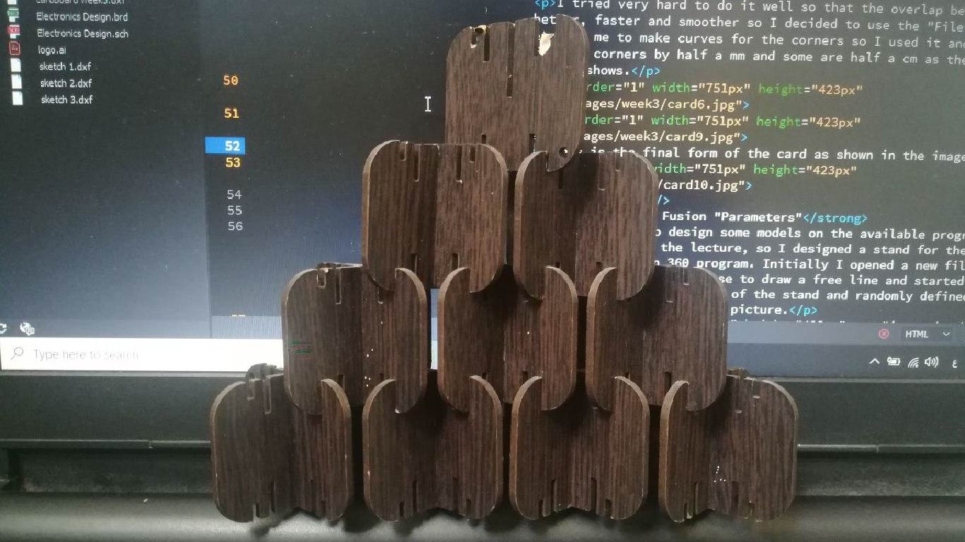
This is the final form of the card as shown in the image down.
Now I moved the design file to CoreDRAW and set some program settings to prepare the file for cutting on the machine, where I changed the color of the external design to pure red where the machine recognizes that red is the location of the cut that will be cut on and therefore if we want to cut on a specific plate The color of the line that will be clipped must be changed to red.
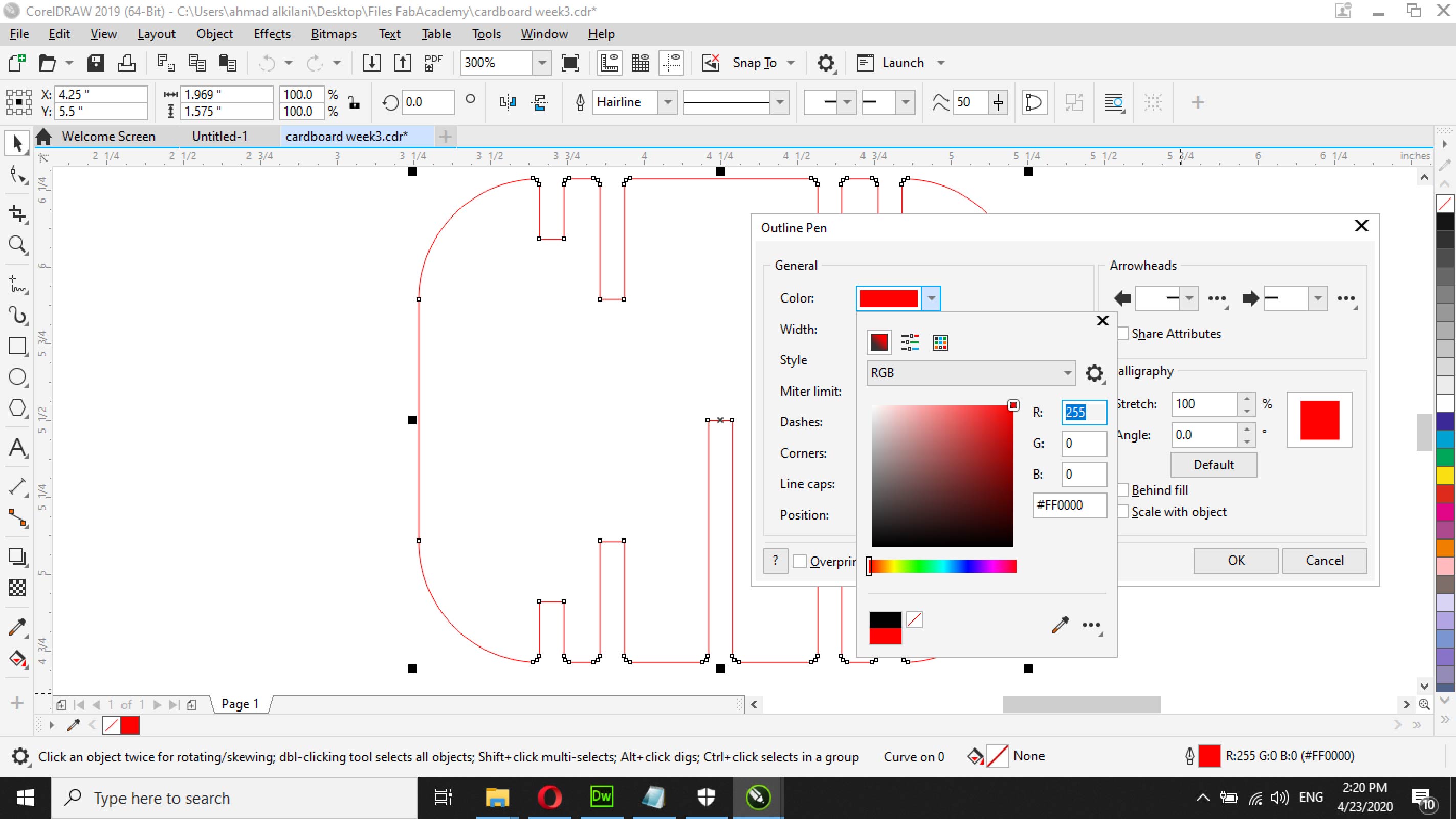
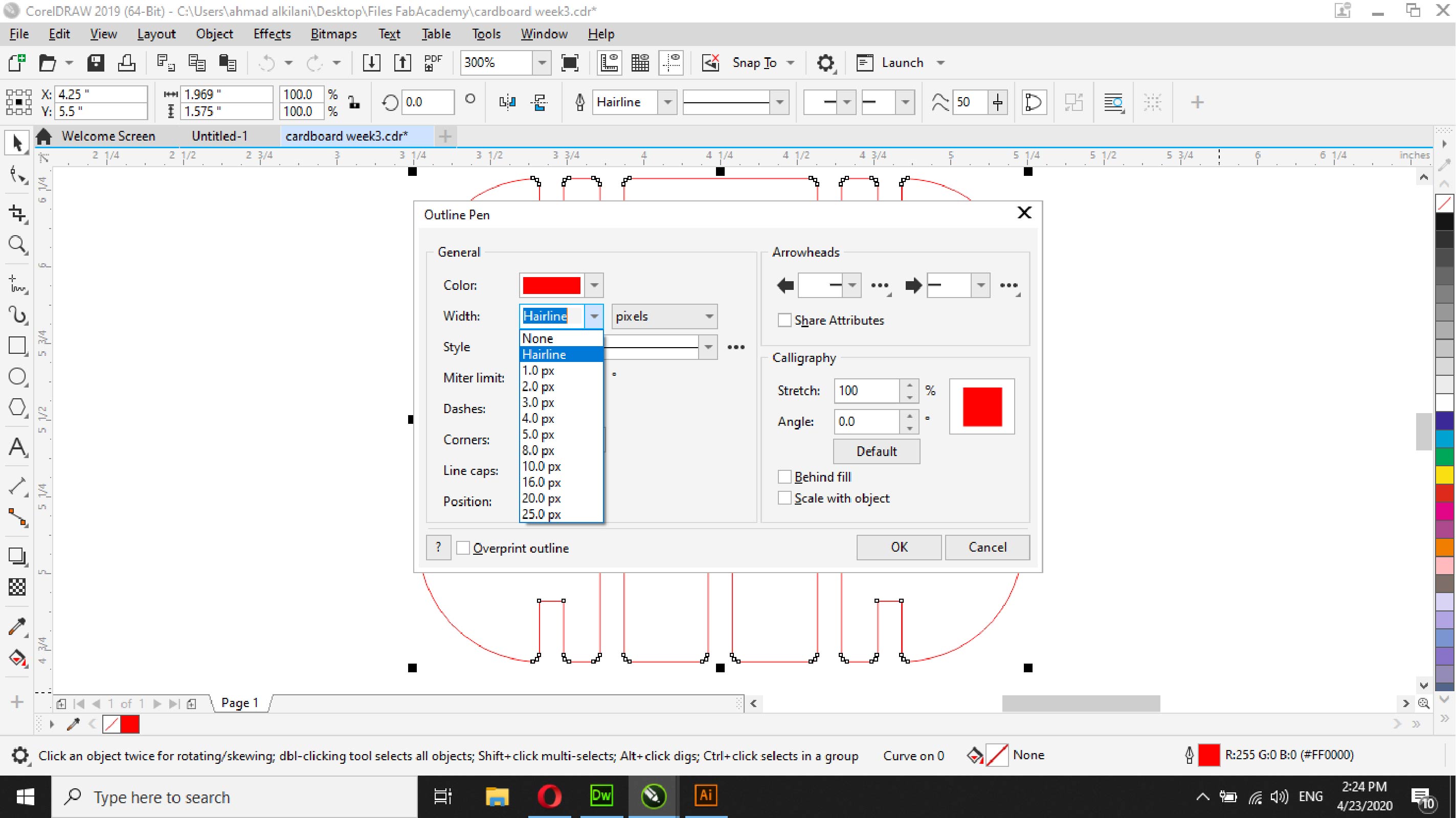
Also we have to set the lines as "Hair Line" for the machine to be defined as the cutting borders or as the line that will be followed by cutting during the process.
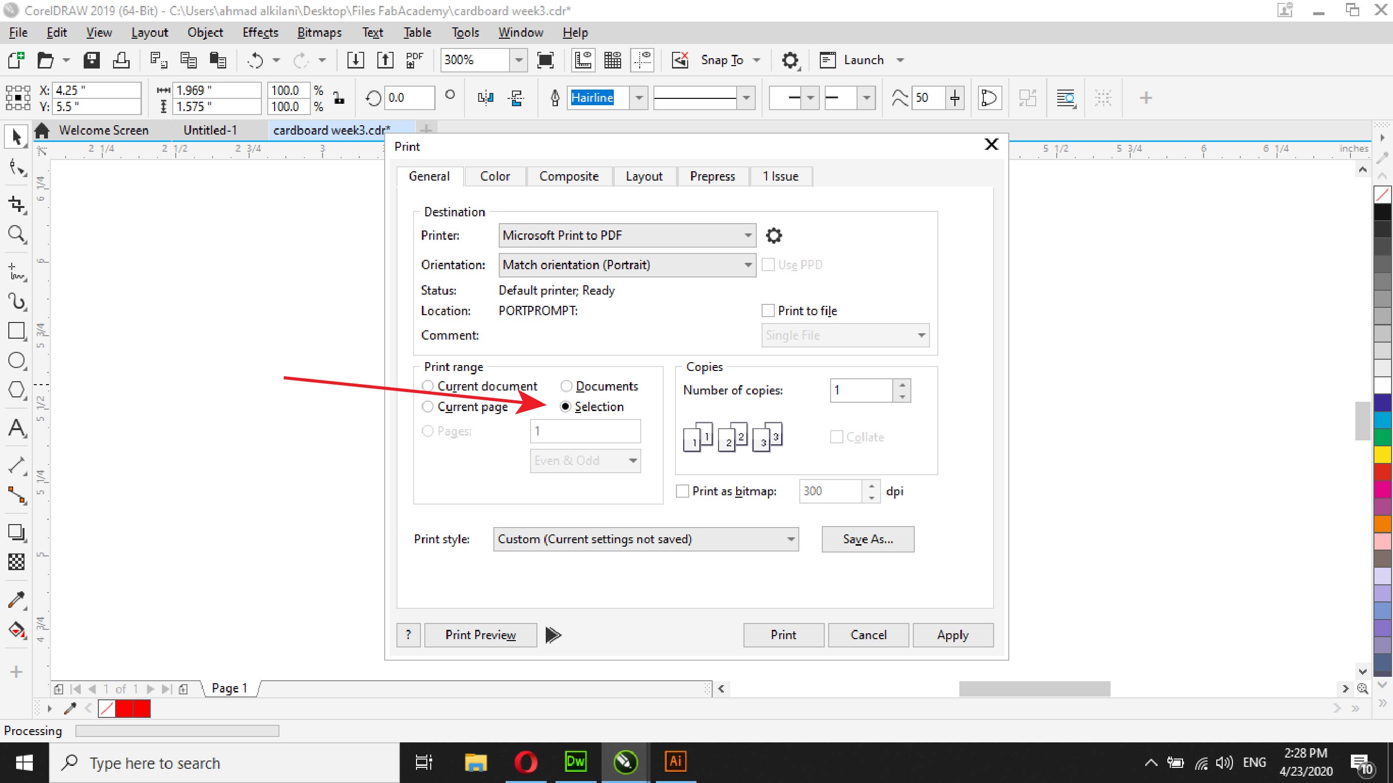
After completing the last two steps, I moved to set the print settings. By pressing the "Ctrl + P" buttons, I moved to the print panel, where it contains several tabs. What interests me is the "General" tab, which I will select on the "Selection" option, which will recognize the elements that you have selected. However it will be cut only or the rest of the unspecified parts even if they are in the same file will not be cut, the bottom line is that this option will only cut the parts that we selected.
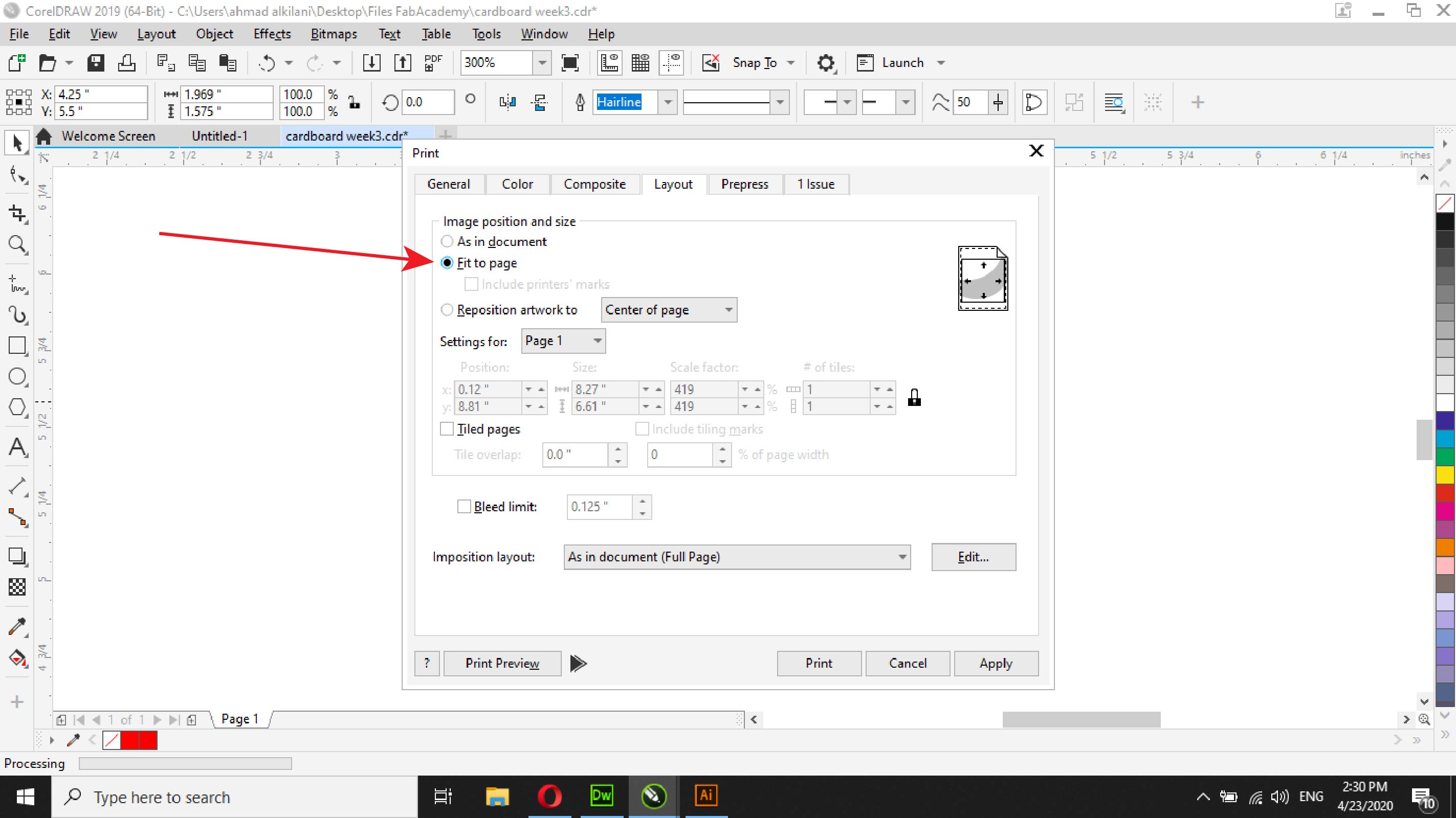
Also in the "Layout" panel we will select the "Fit to page" option. This option will make the page match your design and will not increase or waste more panels.
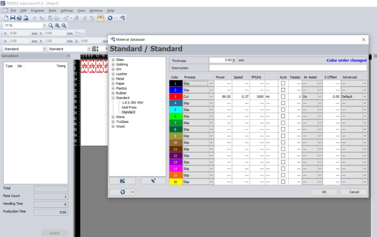
After finishing, we choose "Print" or transfer it directly to the "Job Control" program, which is the program that gives the printing order to the laser cutter machine. In this program, the shear place is set on the board and the required values are set such as the size of the plate thickness and others and then we press "Ready" "To begin the cutting process.
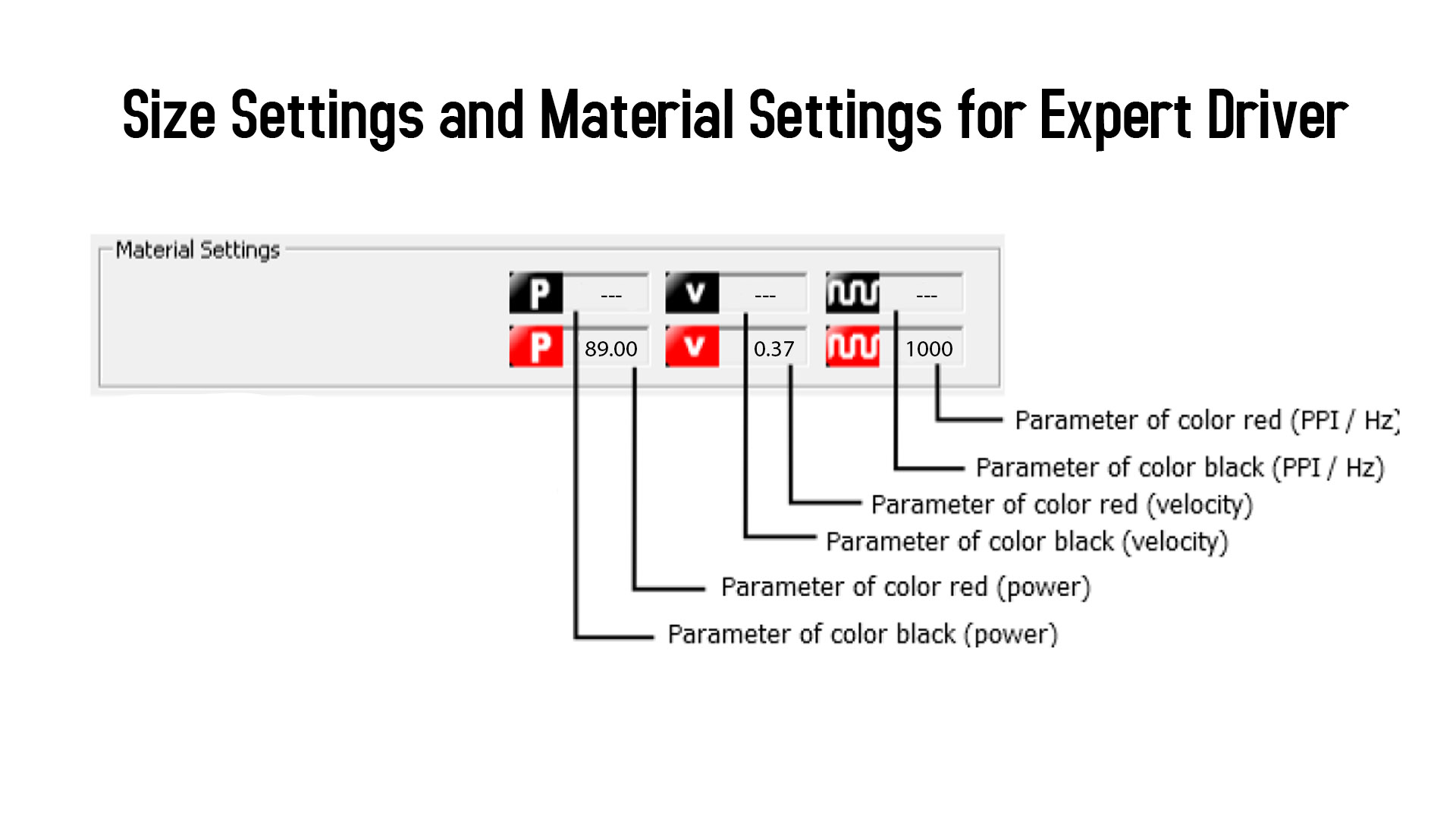
In the image below, I have chosen Cut, which is the red color that the machine recognizes as the cut command. I have chosen the speed, heat and thickness of the wood to cut.
To learn more about how to use Job Control and adjust cutting settings, you can read the following book that explains how to use Job Control and how to use a laser cutter machine to cut, engrave and engrave, Click Here
To learn how to choose the correct proportions of the machine, you can review the following file that I used to find out the correct proportions of the machine in terms of speed, temperature, thickness of panels and how to use those ratios with it. I have read the following file, Click Here
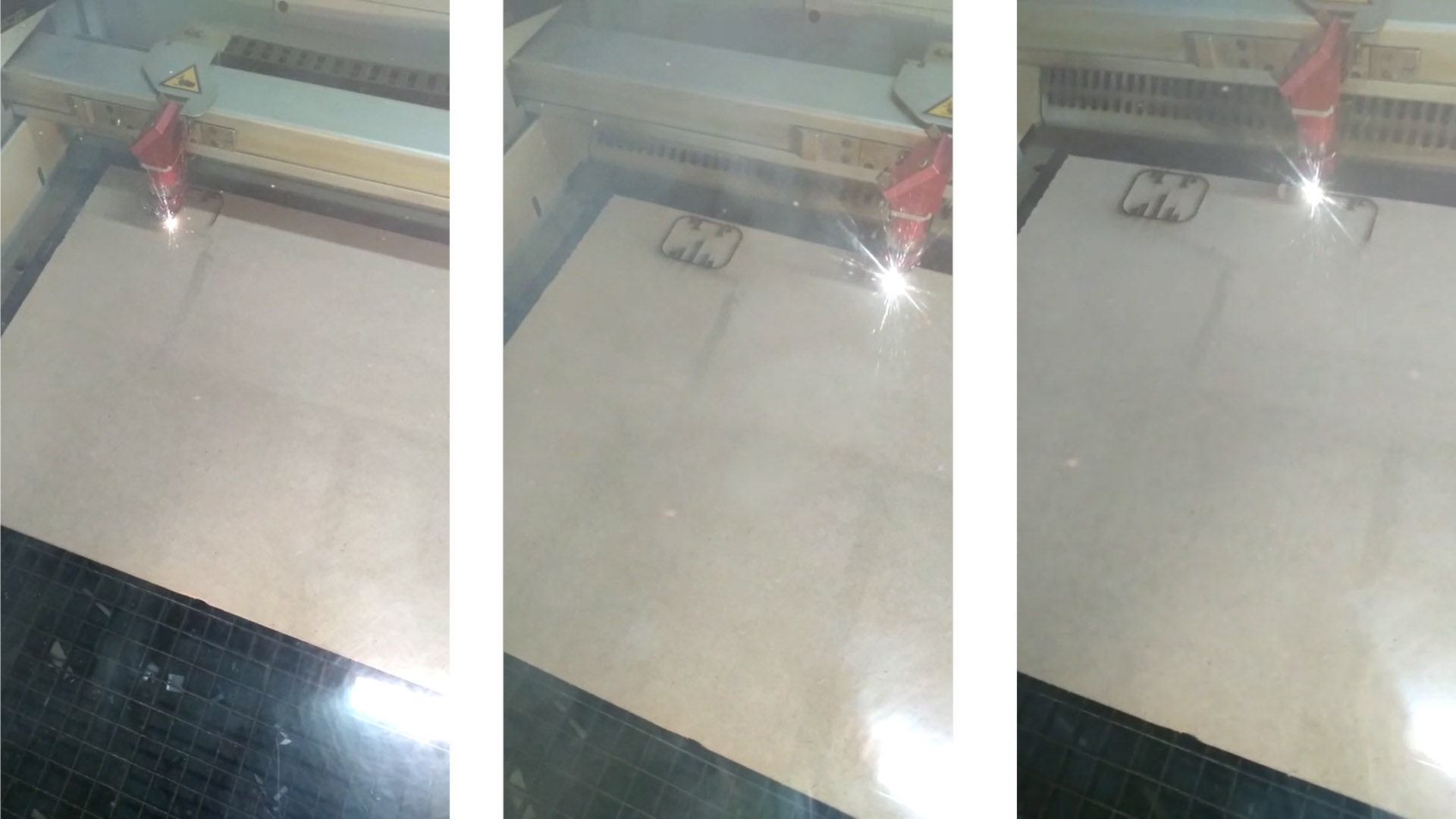
The pictures below show the cutting mechanism with a Laser Cutter.
Kerf Account
In the lecture, we were asked to calculate the Kerf for the cutting operations that we perform. In our group, we distributed the tasks, and each of us has been distributing a type of wood or acrylic. I chose the 5mm wood, and I calculated the kerf for it. Follow the method.
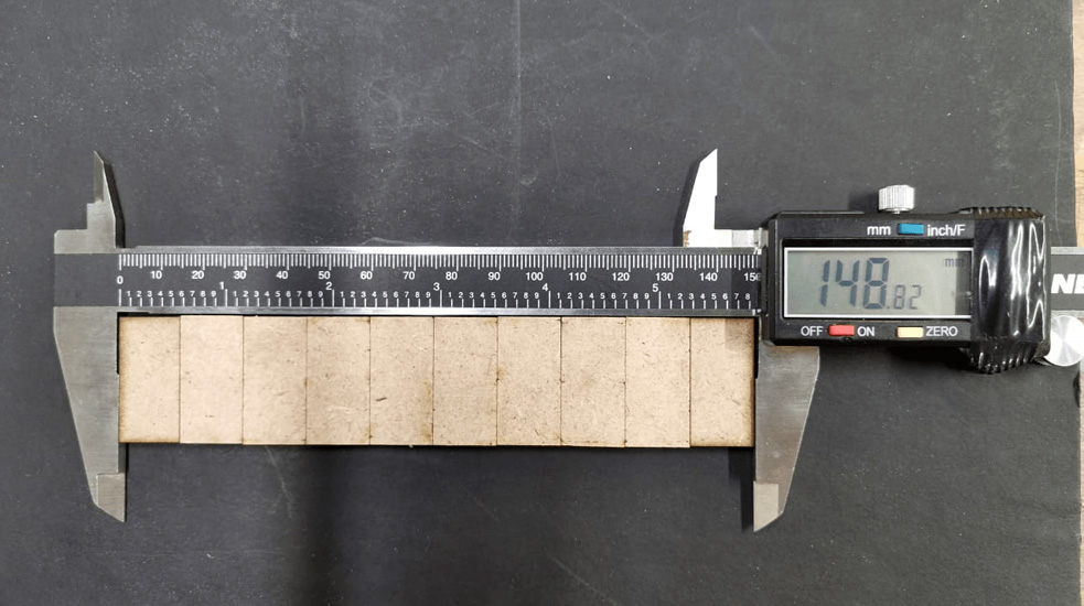
Initially I designed a rectangle of 150mm width and 30m length, then I saved the design and moved it to “CorelDRAW” then to the laser cutting machine. When finishing the cutting I calculated the deficiency caused by the laser cutting during the wood burning process as shown in the picture The decrease that occurred.
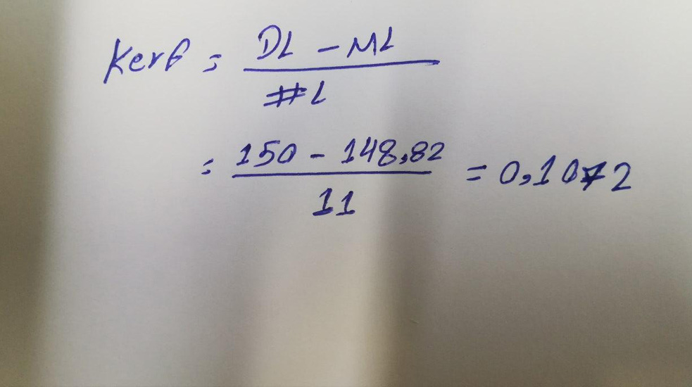
Through the law in the paper, I made the subtraction, I subtracted the original size "150mm" from the measurement that resulted after the cutting process, and then I divided the result of the subtraction process by the number of lines contained in the design and produced I have a number ...., see the law and the calculation process in the image next.
Vyinl Cutter - Des By illustrator
At this stage, I designed my own logo through the Adobe Illustrator program, which is a program dedicated to drawing nudes and Victor and many other types of design. I initially made a visual feed by looking at websites that contain many logos that you can quote ideas from or take and modify them , But I chose to take a visual feed and start designing my logo through Adobe Illustrator. In Aldaba I created a file and set the color mode in the "CYMK" format, which is recognized by most printers.
Through the "Pen Tool" I started to draw my motto and design some curves and letters that you can see in the following pictures.
Therefore, you have increased the number of shear times. Also, on this tab you must choose the type of printing and cutting. If you do print and cut, you must choose the first option "Print and cut" and can choose a standardized either cut or print.
In this step you have to choose the outline of the sternum and set the size of your logo or design.
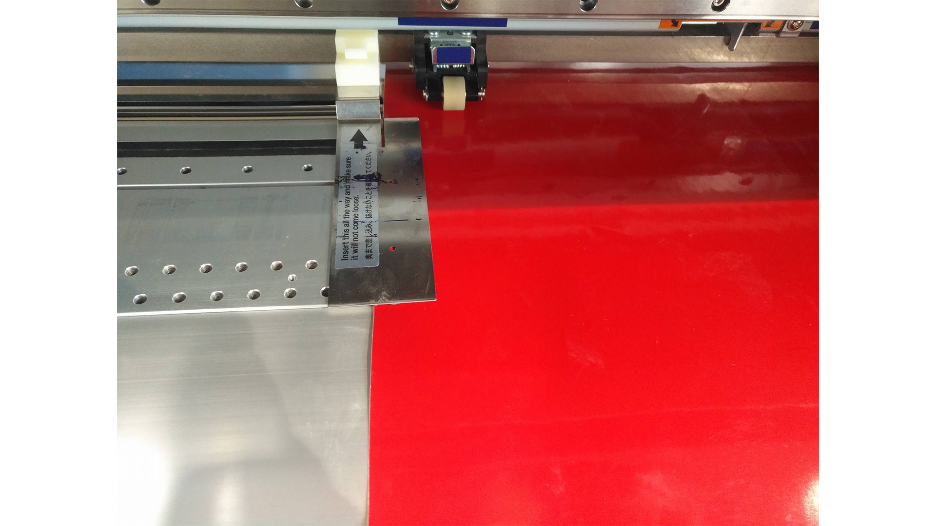
To start the cutting process, I installed the red color roller on the machine to start the cutting process. The roller is installed by placing it on the wheel rims placed in the machine to give the machine the freedom to return and introduce the roll to ensure that no error occurs in the printing and cutting process.
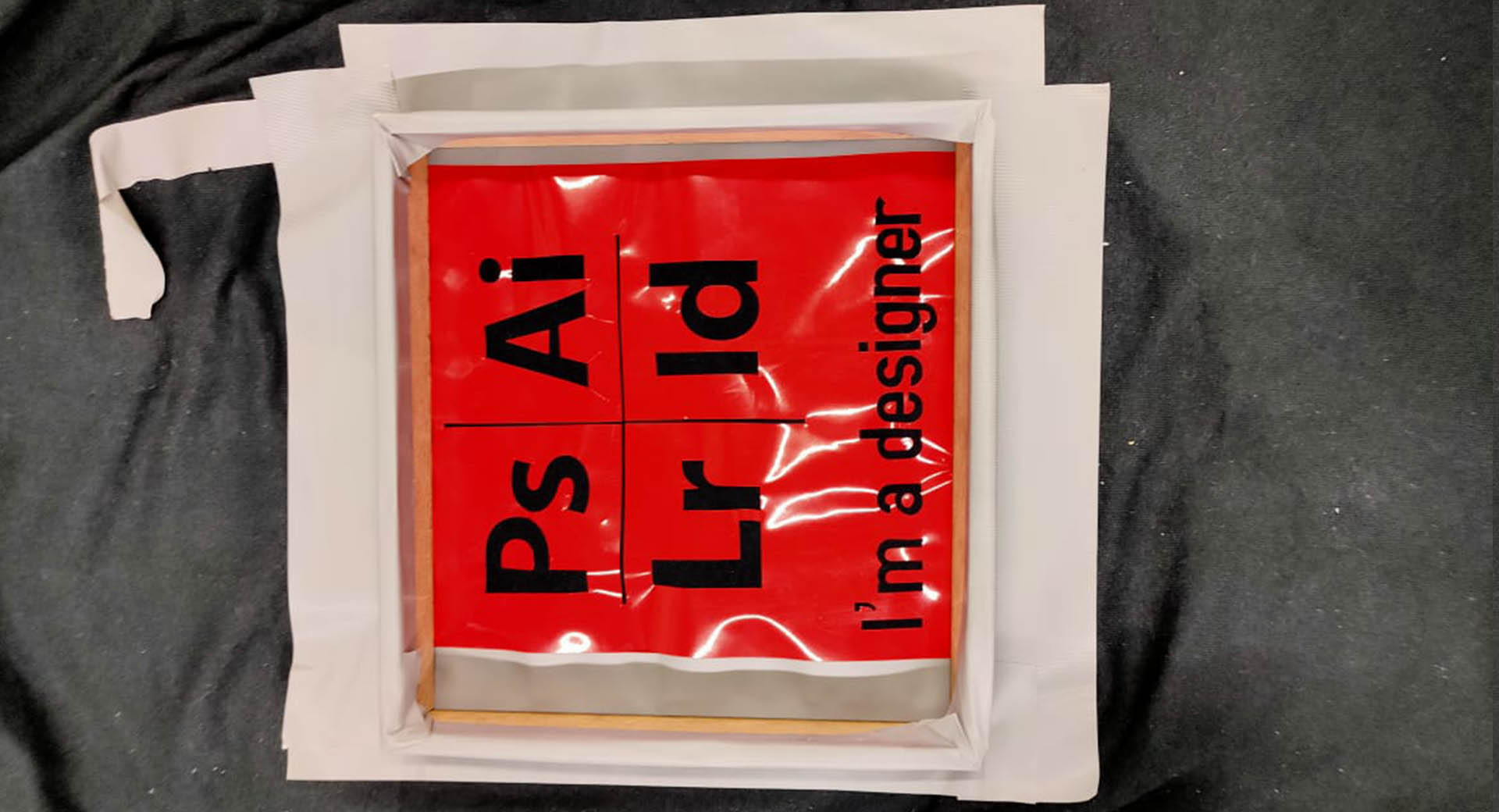
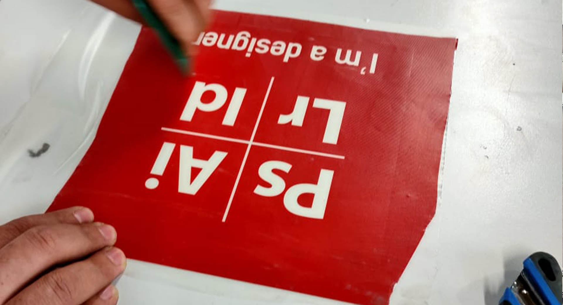
After completing the cutting process, we dump the image from the unnecessary part in the sense of deleting all the things surrounding the part we want and this following image shows the process, I used this image from Wild Card Week because of the loss of the original image of the logo that I designed this week.
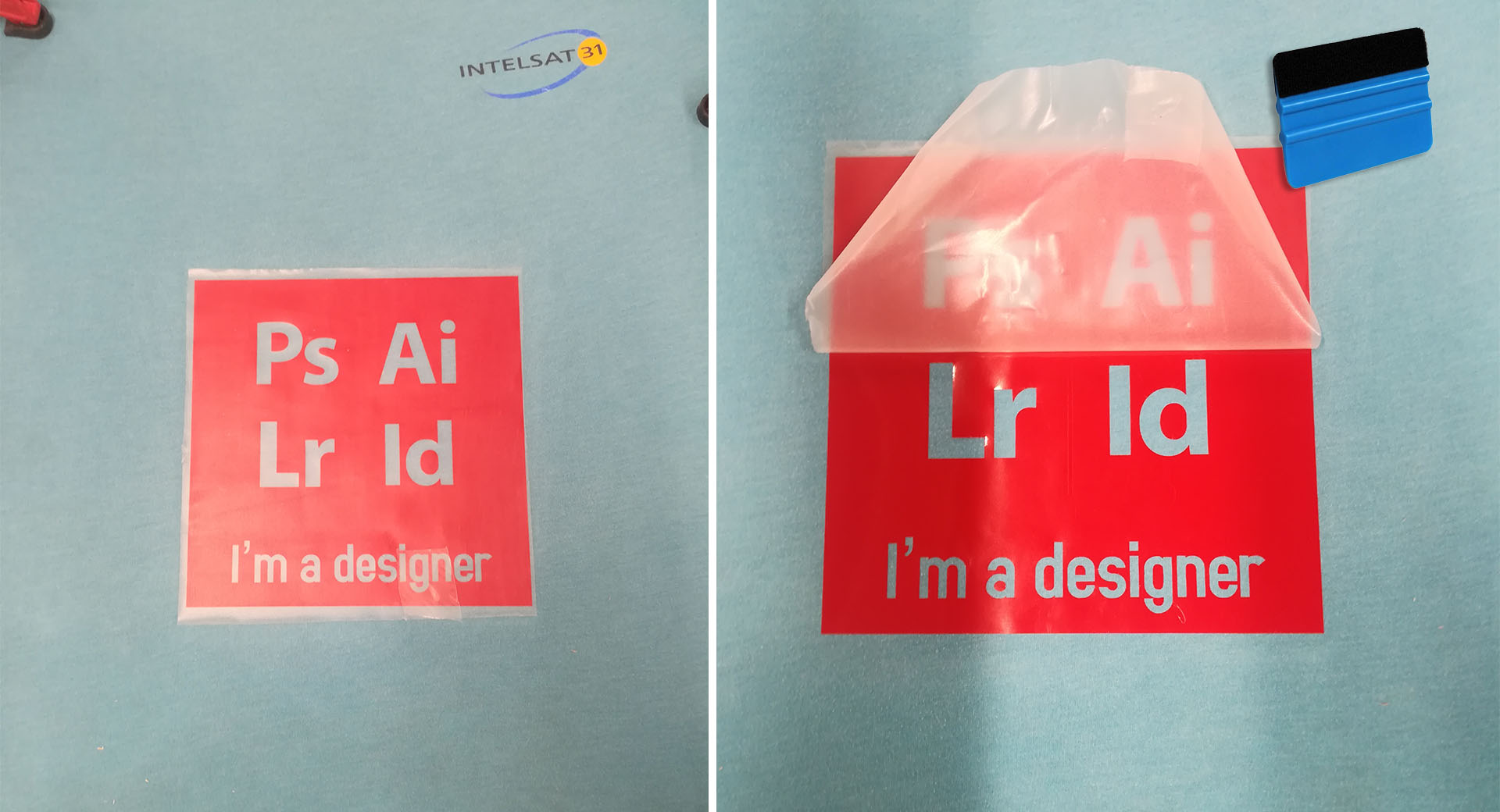
After unpacking the image, we also put the adhesive substance through which the poster, image or logo that we designed can be installed and pasted in the appropriate place. The following pictures show the correct adhesive mechanism.
The pad is used, which is a slightly flexible piece through which the sticker, logo or image to be printed in the designated place can be compressed, making the poster last longer and allowing it to stick stronger and stiffer.
Eventually I got this logo that I glued onto my laptop
Problem
After completing drawing the logo, I wrote it and saved it as "pdf" and then took it to the printer "Roland BN-20" and through the "Versa Works" program I started to set the cut and print settings in the following image showing the number of cut times "4" times, I increased it to 4 because I had a problem in The problem is not to cut the design so that it can be emptied as shown in the following image The problem of not emptying the logo easily while I had difficulties until I got to
Files - Open Source
Card BoardKerf
AK Logo
Group Assignment