Input Device
This week we had to test with different input devices using a board that we built on our own, I created an electronic board that works like an Arduino by using some parts that meet my need for this week. My experience was centered around sensing the movements of people or things regardless of what they were and creating a specific reaction, Input devices are used to sense the environment around us, you can sense and track different parameters using sensors and have them create a certain action based on that input.
This week, I designed an electronic board that meets the requirements of this week’s experiment. The main part of this week’s experiment was the sensor and the motor. I used the sensor as a main part, where this sensor is the input part.
How is that?
Through the sensor, I can perform the process of sensing the movement of people inside the space and the space in which the sensor can capture the movement of a person. I used the sensor and made it the main center to give commands and transmit them to the engine, where the sensor senses the movement of people, and in this case we can get the input process where that The sensor has done what indicates the mechanism of sensing the movement of people and is classified as an input device, as the sensor processes the commands inside it, meaning that the person’s movement is what gives him the opportunity to be an input device.
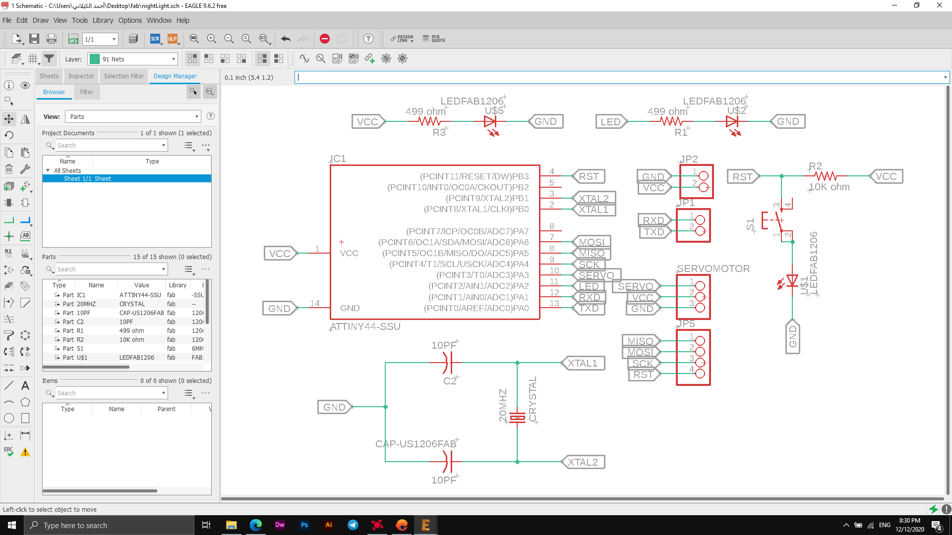
The following picture shows the parts and the scheme used to create a custom electronic board for this week, the picture shows all the parts that will be used and the ports assigned to them, where I will install the Ultrasonic sensor and Servo Motor. I've used an ATtiny44a controller, and it works. I connected the parts to each other through the Eagle software as it didn't take much time, I used high quality settings as the thick connecting lines.
The image above shows the final connection process, as it shows that all lines were connected to them.
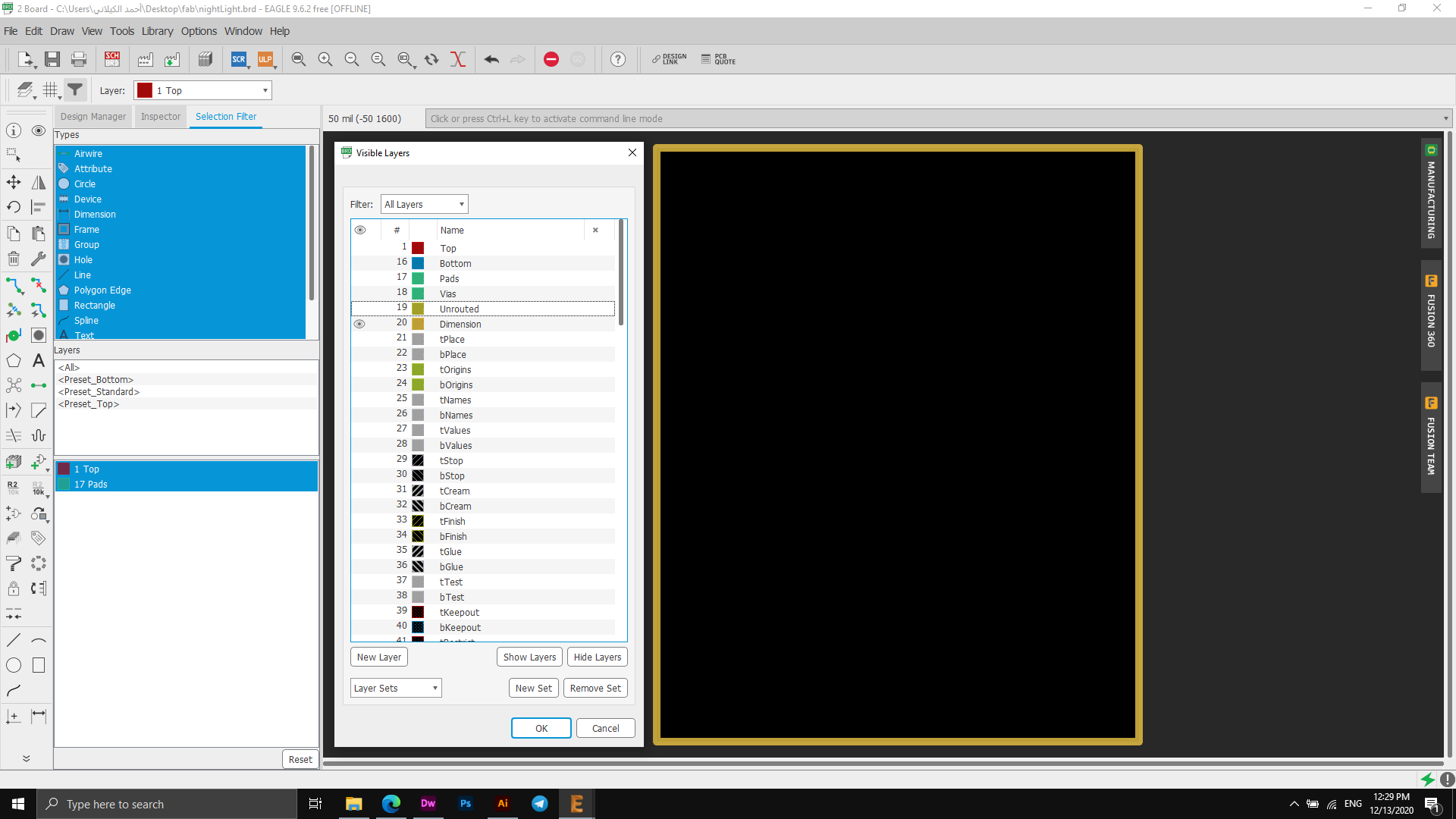
In fact, I did not encounter any problems with the connections, and I can confirm this through the image below, where the error checking process shows that there is no defect in the electronic board connection process.
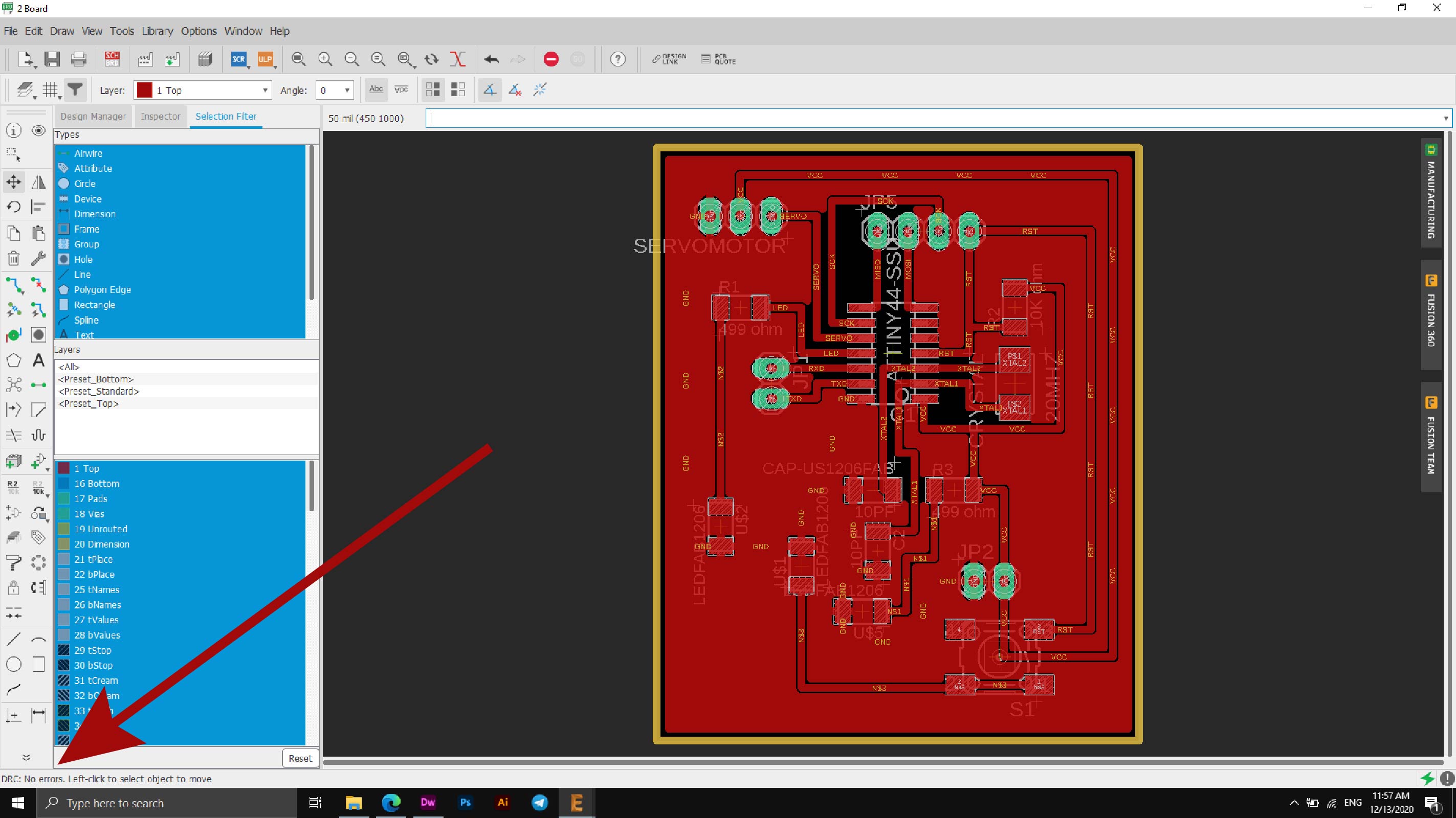
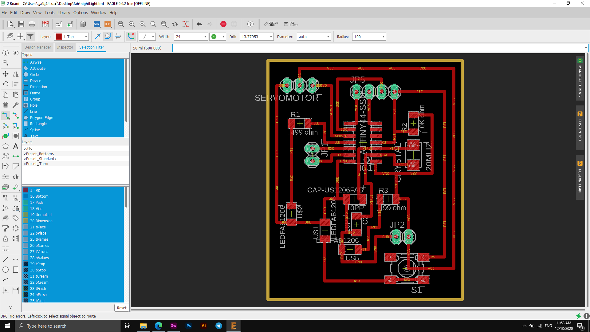
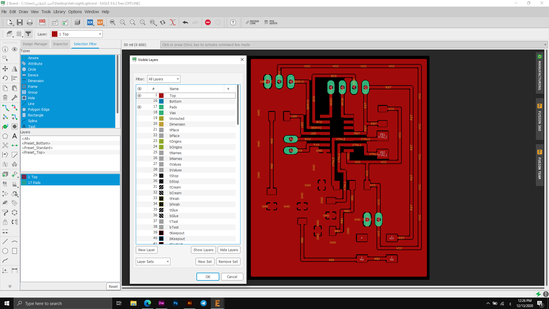
At the end I exported the circuit board I designed, you can see the export steps in the image below.
Traces Export
Outline Export
Files
PINS
Ardino Code
#include
int trig=8;
int echo=9;
int dt=10;
Servo servo;
//int distance,duration;
void setup() {
// put your setup code here, to run once:
pinMode(trig,OUTPUT);
pinMode(echo,INPUT);
Serial.begin(9600);
servo.attach(19);
}
void loop() {
// put your main code here, to run repeatedly:
if (calc_dis()<10)
{
for (int i=0;i<=540;i++)
{
servo.write(i);
delay(1);
}
delay(100);
for (int i=540;i>=0;i--)
{
servo.write(i);
delay(1);
}
delay(100);
}
}
//This code is written to calculate the DISTANCE using ULTRASONIC SENSOR
int calc_dis()
{
int duration,distance;
digitalWrite(trig,HIGH);
delay(dt);
digitalWrite(trig,LOW);
duration=pulseIn(echo,HIGH);
distance = (duration/2) / 29.1;
return distance;
}
I have given a command to the sensor to sense the movement of people, and when someone enters the range of the sensor, the sensor will stop the movement of the engine and block it.
I first raised the code on the electronic board in use, and then connected it to a 12V power supply.
At first I encountered a problem with the connections as I first tried on the Arduino board, but after switching to my electronic board, I faced a problem with the connections, but after research and experiment I solved the problem, as I had chosen wrong labels, so through this solution I was able To bypass the problem, to connect the ports to the Atmega328p, I adopted a specific mechanism as the drive port is connected to PIN 28 on the Atmega328p. This means that it is equal to the A5 port on the Arduino, and to go to the correct names, I considered that the Arduino device contains 13 named ports and then I chose PIN A0 As the number 14, the PIN A1 - 15, and on this way to the end of the A5 port, this is the correct method that I relied on.
Files - Open Source
Arduino CodeInput Device
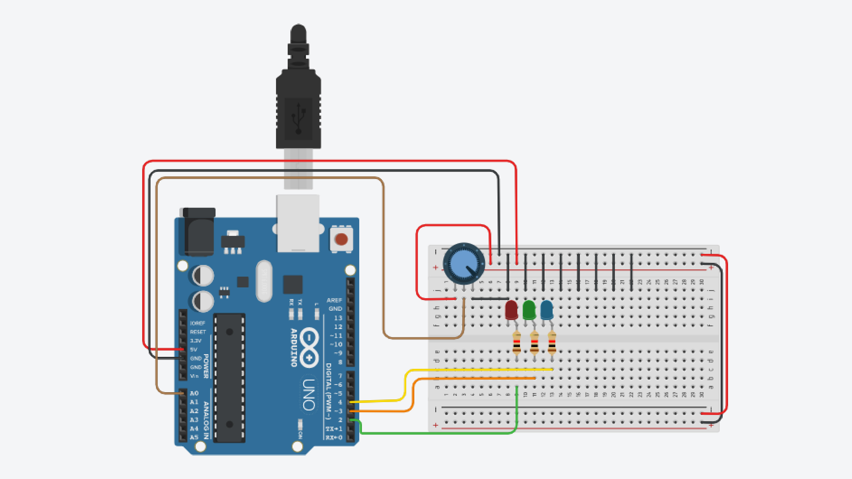
This week I did a test to test the input devices, I am supposed to use the electronic board that I designed two weeks ago but due to the conditions and quarantine on the country I live in and the laboratory closed I could not reach my Board, so I used some components as LEDs - Resistors - Ponometer - Wires - Arduino Uno - Software Arduino.
I performed the operation on three small "LED" bulbs that are controlled by the "Potentiometer" by changing the value or rotating the tool so that as we move it to the right the LEDs blink and the intensity increases, and the more we move to the left the more constant the lighting and makes it in motion sleep.
I relied on this scheme in the process of connecting pins to their correct entrances، Arduino PinOut
The following picture shows the connection process for the electronic board and what parts are used.
int led1 = 2;
int led2 = 3;
int led3 = 4;
int poten = A0;
int delayperiod = 0;
int invalue;
void setup()
{
pinMode(led1, OUTPUT);
pinMode(led2, OUTPUT);
pinMode(led3, OUTPUT);
pinMode ( poten, INPUT);
}
void loop()
{
invalue = analogRead(poten);
delayperiod = map(invalue,0,1023,0,100);
digitalWrite(led1, HIGH);
delay(delayperiod); // Wait for 1000 millisecond(s)
digitalWrite(led2, HIGH);
delay(delayperiod); // Wait for 1000 millisecond(s)
digitalWrite(led3, HIGH);
digitalWrite(led1, LOW);
delay(delayperiod); // Wait for 1000 millisecond(s)
digitalWrite(led2, LOW);
delay(delayperiod); // Wait for 1000 millisecond(s)
digitalWrite(led3, LOW);
delay(delayperiod); // Wait for 1000 millisecond(s)
}
The text above represents the programming code that controls the entire lighting process, as it is through this code that the lamps can be programmed and made to light as required.
part One:"int ledx" This code represents the LED number, through which I can give a specific number or a name according to the connection in the board, if I have an LED connected with the input number 10, I must write the code in the following form "; int led10 = 10" and if I want to put a label For him, I can write the code as follows "int led10 = example". When naming, you must change the LED number in all other codes and convert it to the name you have set. This process will facilitate the knowledge of errors if they occur.
This code indicates "int poten = A0;" Until the Potentiometer device is connected to the Analog A0 port, which is where we can control the lighting intensity and downgrade, and at any value, the changes are made between modes, for example fast lighting, slow operating, stability and more.
Part tow setup function, the initialization function is where the port is initialized. It is executed only once when the arduino code is run for the first time.
PinMode (Led, OUTPUT) function has two variables inside it, the first indicates the port number.
INPUT: In the event that the other device sends an order or signal to the Arduino (such as a push button).
OUTPUT: When an order or signal is sent from the Arduino to other devices such as (the little bulb).
Part three: Loop is the main function in arduino and iterative.
If the example is modified to one minute: "1000*60" = 60000 milliseconds refer to one minute
The following video shows the process in full form and how to fully control the lighting and lighting pattern.