Networking And Communications
This week, I connected 2 Arduino Uno through my computer and created a connection between them to operate the light through another Arduino device, I used 2 Arduino in addition to an LED and Potentiometer, I control the lighting speed and turn on the light through the control In the Potentiometer level, I showed the values that the Potentiometer is transmitted to through the Serial Monitor.
This can be done through the Tools tab and choosing the PORT input. More than 2 Arduino can be placed according to the USB ports of the computer, but this will require more energy and when the computer is not able to give the required power, damage to the computer or burning may occur, so it is necessary to be careful while dealing With these experiences.
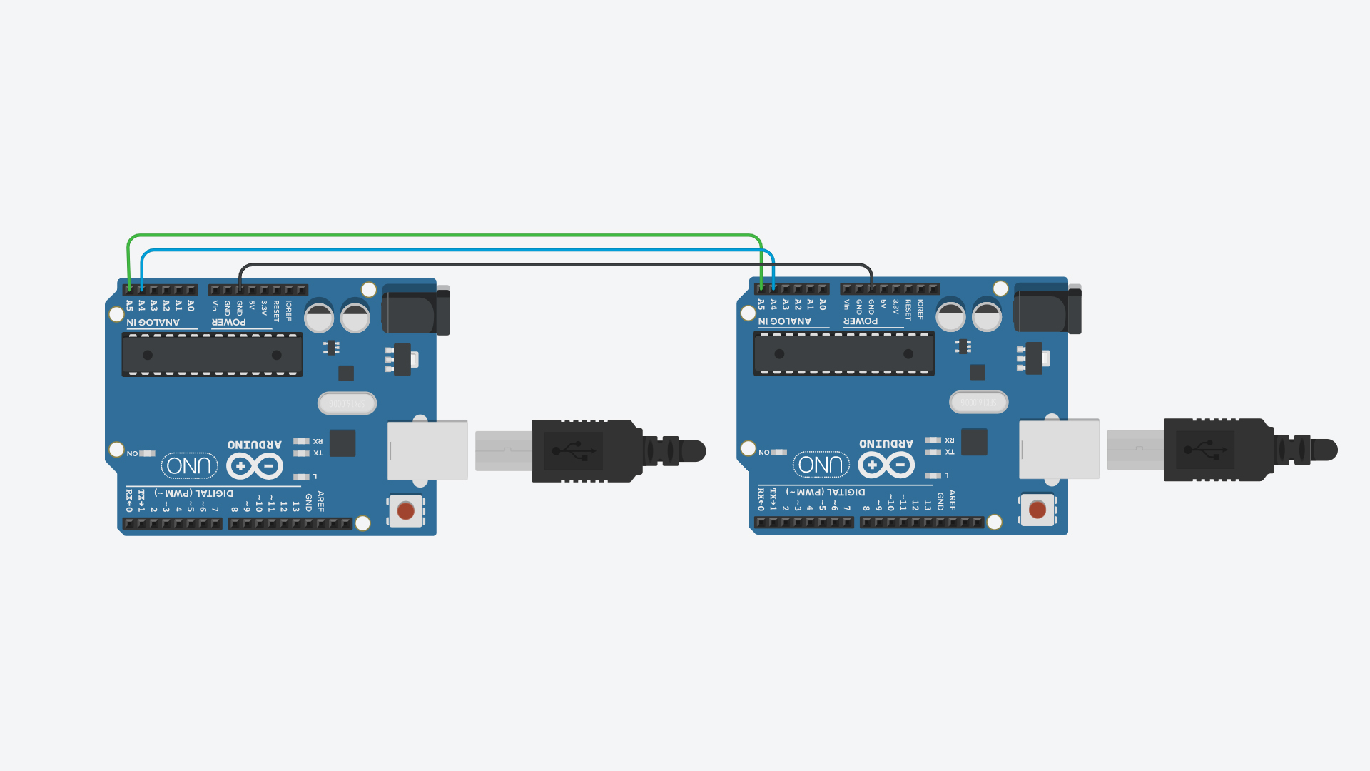
The 12C protocol involves using two lines to send and receive data: a serial clock pin (SCL) that the Arduino Master board pulses at a regular interval, and a serial data pin (SDA) over which data is sent between the two devices. As the clock line changes from low to high (known as the rising edge of the clock pulse), a single bit of information - that will form in sequence the address of a specific device and a a command or data - is transferred from the board to the 12C device over the SDA line. When this information is sent - bit after bit -, the called upon device executes the request and transmits it's data back - if required - to the board over the same line using the clock signal still generated by the Master on SCL as timing.
Connect pin A4 (the data, or SDA, pin) and pin A5 (the clock, or SCL, pin) on the master board to their counterparts on the slave board. Make sure that both boards share a common ground. In order to enable serial communication, the master board must be connected to your computer via USB.
If powering the boards independently is an issue, you can power the Slave from the Master board. With a 5 V Slave, this would be done by connecting the 5V output of the Master to the 5V pin on the slave.
After I connected the two boards as mentioned above and created a communication basket between them through the connections I completed the process and completed the connection of the experiment that I will be working on, I connected the LED and the Potentiometer with my two Arduino devices, each of them connected to a separate board, but in reality it is connected through the computer which It will act as a means of communication between them, the LED lighting speed is judged by a Potentiometer, I used a Serial Monitor to control the lighting speed or not.
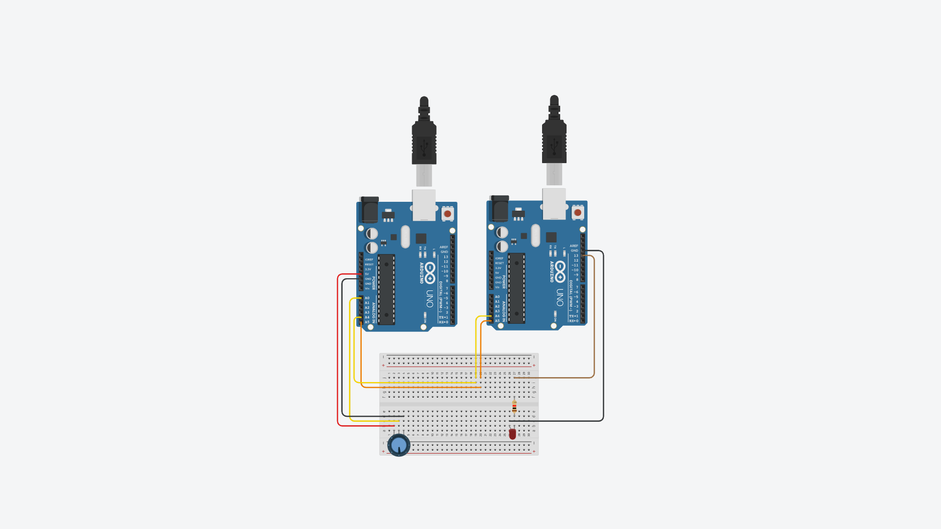
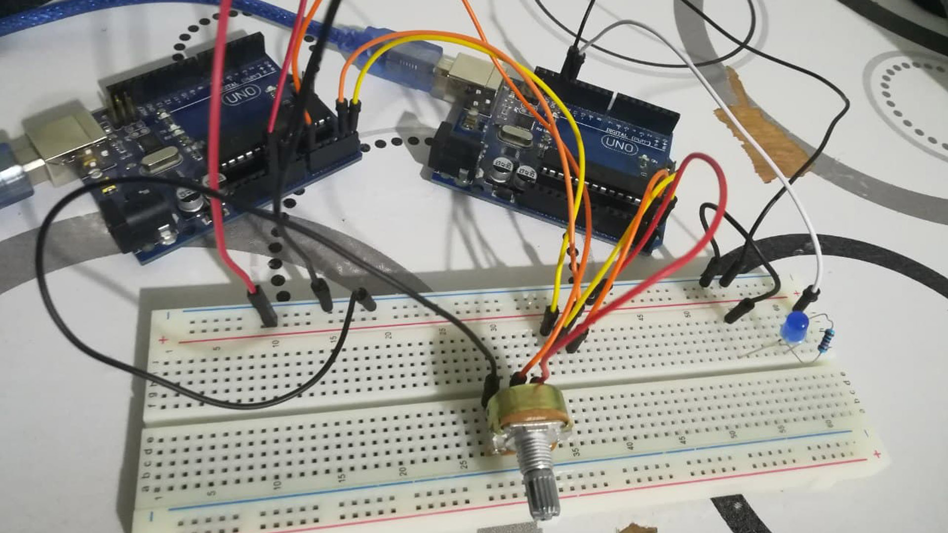
I connected the two panels by making a connection between them via Breadboard, which is the best way to avoid using Breadboar, but I preferred that due to my lack of long Jumbers.
I have written and prepared the codes for both devices, where I have prepared the Master Code, which will be the main device or controller that will control the process through the Potentiometer, and the other device Slave as it will act as a controller with it.
The following video explains the experience that I did by connecting two Arduino devices and how to control them and make a connection through them. I downloaded the code on both boards.
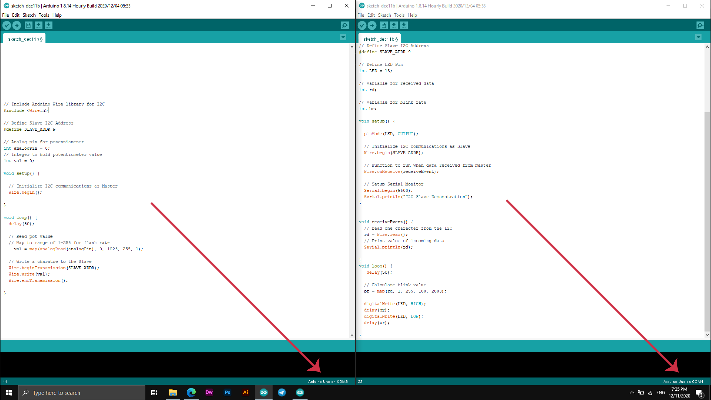
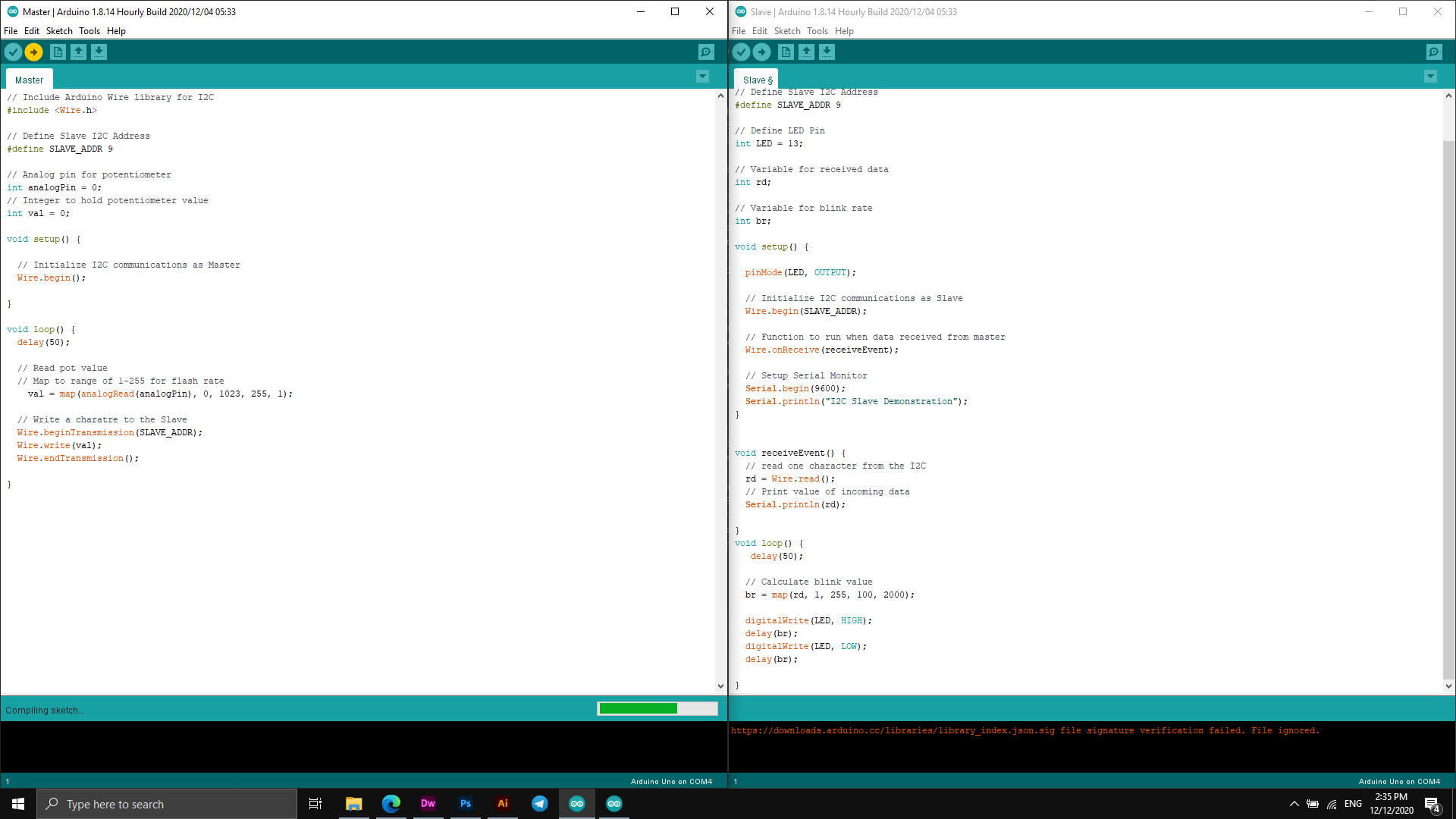
Codes
Master Code
Slave Code
This week I did an experiment and simulation through the process of connecting the Bluetooth piece to the computer and sending information to the computer through the Android application installed on my device!!
Connection and networking process:
In telecommunications, a communications protocol is a system of rules for exchanging data within or between computers.
Protocol constitutes the charter, standard, or agreement that organizes and enables the process of connection, communication, and data transfer between two devices. In the simplest form, we can define a pact as the “rules of governance”, syntax, semantics and synchronization in the communication process. The protocols can be implemented by hardware, software, or a combination of this and that. Compact at its lowest level defines the communication behavior of hard hardware. To reach an agreement, a protocol can be developed in a technical standard. A programming language describes itself with mathematical proportion, so there are close similarities between the protocols and programming algorithms.
I was supposed to do this experiment on the electronic board that I designed at Electronics Design Week but as a result of the ban in the divided country and the Corona pandemic I had to do the job on some of the pieces I have.
How Bluetooth works in the Arduino
HC 05/06 works on serial communication. The Android app is designed to send serial data to the Arduino Bluetooth module when a button is pressed on the app. The Arduino Bluetooth module at the other end receives the data and sends it to the Arduino through the TX pin of the Bluetooth module (connected to RX pin of Arduino). The code uploaded to the Arduino checks the received data and compares it. If the received data is 1, the LED turns ON. The LED turns OFF when the received data is 0. You can open the serial monitor and watch the received data while connecting.
In the beginning I prepared the parts and what I used was:
The first step I took was to connect the bluetooth piece to the Arduino as I connected it based on the code that I have suppressed for this process.
The following picture shows the places of delivery and the parts used.
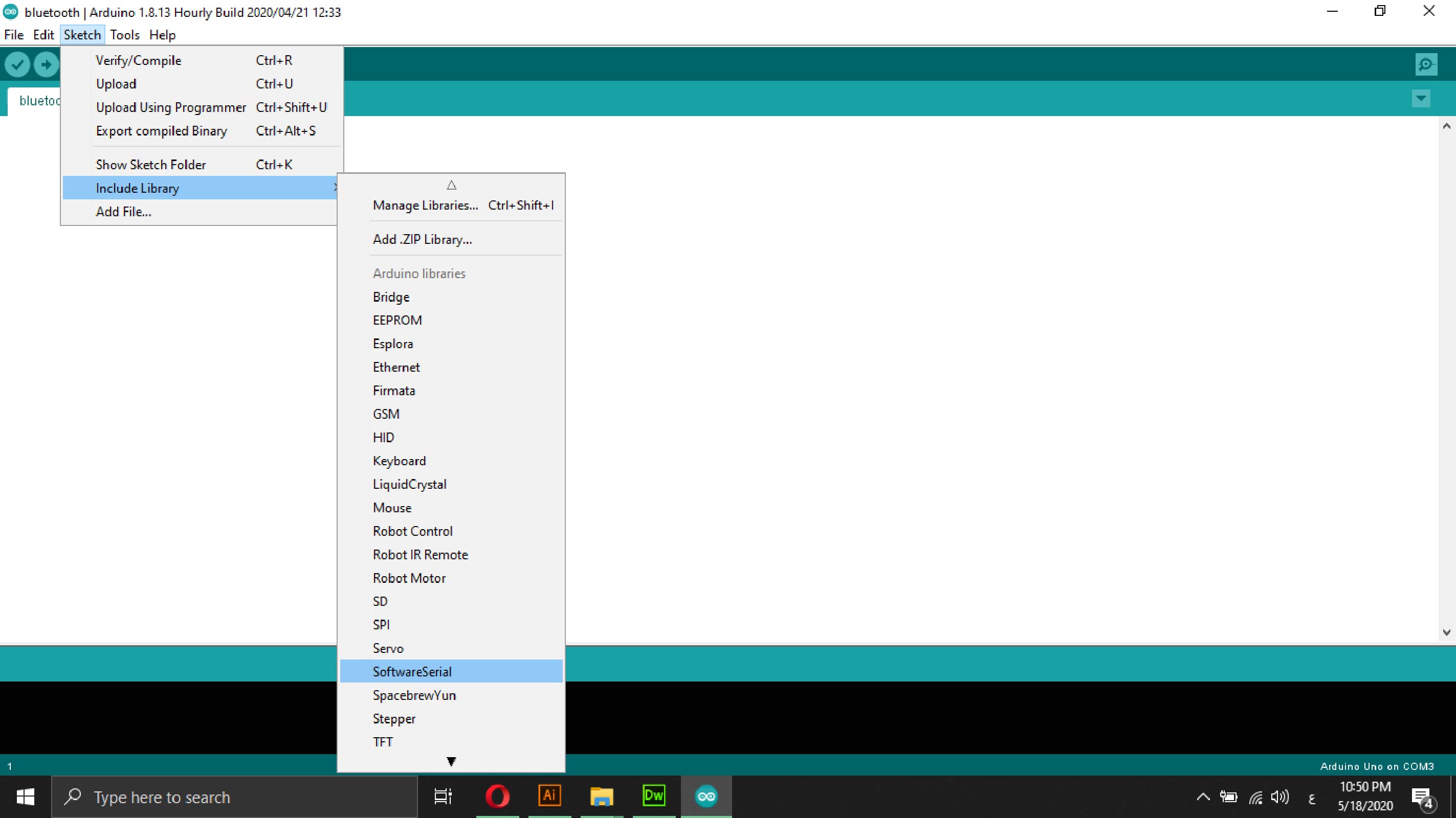
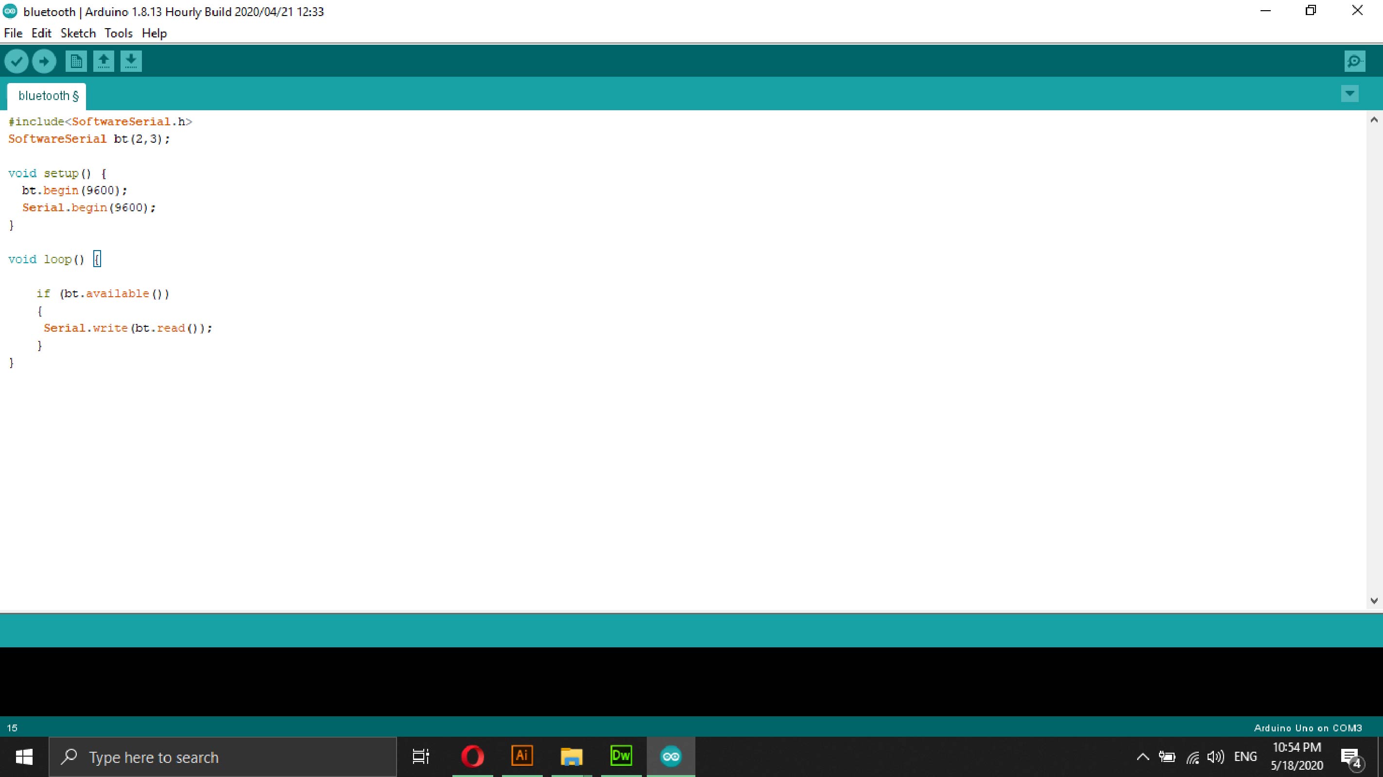
The image below shows the code you used in the process of sending data through a mobile phone to a computer.
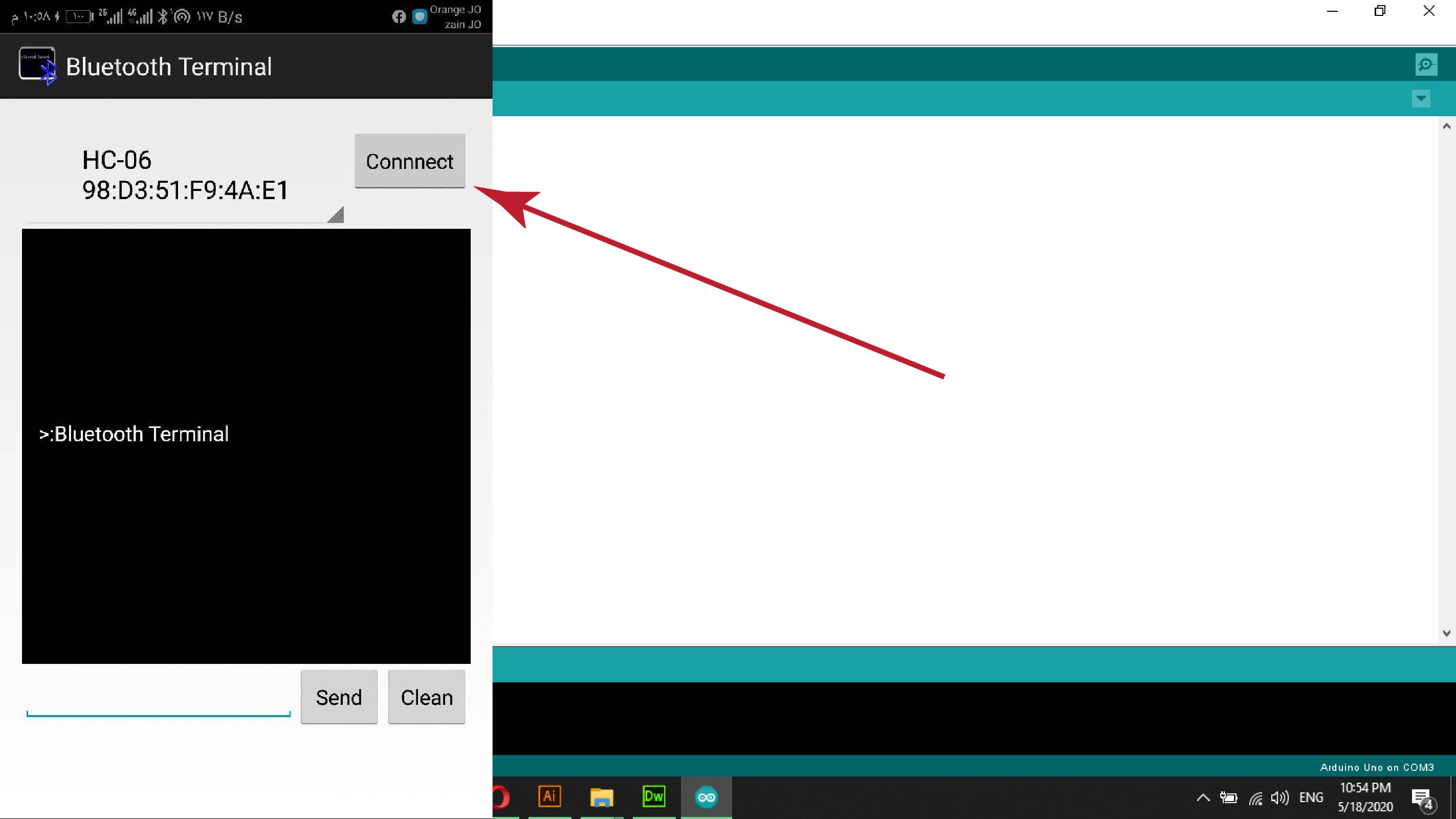
The second step I downloaded the Blutetooth Terminal app from the Google Play app store, when opening the application he asked to open the bluetooth to connect to the bluetooth piece used in the process to be able to make pairing.
After opening the bluetooth, the widget that I want to establish the connection between it and the bluetooth appeared, then I pressed a connection to establish the pairing immediately.
After preparing the connection, I opened the "Serial Monitor" interface and started to send information and texts through the Bluetooth Terminal program on the Android device, and the texts and data sent directly will appear on the computer screen, in the next video, an explanation of the process you have performed.
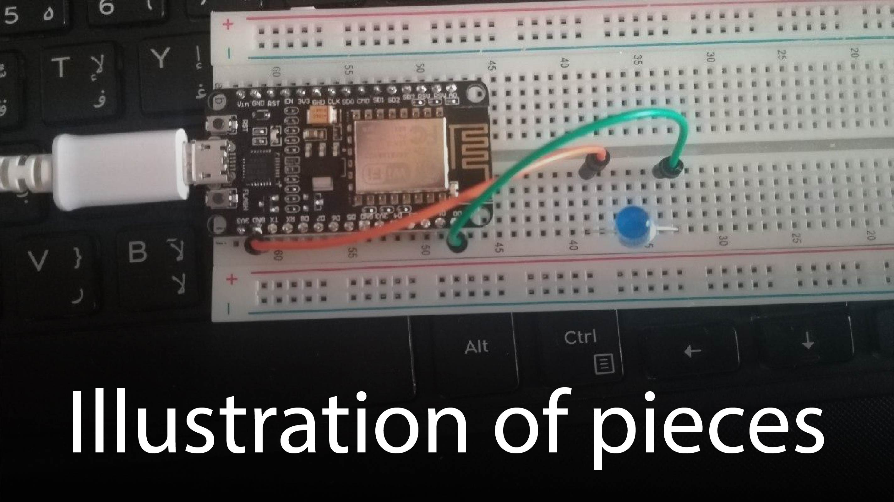
LED Operation Experience by Node MCU
How Wifi works with Arduino
The Arduino Uno WiFi is an Arduino Uno with an integrated WiFi module. The board is based on the ATmega328P with an ESP8266WiFi Module integrated. The ESP8266WiFi Module is a self contained SoC with integrated TCP/IP protocol stack that can give access to your WiFi network (or the device can act as an access point). One useful feature of Uno WiFi is support for OTA (over-the-air) programming, either for transfer of Arduino sketches or WiFi firmware.
Initially I prepared the parts and what I needed:
My first step was to start connecting the parts together so that I could establish a connection between them.
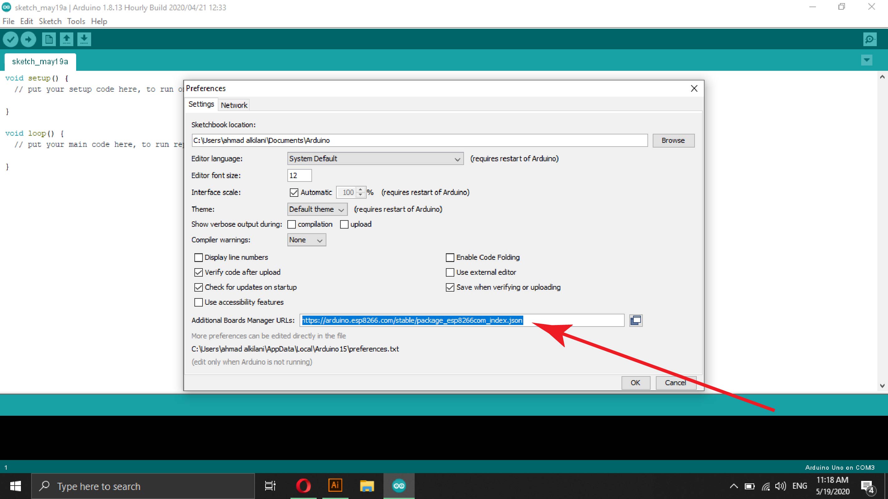
After connecting the parts, I moved to the computer and opened the Arduino software and then installed one of the packages "esp8266" so that the program can identify the piece and its use through the program, to install the package, I went to the "File - Prefrences" tab after opening the window, I paste the package link in the rectangle Shown in the image below and then equip the library through the approval button.
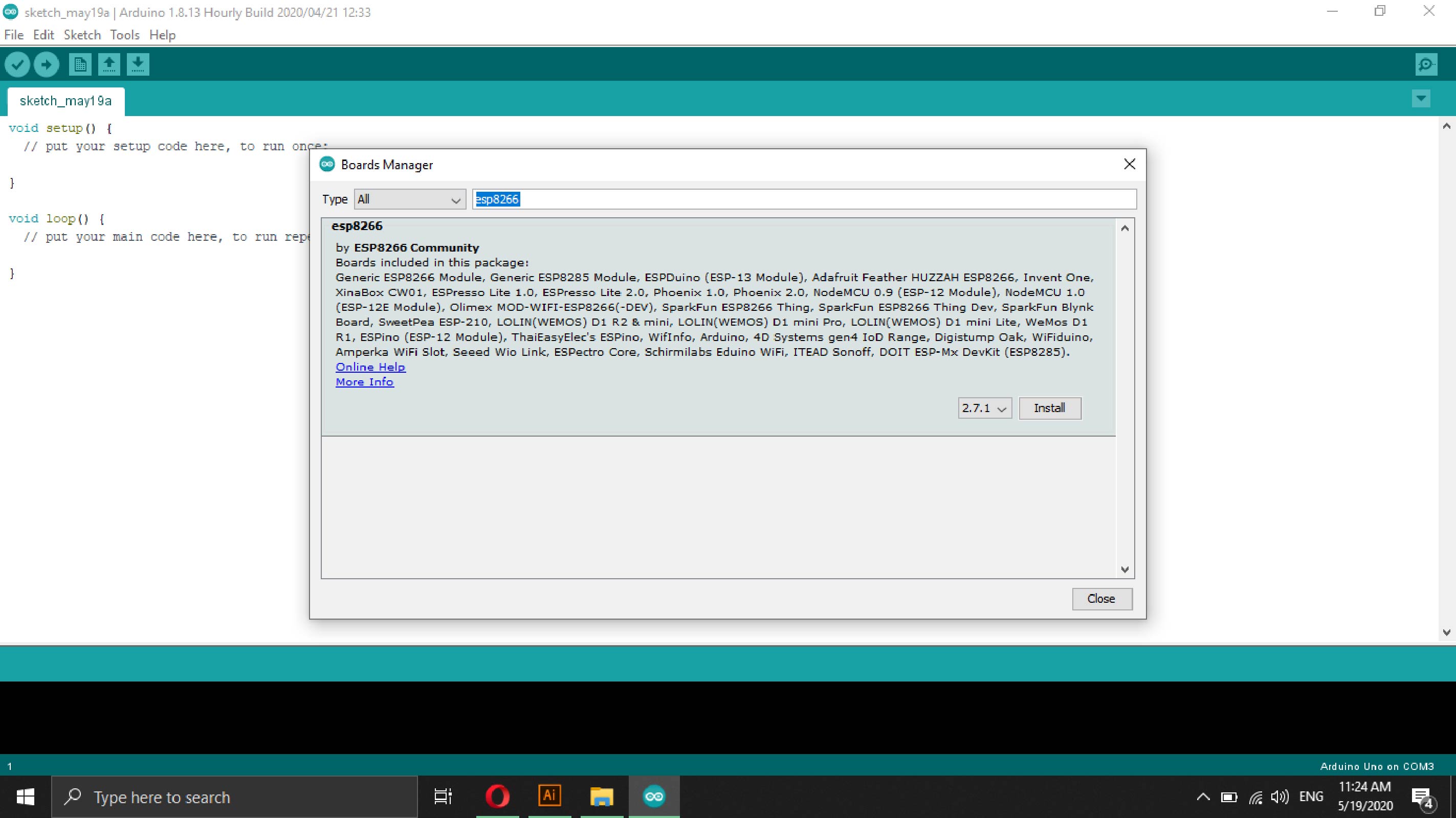
The second step is to install the library so that I can go to the next track "Tools - Board -Board Manager" through the search box in the window that appeared, I searched for "esp8266" which is the same name and number of the piece that I am working on and as I mentioned earlier that this package is intended to bring Code and identify the piece and deal with it, after finding the package I installed it as shown in the picture below.
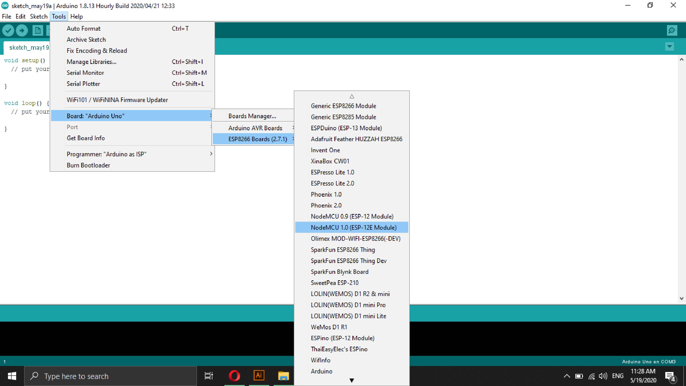
To prepare the code, I also went to the "Tools - Board - ESP8266 - NodeMCU 1.0 (ESP-12E Module)" tab. From the Port tab, I selected the option I needed "COM4".
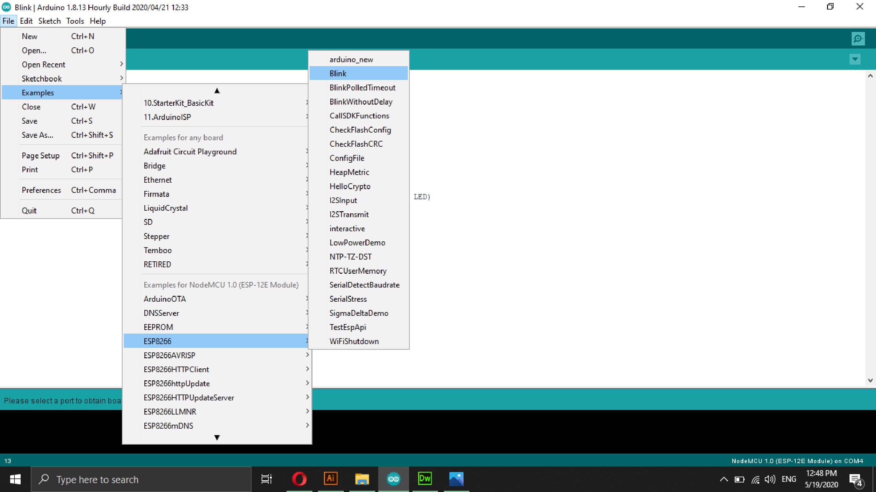
To get the code I went to the installed package and choose the process that I want to try it on.
The following picture shows the connection process for parts.
Watch the video to find out more:
Files - Open Source