Electronics Prudctions
During this lecture, we learned the basics of designing electronic boards through several steps. This process is to design the electronic board through a program designed for panels such as "Eagle". In the second step, the process of cutting and digging the plate through the "PCB" cutting machines.
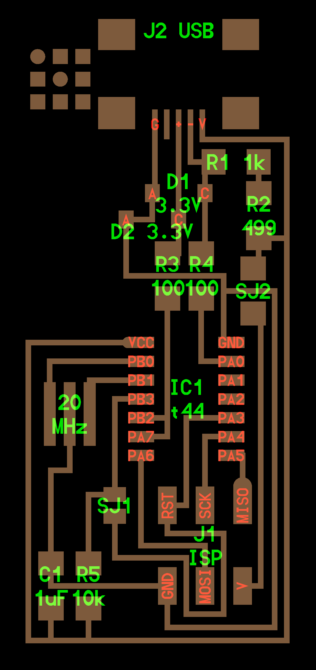
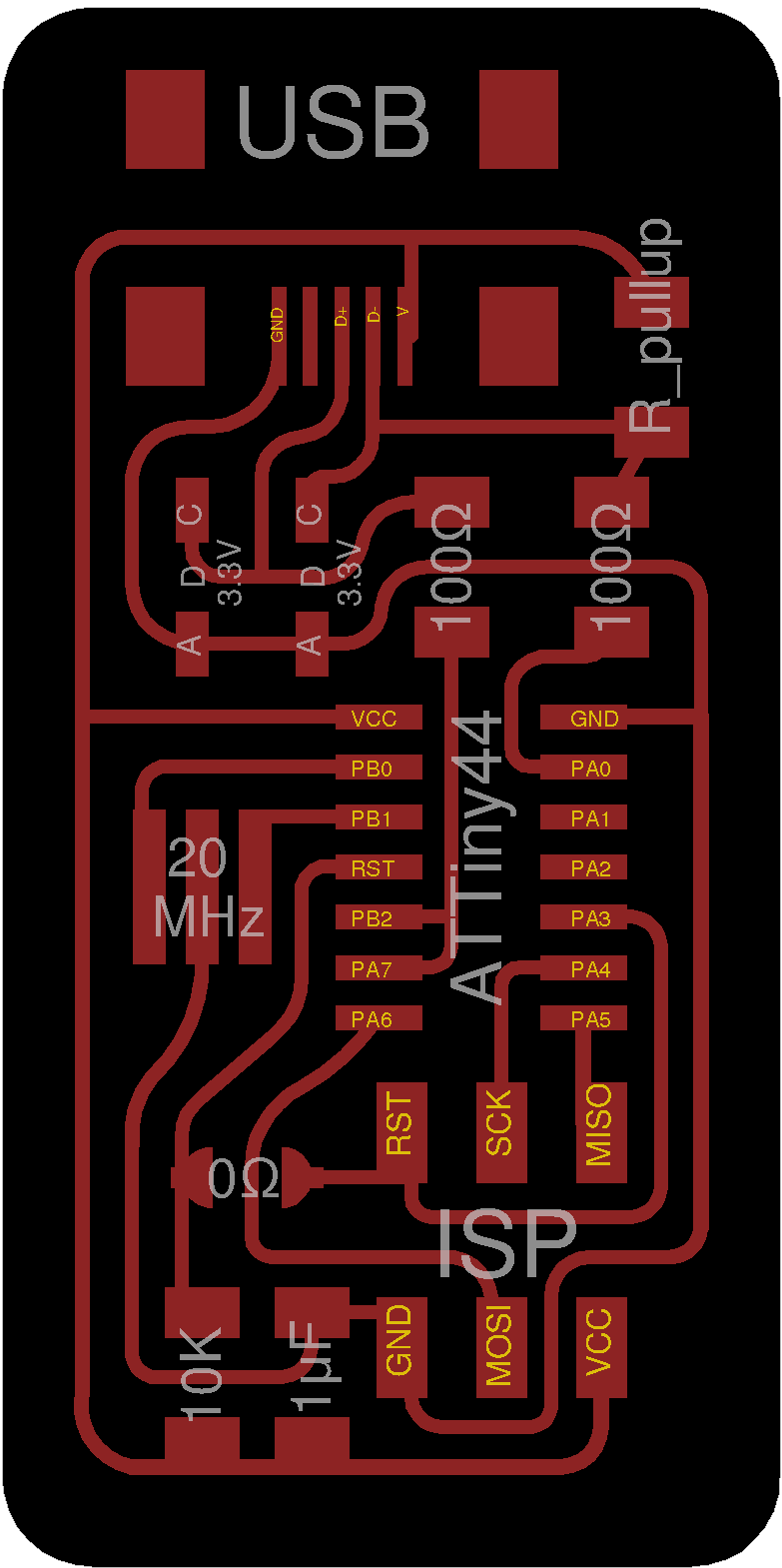
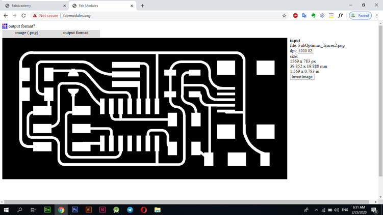
I have prepared the attached design on the website FabAcademy, designed by Ali, the design was uploaded at the time of uploading it on the site FabModules.
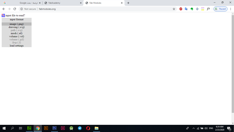
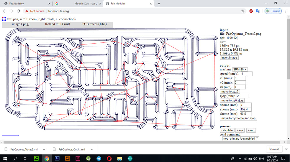
Through the "input format" option, I chose "image.png" and selected the image to work with.
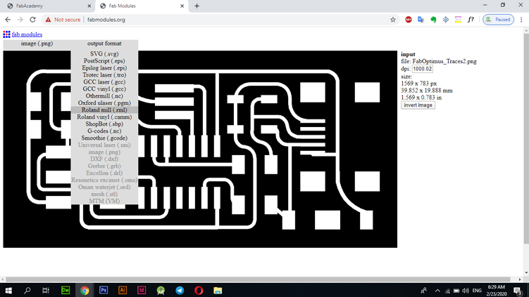
After selecting the image and opening the "OutPutFormat" option, I chose the type of machine that will be worked on, and according to the available option, I choose "Roland Mill".
I chose "PCB Traces 1/64" because the work is in the interior, also the "End Mill" must be placed with the specifications that were chosen for it and during the process of adjusting the settings.
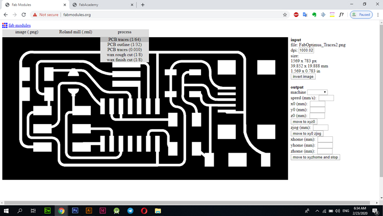
In the sidebar we need to adjust some settings like "Speed - Machine Type - Drill Level".
The next image and in the red box show the values and types chosen
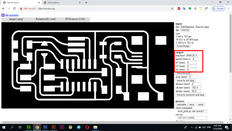
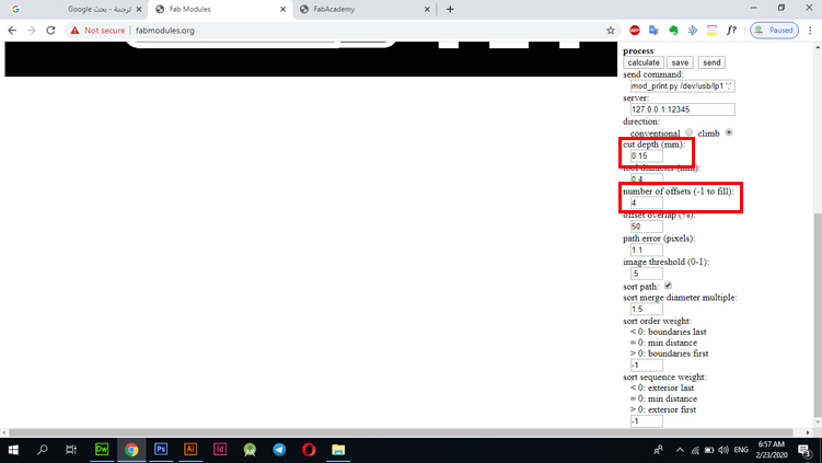
Also here are some set values:
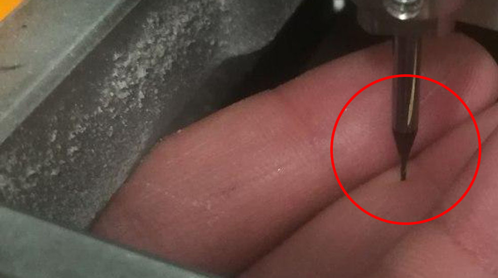
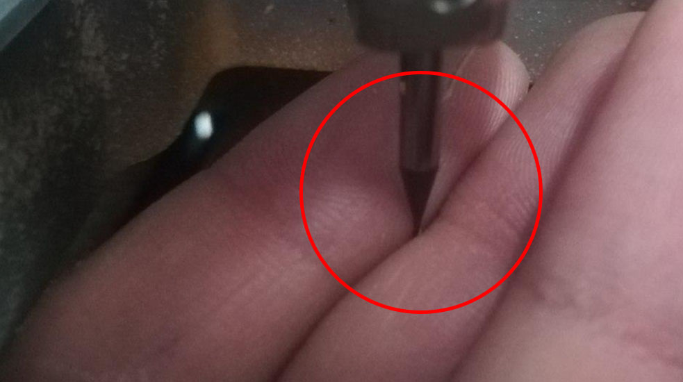
This is the right "End Mill" for the Traces cutting board.
Now you should save the file by pressing the save button in the interface whose settings are adjusted in the attached image above.
The site will save the file in the form "example.rml". All you need to do is save the file and go to the program designated for controlling the "RolandMill" and the beeping of the indicator "X - Y - Z". The electron that will be shear on me, you can find this out by examining it with a voltmeter device where you put my two voltmeter heads "head on the surface of the electronic board and the second head on the "End Mill" head that has been installed", there are several types of vane that will be used. 1/64 "while in the frame trimming process a 1/32 type brush is used.
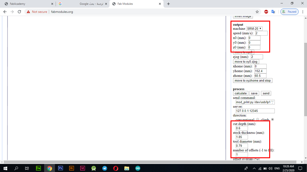
As shown in the image below, we have used the type of "PCB outline 1/32" which is the type designated for cutting frames in the "OutLine" boards.

I also used and adjusted some settings in the first stage of “Traces” cropping. I also adjusted the settings to suit the final cutting of the OutLine. You can go down below to see the changing settings.
These are files created by the FabModules website and ready to be cut directly as all required settings are included.
This is the code used for the "OutLine" stage.
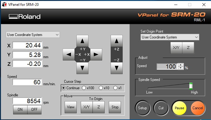
In the following image, the interface of the machine handling program indicates that I have zeroed the cursor so that the shear is in the right place and the plate is dug with the appropriate depth for it.
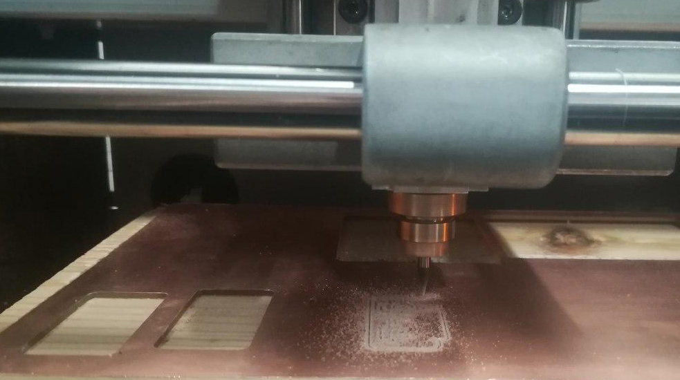
Cut the board
This is the PCB Roland SRM20 circuit board shearing process.
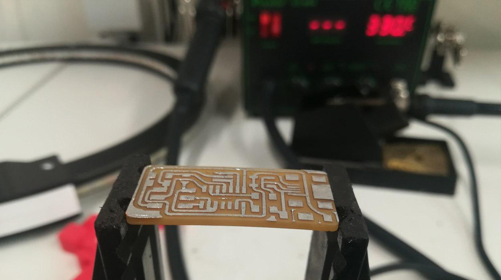
I had to put the tin on the circuit board tracks to facilitate the cutting process of the electronic plate cutting, so I prepared the plate and added the tin to all its parts to ensure the easy installation of the pieces after this process.
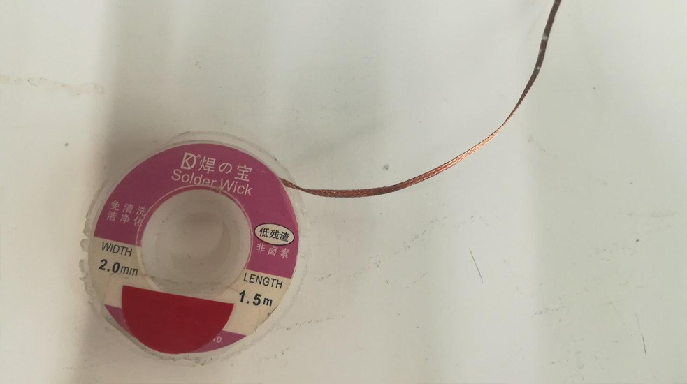
I have faced one of the common problems which are the black pieces that appear on both ends of the lines which prevent the tin from sticking to the electronic board well, so I used a "Solder" wire and passed it with the caustic to the dirty places.
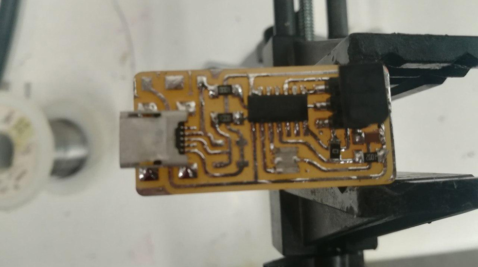
After solving the problems in the last step, I started installing the pieces and produced this shape. I used caustics, tin pieces, and tongs to be able to control the location of the piece.
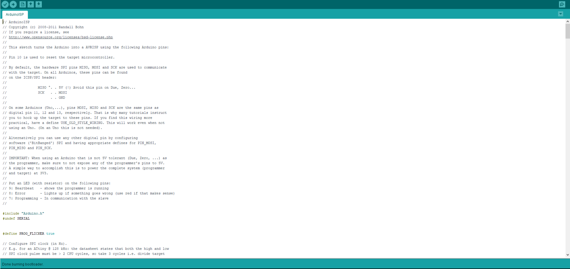
These electronic boards are programmed through the Arduino program and run by the Ubuntu system. In the Urdu program, all you need to do is choose your board information and when this process is finished, I give the download command through the taskbar at the top "BootLoader".
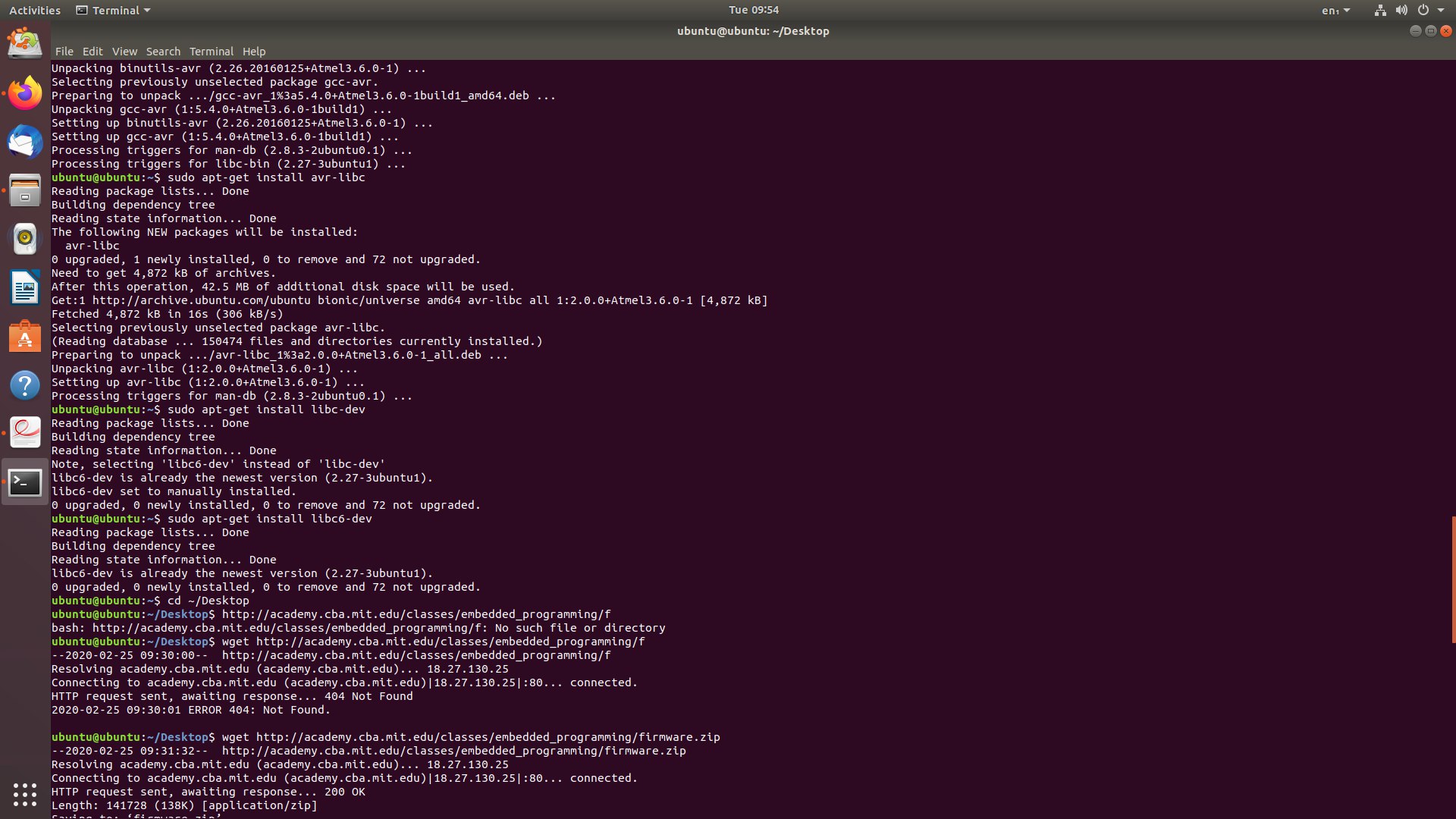
In this step, the Ubuntu system must be installed to program the electronic tablet on it through several commands that are applied through the default program added in the system by default, "Terminal". After installing and opening the Ubuntu system, we open the "Terminal" program through the application panel in the bottom, or use the option to search for the program.
Use these commands to access the desired file and to perform the whiteboard programming process
The following commands are to download the firmware. Firmwares are kinda like the DNA of the board, it's something permenant and is burnt on a read-only memory. I downloaded it on the desktop and unzipped it.
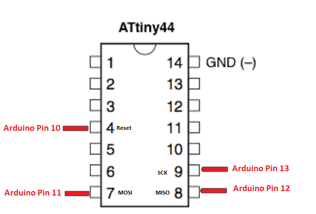
Program an Arduino as an ISP & Connect your board to the Arduino ISP as seen
After that, I connected the arduino and my milled board to my computer and then opened the terminal. To understand the next commands, you need understand what a makefile is. A makefile is a bunch of rules that explains how your board reacts based on certain prerequisites which affects the outcome of the program, called "target". In the end you'll have an executable file that dictates how your board operates.
Edit the makefile (A makefile is a bunch of rules that explains how your board reacts based on certain prerequisites which affects the outcome of the program, called "target". In the end you'll have an executable file that dictates how your board operates).
Comment this line AVRDUDE = avrdude -c avrisp2 -P usb -p $(DEVICE) by adding a hashtag "#" and instead I typed AVRDUDE = avrdude -c stk500v1 -P /dev/ttyACM0 -b19200 -p $(DEVICE)
An illustration of the process: