-
Fab Academy 2020
-
Design. Make. create.
-
Shape the Future
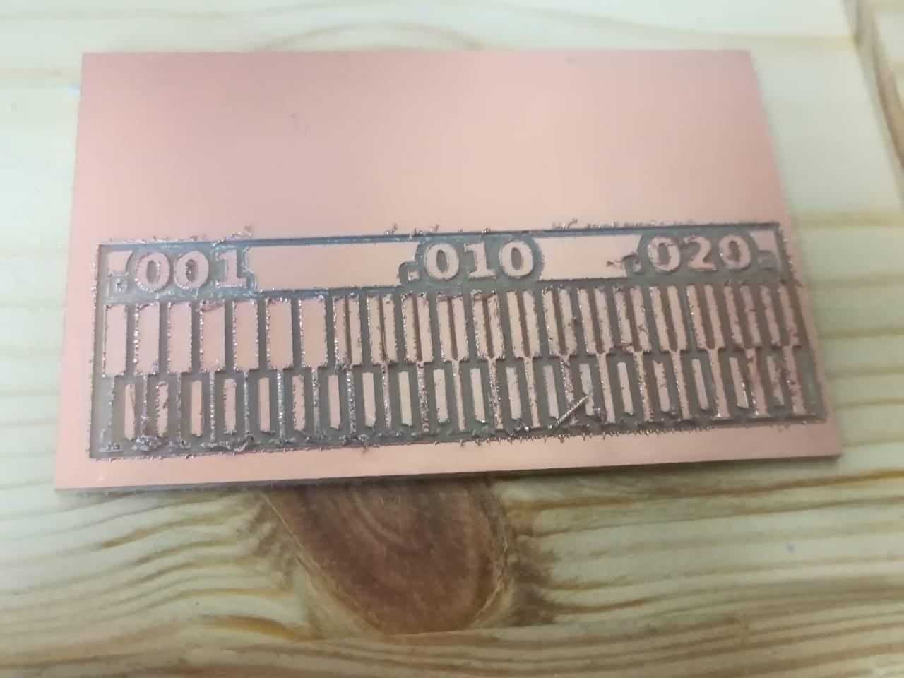
This week we performed a "characterize the design rules for your PCB production process" As required in "Electronics Production Week".
Initially we needed a CNC machine to work on the above design and we used the machine available in the laboratory "PCB Machine - SRM 20"
After preparing the design in "PNG" format, we prepared the machine to start the cutting process, starting with the "Fab Modules" website, through which we can set the settings for the electronic board cutting.
| Mission | Size Or Type |
|---|---|
| dpi | 1500 |
| machine | SRM-20 |
| speed (mm/s) | 1 |
| x0 (mm) | 0 |
| y0 (mm) | 0 |
| z0 (mm) | 0 |
| cut depth (mm) | 0.1 |
| tool diameter (mm) | 0.4 |
| number of offsets (-1 to fill) | 4 |
| Mission | Size Or Type |
|---|---|
| dpi | 1500 |
| machine | SRM-20 |
| speed (mm/s) | 1 |
| x0 (mm) | 0 |
| y0 (mm) | 0 |
| z0 (mm) | 0 |
| cut depth (mm) | 0.6 |
| stock thickness (mm) | 1.7 |
| tool diameter (mm) | 0.79 |
| number of offsets (-1 to fill) | 2 |


The site will save the file in the form "example.rml". All you need to do is save the file and go to the program designated for controlling the "RolandMill" and the beeping of the indicator "X - Y - Z". The electron that will be shear on me, you can find this out by examining it with a voltmeter device where you put my two voltmeter heads "head on the surface of the electronic board and the second head on the "End Mill" head that has been installed", there are several types of vane that will be used. 1/64 "while in the frame trimming process a 1/32 type brush is used. As shown in the image below, we have used the type of "PCB outline 1/32" which is the type designated for cutting frames in the "OutLine" boards.


1/64

1/32

RolandMill Settings

After that, the cutting process is done through the cut button in the above image, then selecting the required file and making sure to choose the appropriate feather.