Embedded Programming
What is Embedded Programming
Embedded systems are systems for processing information and are embedded in a larger product and they are usually not directly visible to the user, and the primary goal of purchasing the product is not the embedded systems themselves, but the product that contains those systems and the functions that they perform, and the embedded systems are Post-personal computer processors, as data processing is no longer limited to computers with general functions, but rather has become an essential part of a wide range of devices so that these systems have become specialized to perform a specific function. Examples of embedded systems include information processing systems in wired communication devices And wireless, transmission systems and equipment in the manufacture of consumer electronics.
Embedded systems are designed for specific purposes, such as controlling, communicating, or communicating with the user through a conversational interface, and they often function in real time, and they are often part of a larger system (they may include mechanical components and the hardware)
In which the solid entity HW meets with the SW programmatic hardware in one environment to achieve the required integration, where the programmatic hardware leads the solid hardware in order to implement the task or tasks required of it. In short, they are (computer equipment for special purposes or limited to high accuracy), unlike computers that are general purpose computers. Also known as embedded systems or buried systems.
All embedded systems contain a core or cores that carry out the processing process, they may be microcontrollers or digital signal processors and it is the most important part of the physical components of embedded systems.
Embedded systems are systems specially designed to do a specific task or tasks, so it is possible for designers to optimize compact systems by making them as small as possible, not consuming much power, and doing their job with high reliability.
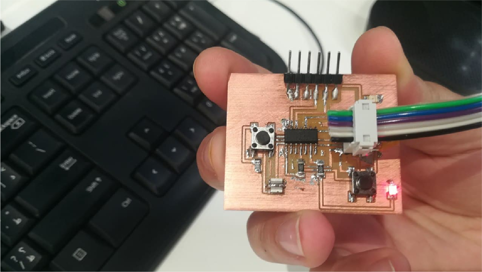
This week's job is to read console data that has been added to my Board, which I have peaked over the past weeks.
Programming
Initially, I programmed the electronic board that I designed at Electronics Productions Week, as a programmer for the new electronic board, through the Arduino IDE.
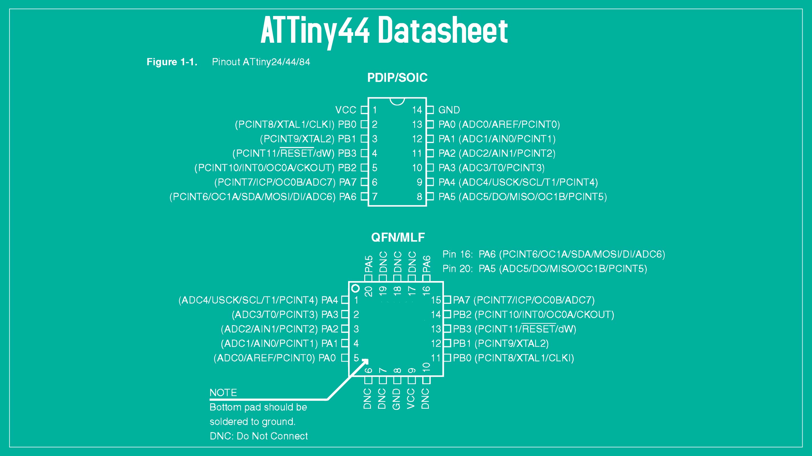
Before starting the programming process, I had to read the datasheet to understand the programming mechanism and use PINs in the correct way. By reading the data sheet, I found that there are three different types of ports, there are DDR for the Data Direction Register, PIN for the Pin Input Register, and PORT for Pin Output Register. Also, every port works differently، This week assignment was to program the board we worked on in 2 weeks ago using low level programming. To do that we have to read the datasheet for the microcontroller we used which is ,Attiny44.
FabISP With Arduino
During Electronics Production Week, I manufactured the FabISP circuit board and programmed it through the Arduino to do programmer tasks in the coming weeks.
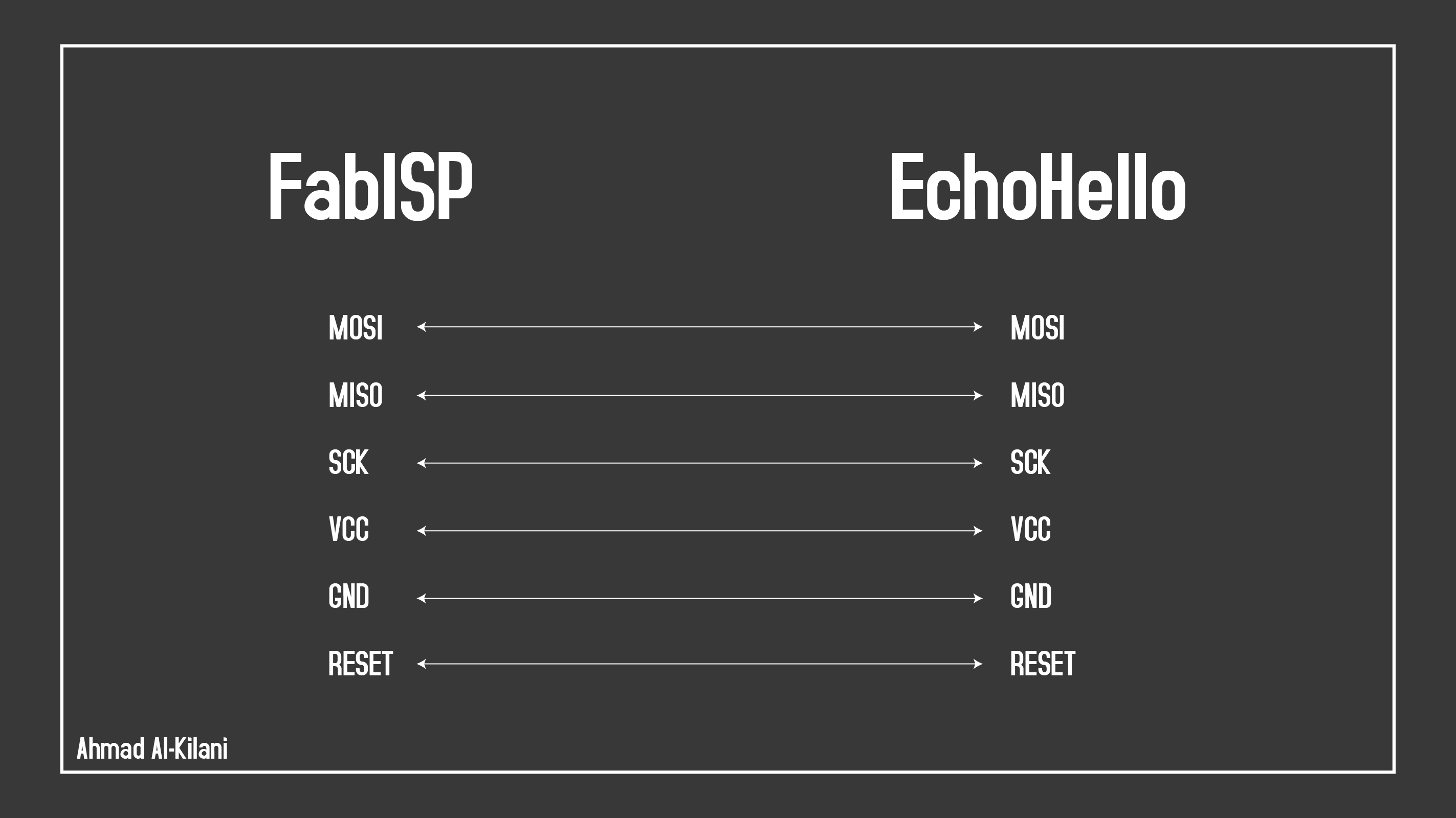
To connect the two panels to each other, follow the connections in the image below.
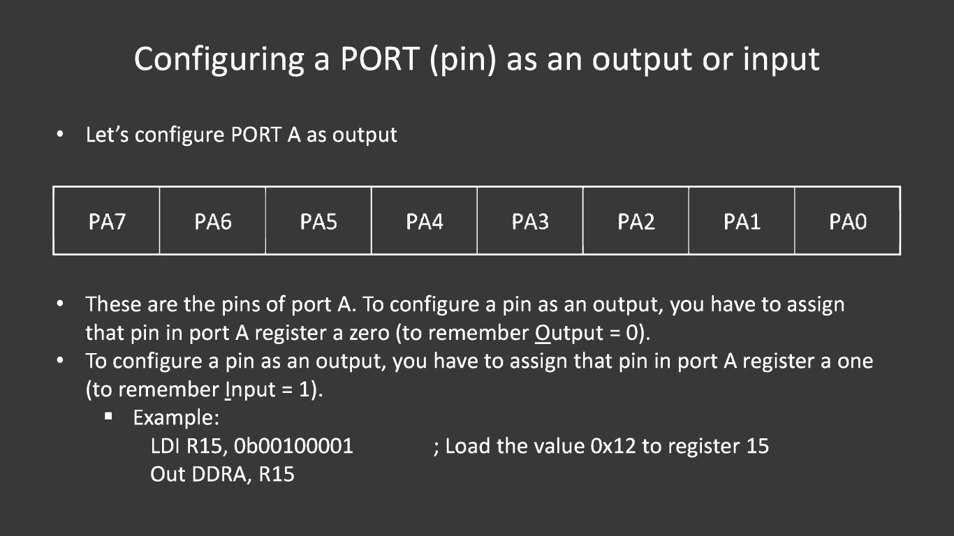
It is important to know that the Attiny44 has 2 ports, each port has 8 pins which means that we have 16 GPIO
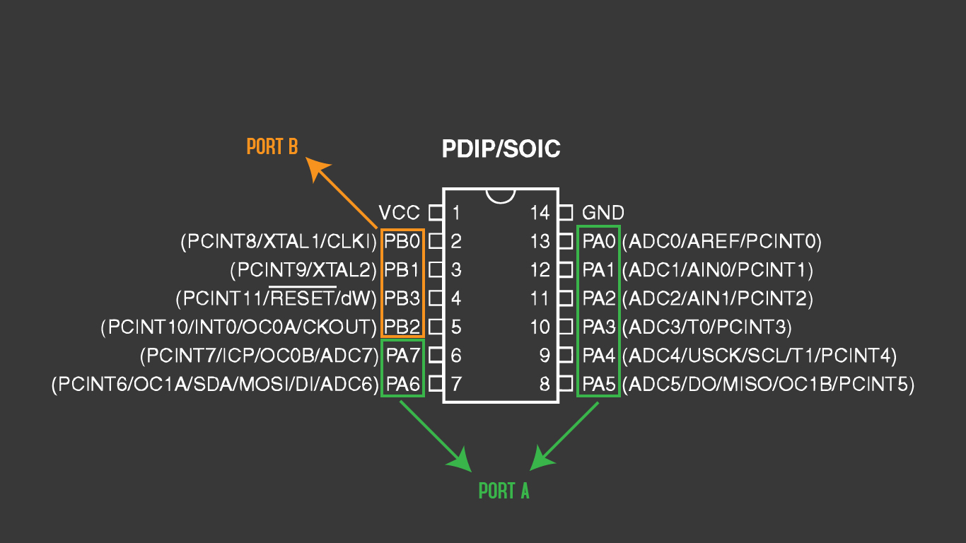
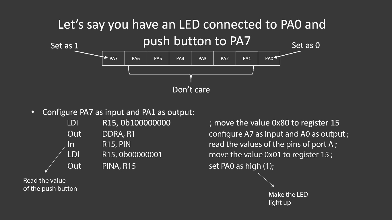
To configure a pin as input or output you have to configure it in the DDRX register, where x is the port. For example, if you want to configure pin 2,5 and 7 in PORTA as input, and the rest as output you have to give it the following: DDRA= 0b 01011011, where 0 means the pin is configured as input and 1 means the pin is configured as output.
The following image shows the connection mechanism and Pin selection in the code.
I have read some information about embedded programming to be able to do my electronic board programming, I have used the Fab Academy website to get some information on how to create a Makefile and learn about the embedded programming week more broadly.
C Language
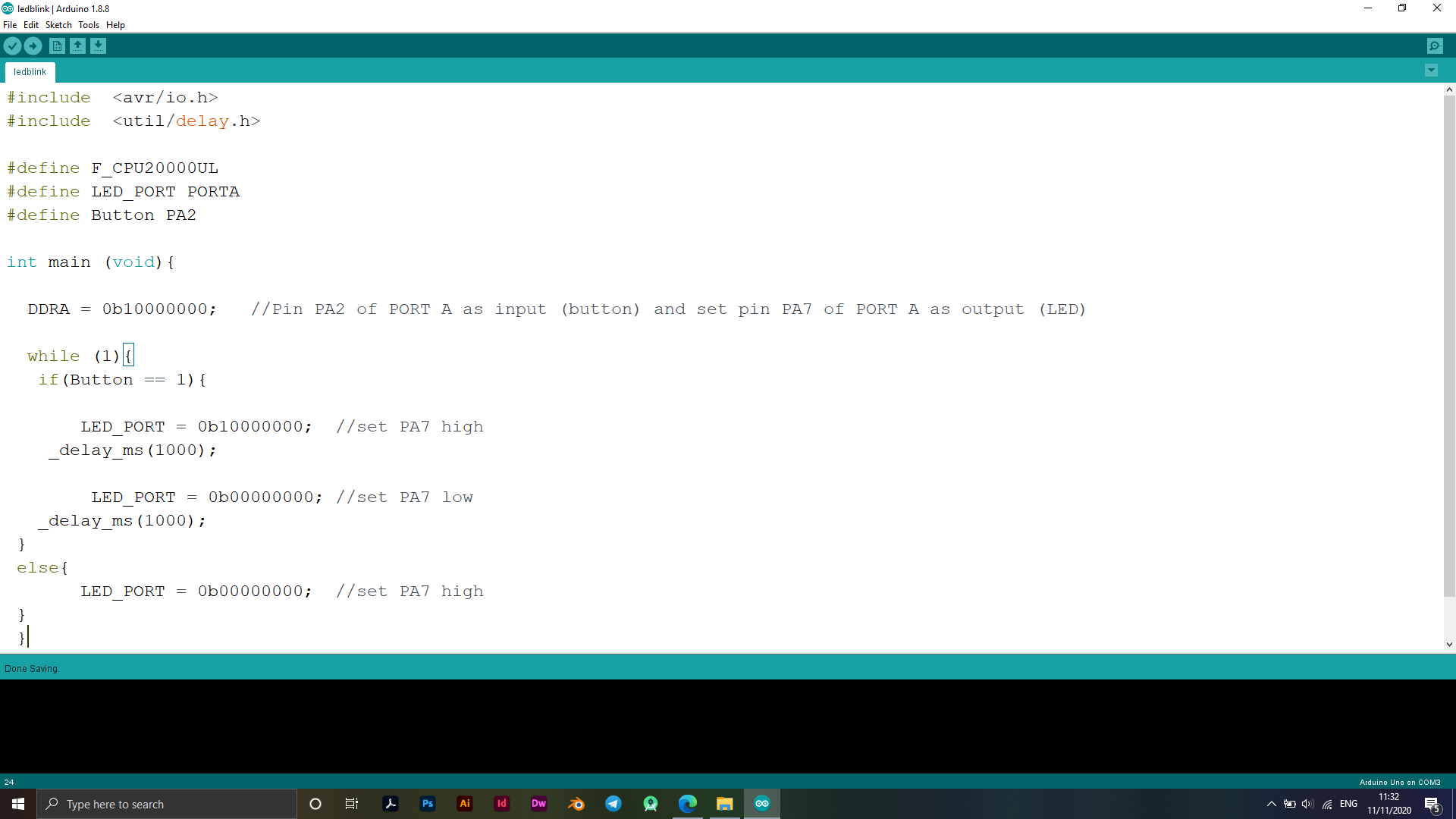
The code below shows the change process that took place as I chose the PIN name in the code differently from the Arduino code, I converted the code to the C language, where I considered that the LED port is port No. 6 and according to Datasheet ATtiny44 it is port No. 6 which you have specified as the port For the LED labeled PA7, when navigating to the code I set code line DDRA = 0b00000001; Where we consider DDRA is the designation through which the port number is called and the other suffix the PIN number, in the electronic board that I designed the LED port comes with the number PA7, meaning that after eight zeros starting from PA0.
The lower part of the code you set the first time to output, meaning that the Switch will turn on the LED once and in the other part it will turn it off (HIGH - LOW), this is set by controlling zeros, where the number 0 refers to turning off the LED while the number 1 is to turn on the LED, The following image shows the order of the code.
C Code
#include  <avr/io.h>
#include  <util/delay.h>

#define F_CPU20000UL
#define LED_PORT PORTA
#define Button PA2

int main (void){

DDRA = 0b10000000;//t Pin PA2 of PORT A as input (button) and set pin 2 of PORT A as output (LED)


while (1){
if(PA2==1){

LED_PORT = 0b10000000;  //set PA7 high
_delay_ms(1000);

LED_PORT = 0b00000000; //set PA7 low
_delay_ms(1000);

}
else{

LED_PORT = 0b00000000;  //set PA7 high


}
}
}
Fuse Calculator
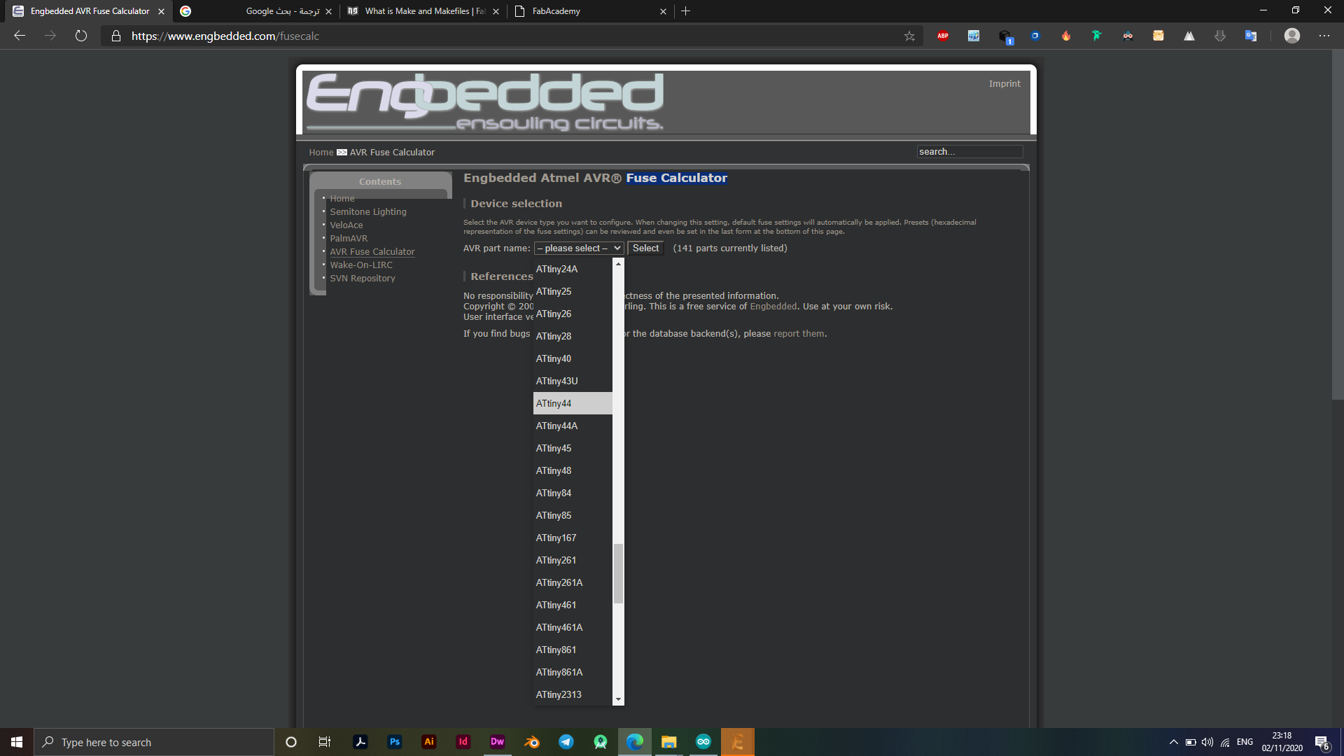
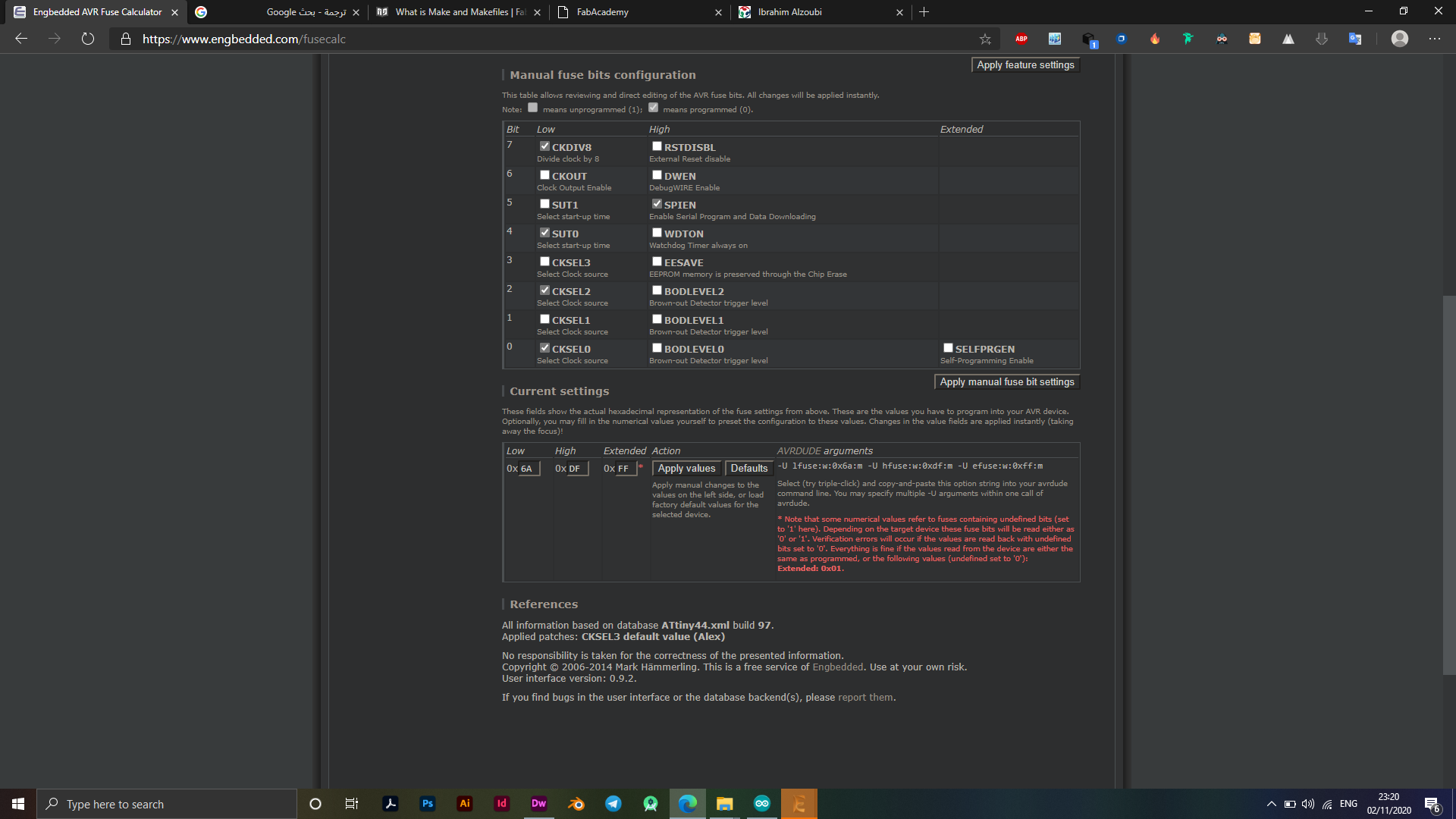
I did the fuse calculation process through Engbedded, through the site I calculated the fuses for the ATtiny44 microcontroller that I use on the electronic board, see the pictures below. pic1
What we are interested in in this process is the LOW value of the fuse, which appears in image 0x6a. pic2
Members of the AVR family may have one or more Fuse Bytes. How many there are, and what they do, depends on the specific microcontroller Reading the datasheet for AVR micros, with a "1" means that it is not programmed while a "0" is considered to be programmed following the tutorial ( link below) I used avr fuse calculator just to know more about fuses avr fuse calculator which shows this default configuration "Engbedded"
I used This Page to learn more about how to choose which value the Fuse should contain
Create Make File
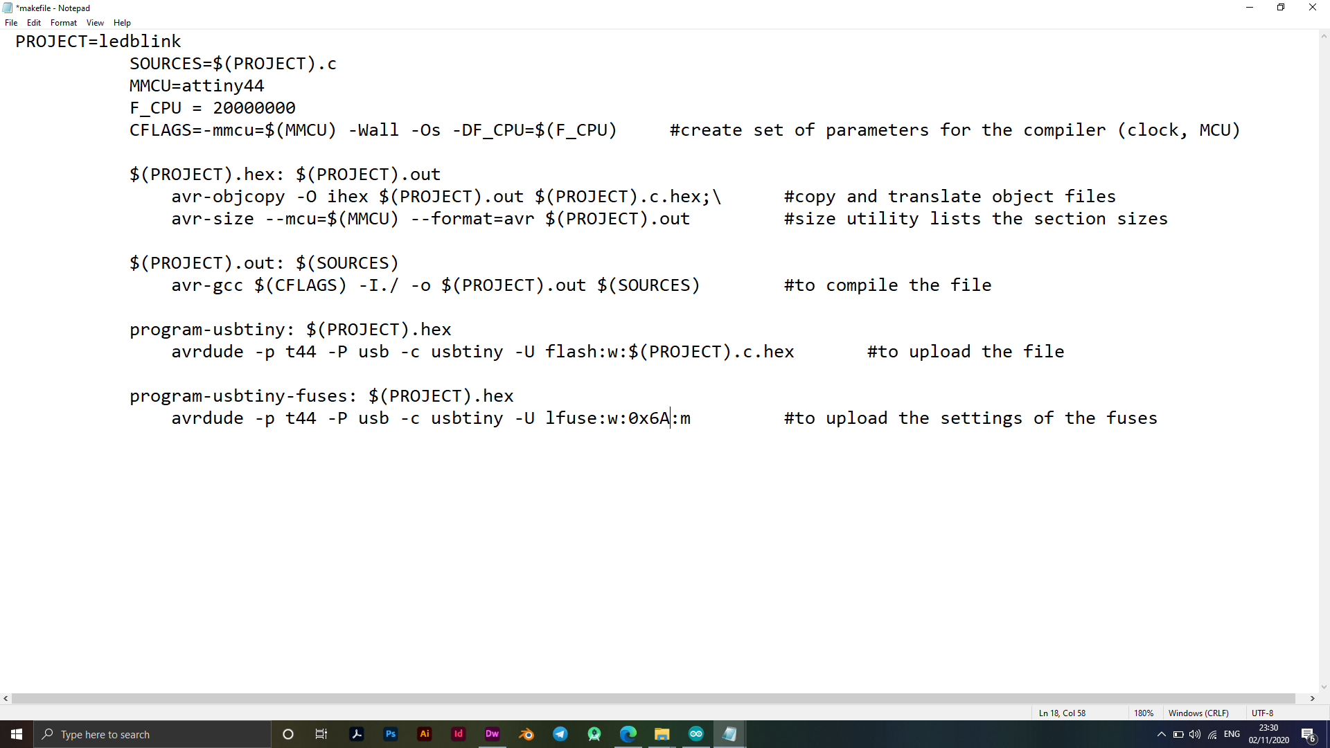
To create a tablet programming Makefile, I used Neil’s Makefile, then modified and deleted what was appropriate for my electronic tablet programming process. I deleted some unimportant lines in addition to changing the fuse value that I calculated in the previous step, see the following image.
Make File
PROJECT=ledblink
SOURCES=$(PROJECT).c
MMCU=attiny44
F_CPU = 20000000
CFLAGS=-mmcu=$(MMCU) -Wall -Os -DF_CPU=$(F_CPU)     #create set of parameters for the compiler (clock, MCU)

$(PROJECT).hex: $(PROJECT).out
avr-size --mcu=$(MMCU) --format=avr $(PROJECT).out         #size utility lists the section sizes

$(PROJECT).out: $(SOURCES)
avr-gcc $(CFLAGS) -I./ -o $(PROJECT).out $(SOURCES)        #to compile the file

program-usbtiny: $(PROJECT).hex
avrdude -p t44 -P usb -c usbtiny -U flash:w:$(PROJECT).c.hex       #to upload the file

program-usbtiny-fuses: $(PROJECT).hex
avrdude -p t44 -P usb -c usbtiny -U lfuse:w:0x6A:m         #to upload the settings of the fuses
Ubuntu
In this step, the Ubuntu system must be installed to program the electronic tablet on it through several commands that are applied through the default program added in the system by default, "Terminal". After installing and opening the Ubuntu system, we open the "Terminal" program through the application panel in the bottom, or use the option to search for the program، Install Ubuntu
When writing the code in C language and creating a Makefile, the formulas are removed from the files.
I connected my Board to the tablet I designed at Electronics Productions Week, through an ISP
Connections EchoHello with my Board
Steps Ubuntu
- sudo apt-get install flex byacc bison gcc libusb-dev avrdude
- sudo apt-get install gcc-avr
- sudo apt-get install avr-libc
- sudo apt-get install libc6-dev
You can see my terminal log, Click Here
Terminal Log
x-special/nautilus-clipboard
copy
file:///home/yazan/Desktop/files
yazan@YazanPC:~$ cd Desktop/files/
yazan@YazanPC:~/Desktop/files$ ls
ledblink.c makefile
yazan@YazanPC:~/Desktop/files$ make
avr-gcc -mmcu=attiny44 -Wall -Os -DF_CPU=20000000 -I./ -o ledblink.out ledblink.c
avr-objcopy -O ihex ledblink.out ledblink.c.hex;\
avr-size --mcu=attiny44 --format=avr ledblink.out
AVR Memory Usage
----------------
Device: attiny44
Program: 64 bytes (1.6% Full)
(.text + .data + .bootloader)
Data: 0 bytes (0.0% Full)
(.data + .bss + .noinit)
yazan@YazanPC:~/Desktop/files$ make program-FABISP
avr-objcopy -O ihex ledblink.out ledblink.c.hex;\
avr-size --mcu=attiny44 --format=avr ledblink.out
AVR Memory Usage
----------------
Device: attiny44
Program: 64 bytes (1.6% Full)
(.text + .data + .bootloader)
Data: 0 bytes (0.0% Full)
(.data + .bss + .noinit)
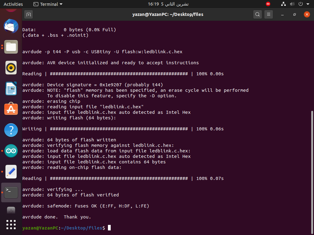
avrdude -p t44 -P usb -c USBtiny -U flash:w:ledblink.c.hex
avrdude: AVR device initialized and ready to accept instructions
Reading | ################################################## | 100% 0.00s
avrdude: Device signature = 0x1e9207 (probably t44)
avrdude: NOTE: "flash" memory has been specified, an erase cycle will be performed
To disable this feature, specify the -D option.
avrdude: erasing chip
avrdude: reading input file "ledblink.c.hex"
avrdude: input file ledblink.c.hex auto detected as Intel Hex
avrdude: writing flash (64 bytes):
Writing | ################################################## | 100% 0.06s
avrdude: 64 bytes of flash written
avrdude: verifying flash memory against ledblink.c.hex:
avrdude: load data flash data from input file ledblink.c.hex:
avrdude: input file ledblink.c.hex auto detected as Intel Hex
avrdude: input file ledblink.c.hex contains 64 bytes
avrdude: reading on-chip flash data:
Reading | ################################################## | 100% 0.07s
avrdude: verifying ...
avrdude: 64 bytes of flash verified
avrdude: safemode: Fuses OK (E:FF, H:DF, L:FE)
avrdude done. Thank you.
yazan@YazanPC:~/Desktop/files$
After completing the installation of the offices and using the above commands, I created a Makefile by entering the file location via the Terminal "Cd / XXXXXX" command prompt, then I created the Make command and then, Make in addition to the suffix that was selected in the Makefile, make program-FABISP
Download Files
Terminal LogMake File
ledblink - hex - out
Led Blink Code.C