Computer-Controlled Machining
In the seventh week of Fab Academy, we learned to cut wood through CNC machine, which is called ShopBot, where we were able to cut the wooden boards through this machine. At first, I made the design that I want through the Fusion 360 program, then I moved to the dedicated machine to cut the wood panels. "ShopBot".
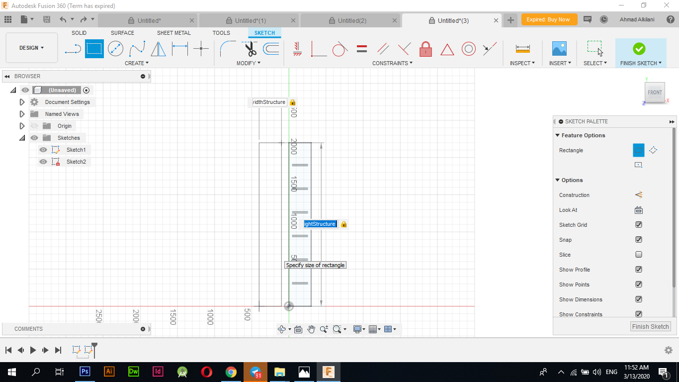
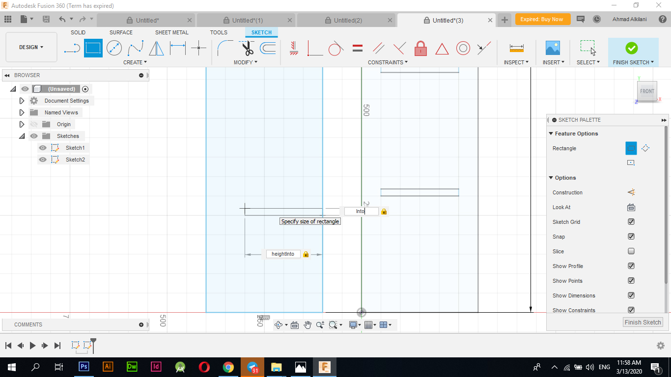
Design by Fusion 360I drew a rectangle with random dimensions at first
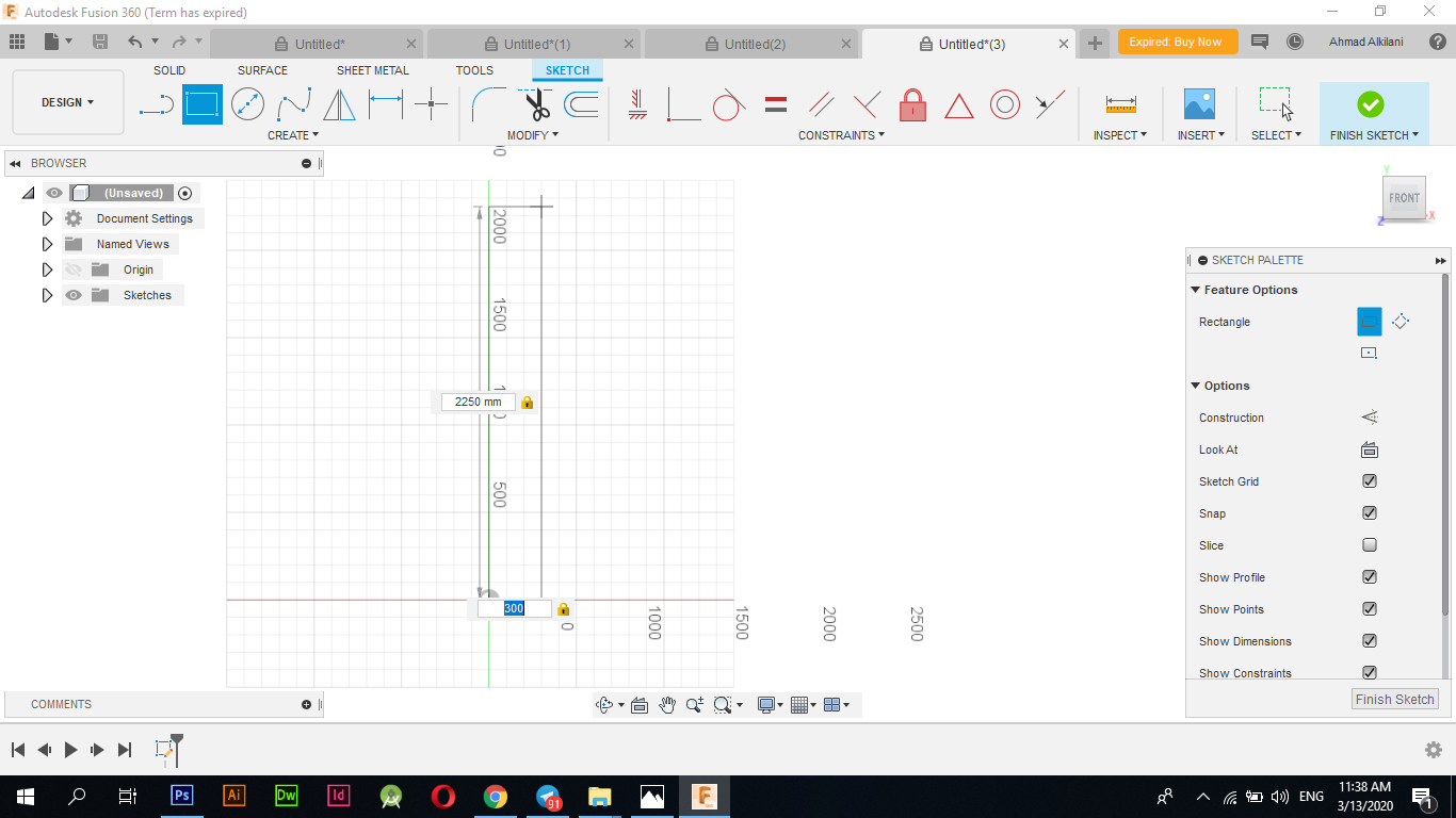
It was mentioned in the lecture that the design must be based on the "Parametric" proportionality, which states that all drawn sides must be proportional to each other, that is, if one side of the design is changed, the other must change so that the ratio between them becomes equal. More: The word 'parametric' is used to describe methods in math that introduce an extra, independent variable called a parameter to make them work. For example, consider the parametric equations of a circle. The circle is defined this way using two equations.
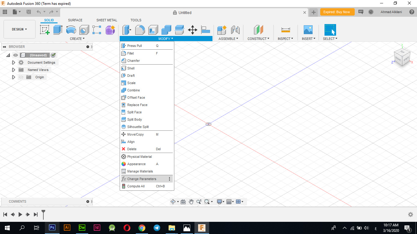
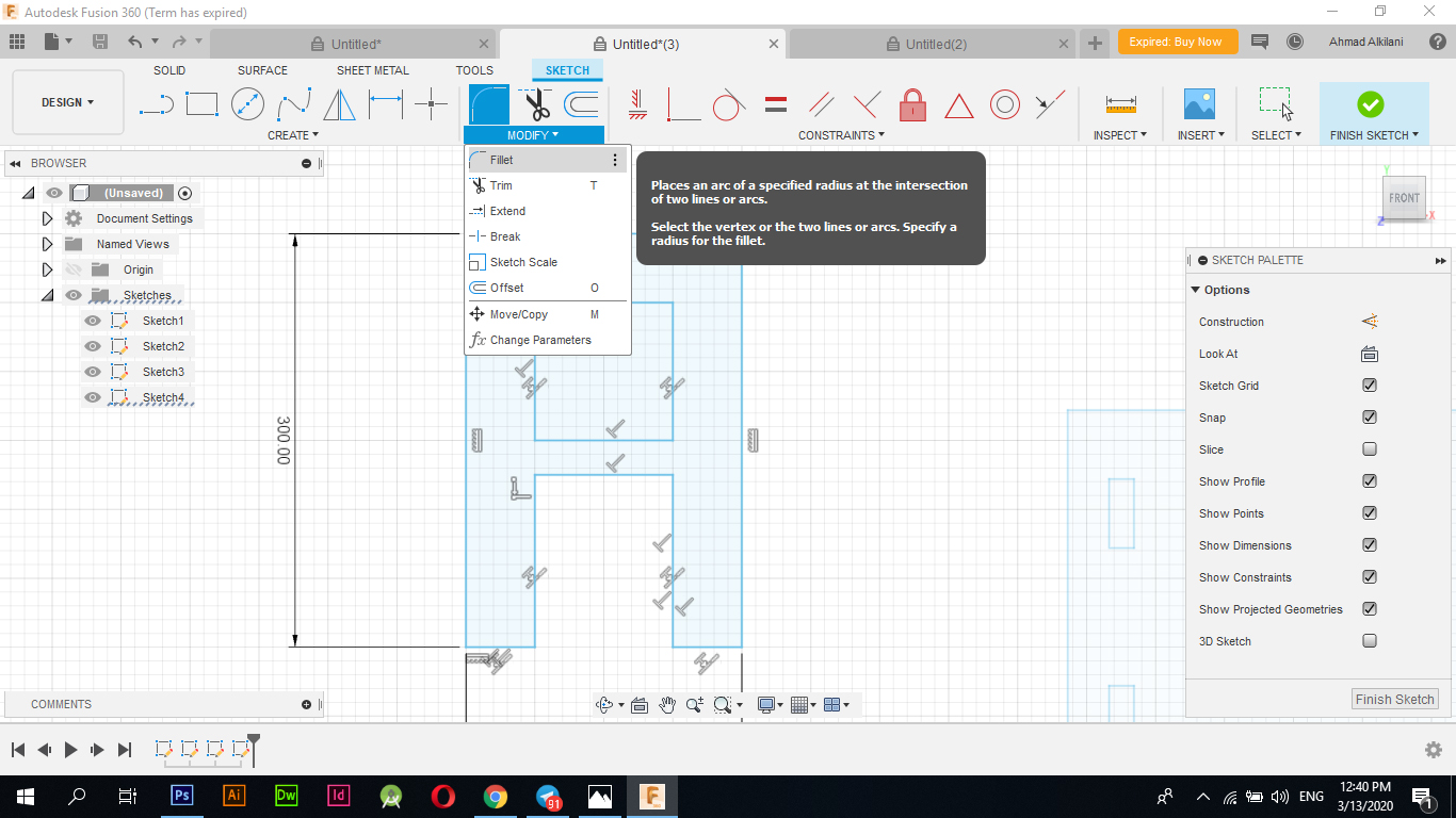
To set the design for this feature I went to "Modify - Change Parameters" and added a new option and set the percentage that I want to connect it later to this side that I want to change.
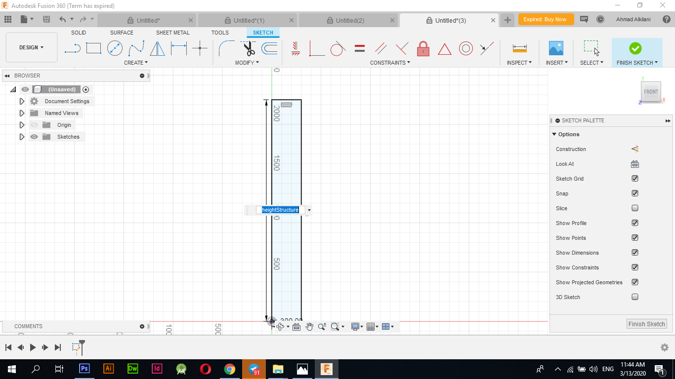
Now I reset the size of the side that I drew by re-editing the size and choosing the command that I set in the "Change Parameters" tab where I chose "heightStructure" and placed a measurement of "2000mm" which is two meters, to set that command and link it to the side you need to choose the command in a rectangle Measurements for the ribs, that is, instead of setting "2000mm", I set the command that I attached in the "Parameterec" interface, which is "heightStructure". Once I type only one letter, all the orders I placed automatically appear for me, so I specify "heightStructure" and I give it consent to link.
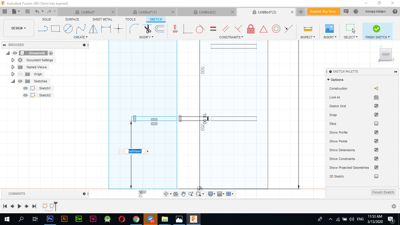
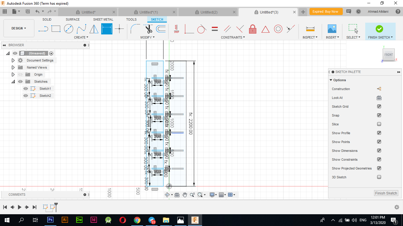
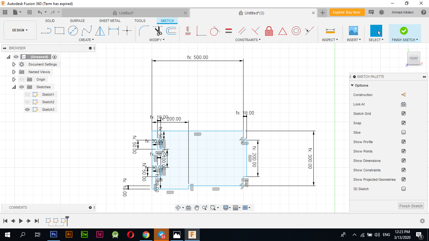
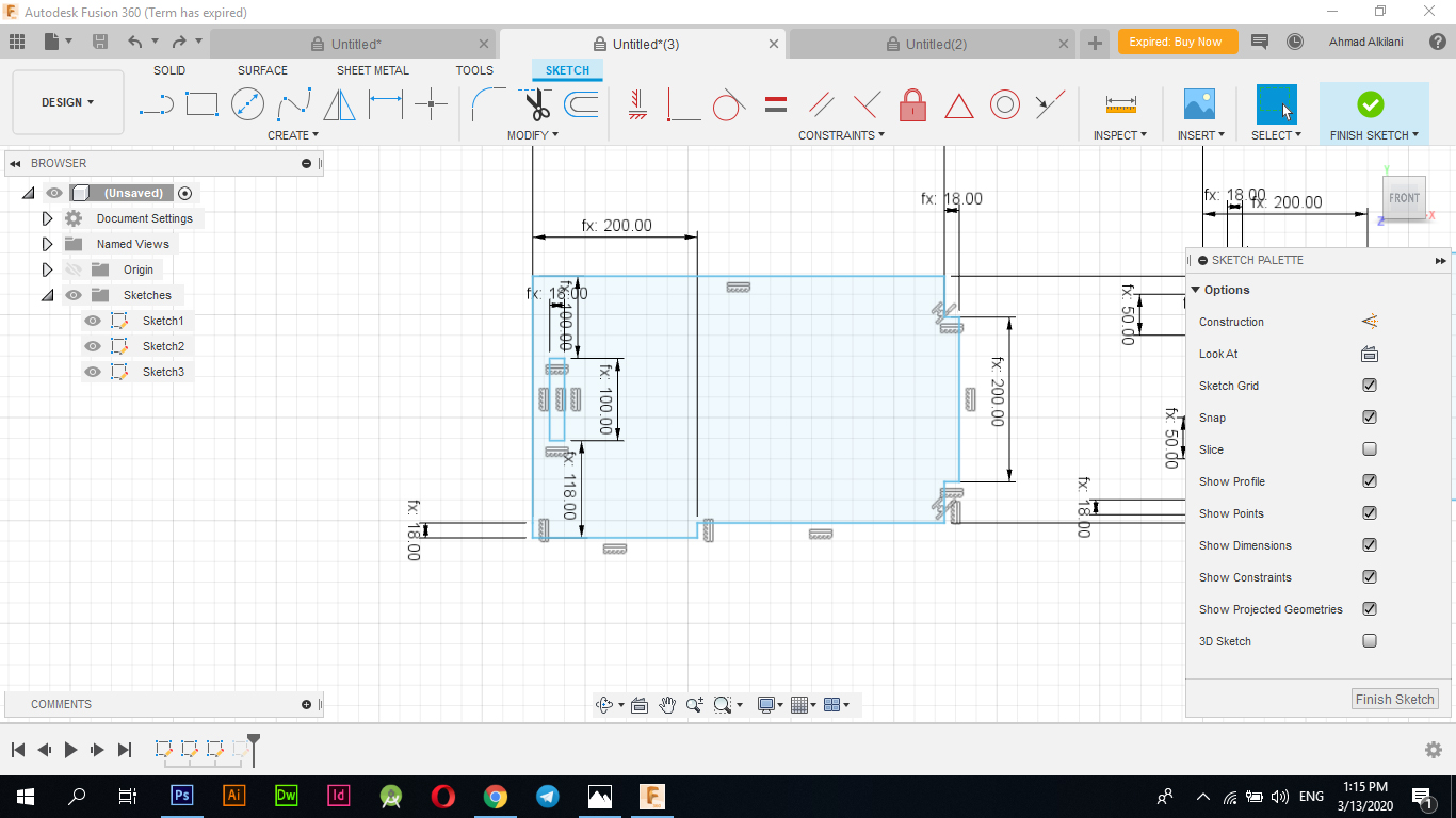
After I finished drawing the outer frame and linking it with the orders I wanted to maintain the proportion of proportionality between them I also drew small rectangles with a height of "18mm" and a width of "200mm" I also linked them with several orders to maintain the ratio between them in the same way that I mentioned above I also linked and drawn Rectangles, in this case I had to link length and width as well as in the outer frame so I added two things, one measuring "18mm" which is the height of the wood I used in the cutting process and the other with a width of "200mm" I chose this width based on what I saw as appropriate for the design if I wanted to install the design Finally finished without using any other metal moda or fixings like screws, nails, SuperGlow and the like
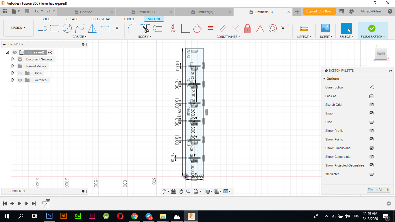
At this point I drew another rectangle similar to the first rectangle that I drew, I also set the same dimensions for it by using the same commands for the second rectangle that I drew again instead of placing new orders and since the design should be in Parametrec format so I used the same commands for the first drawing I also drew rectangles with the same dimensions inside this rectangle, but in this case the rectangles were at the end of the lines, that would not affect the orders, so I also used those commands in the one that I used for the first rectangle only what differs from them is the place and this does not affect the process of proportionality between them or It might Vandalism on both drawings.
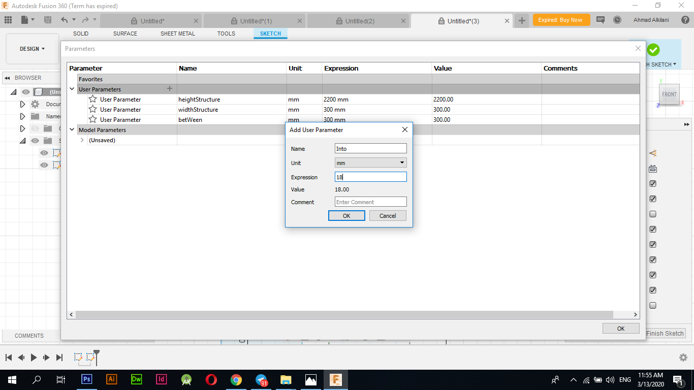
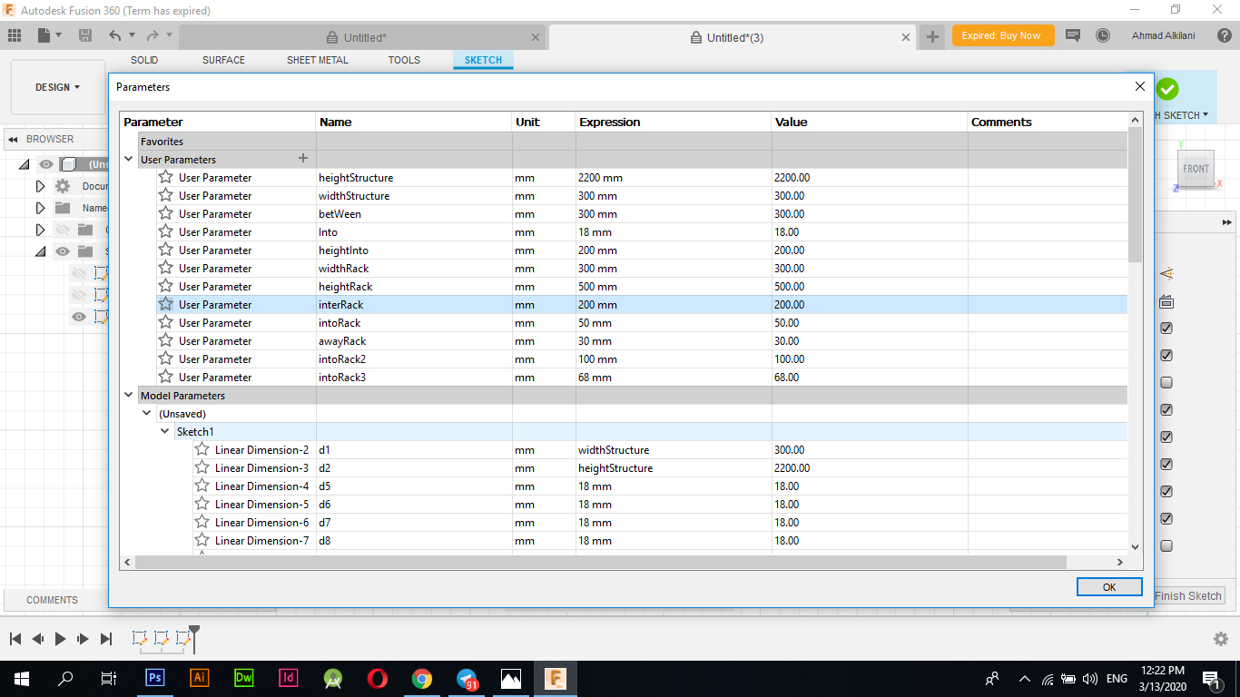
How to use Parameterec interface
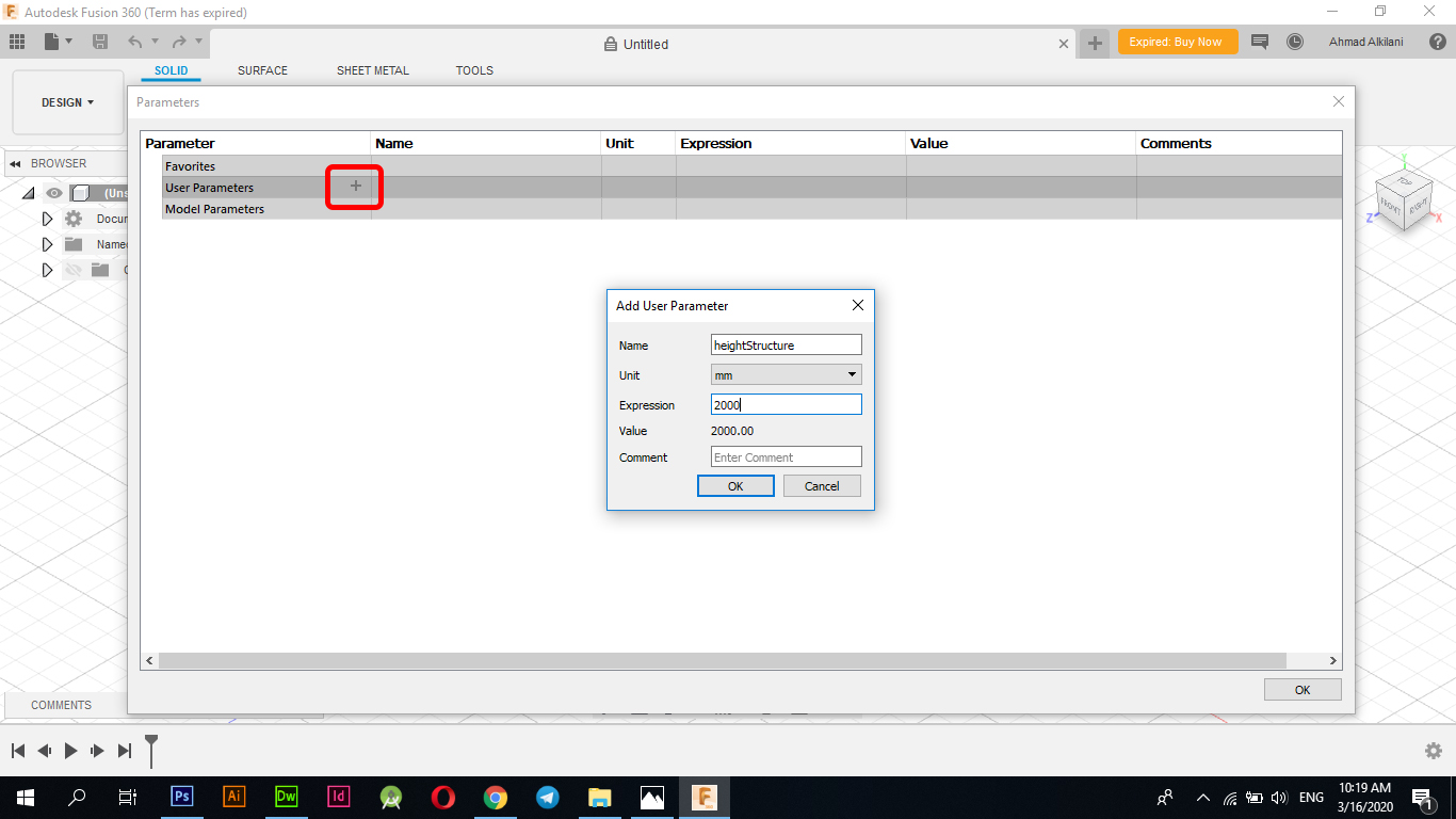
Initially, I was able to access this interface by going to "Modify - Change Parameters" The "+" sign appears in the image below, through which I was able to add a new command and link it to the ribs or drawings that I will draw, in the first rectangle and after clicking on the plus sign "+" "I was asked to add a name to the order here. I can choose whatever names you like, but it is preferable to put a name so that I know for what side this will be. In the next option, I will be asked to choose the unit you want to work on. I chose the unit of" mm ", and then I had to choose the size. For this matter, for example, I set the "2000mm" measurement for the first order, and this is the size I wanted when making my plan. As it appears in the image below, I have set several custom commands, all of which will work on the ribs I am selecting, but I have added all the commands one time for relaxation during the design as they do not disperse the designer and are ready. I just linked directly instead of setting measurements and then reconnected again.
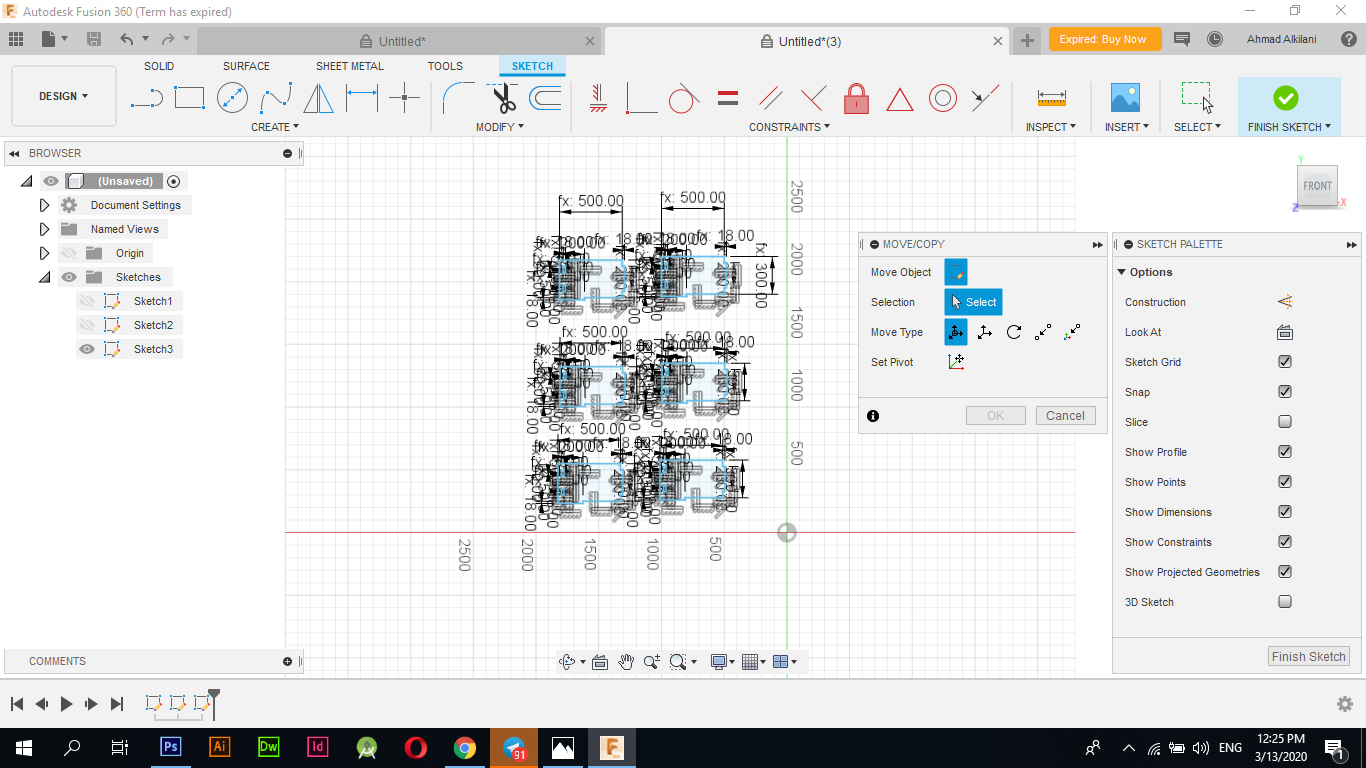
After I finished the external frames and sides and linked them all to the Parametrec orders, I started to draw the shelves or the surfaces where I used the "Line" option from the "CREATE" menu and started to draw the dimensions directly as well. I link them to the orders that I assigned them, and as it appears at every sign the letter "fx" Which indicates that it is linked to Parameters options and I have repeated it in six copies through the option of “Move / Copy” I chose “Sketches” and started copying.
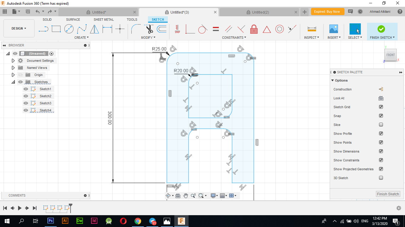
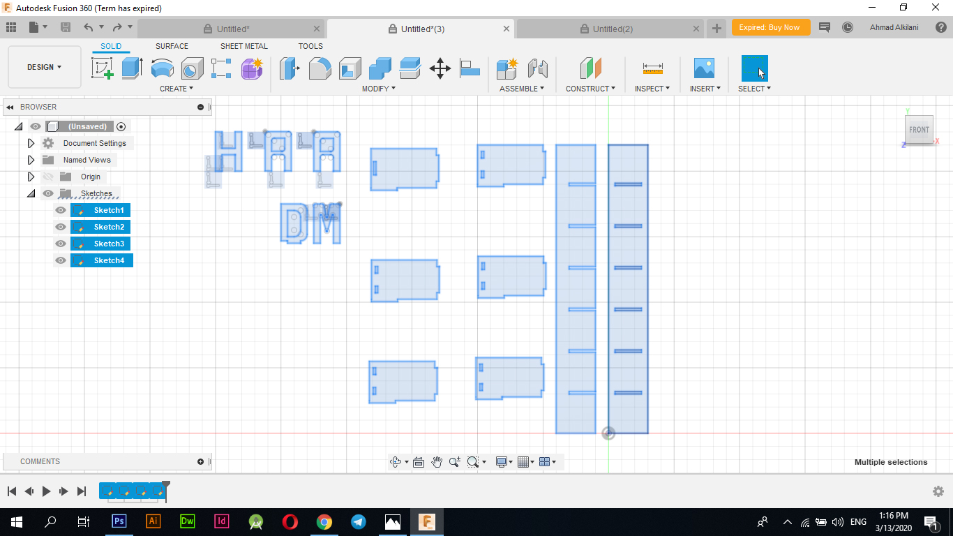
I decided to use the letters my name "AHMAD" and put them on the design to add more aesthetic or to complicate the design a bit so I drew the letters "A - H - M - A - D" through the line drawing tool as shown in the following pictures the drawing process "Note: I did not use Parametrec options in character design as it consumes a lot of time also I don't think it will be appropriate because the character design contains a lot of angles and oblique zigzags which may cause problems but I just drew the letters in an attractive and wonderful way, "I also used the Fillet tool to add more aesthetic to Character form got the tool through "Modify - Fillet" and it started catching Between the two angles that I want to make a curve to the angle between them automatically and the tool will make a curved angle between them also I made different angles in the measurement Some of the angles I made a curvature of them by half a centimeter and others by a quarter of a centimeter and many other measurements that correspond to the shape of the letter.
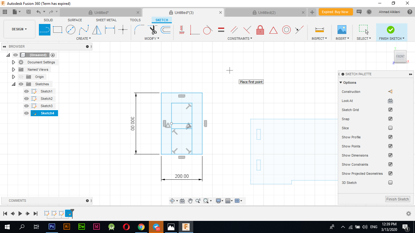
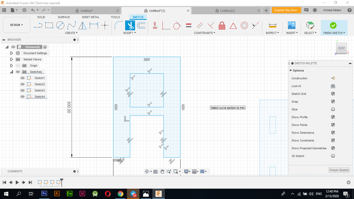
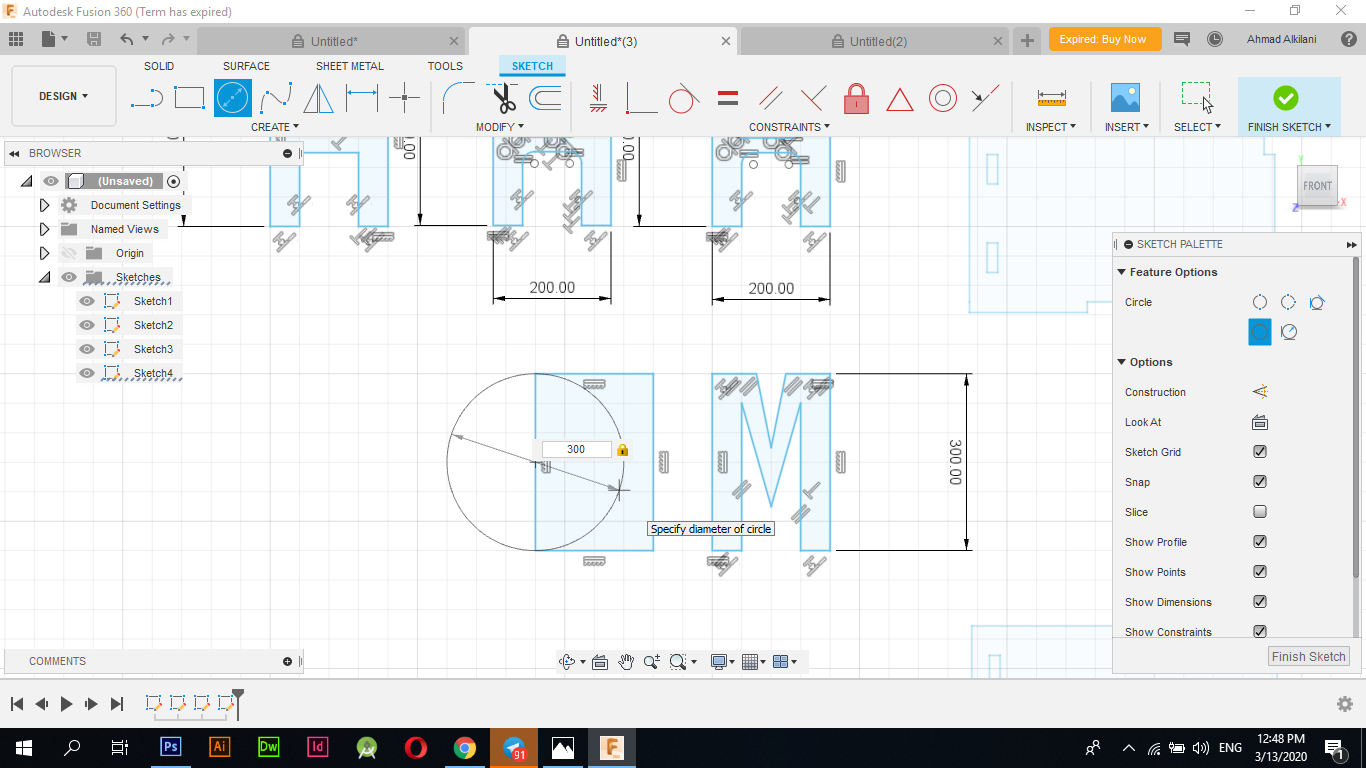
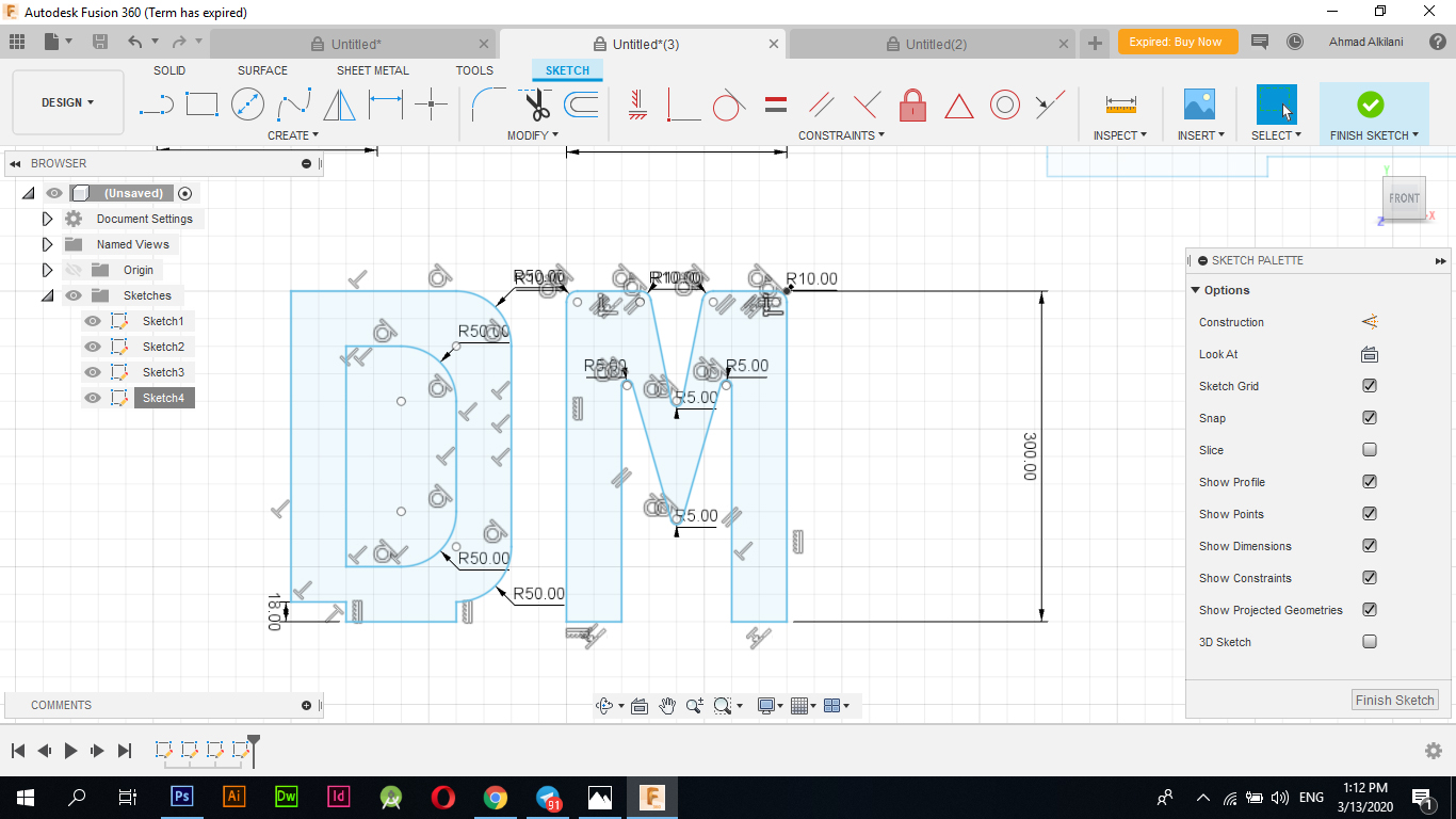
In the following picture, I had to adjust one of the shelves to match the letter D, as the letter D changed the place for attaching it to the shelf, so it appears that it takes an "100mm" space at the bottom, unlike the other letters on both ends through the legs as it is in the letters "A - H - M" has legs. From below I could not show the letter "D" in the same shape because it is expected that its shape will appear distorted.
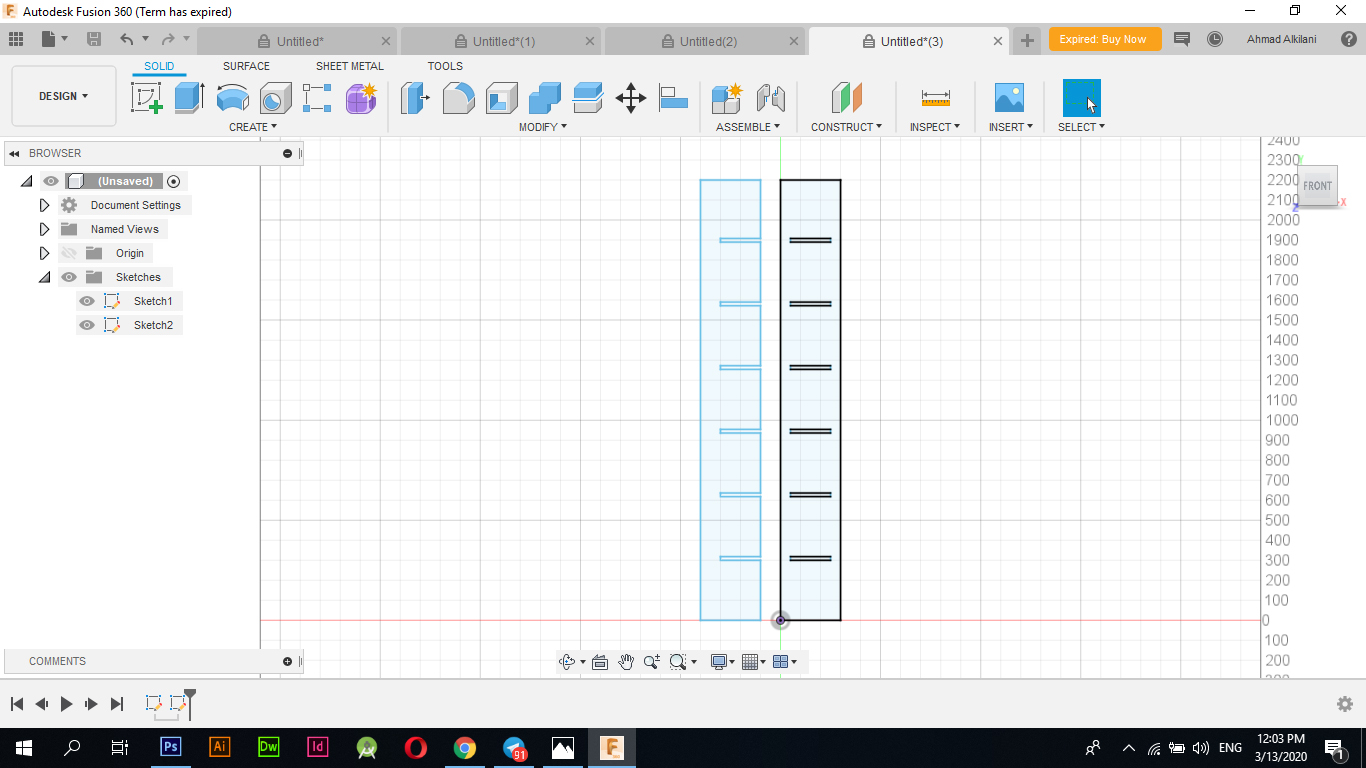
In the picture, his self shows all the layers that I designed and this is the final form of the design
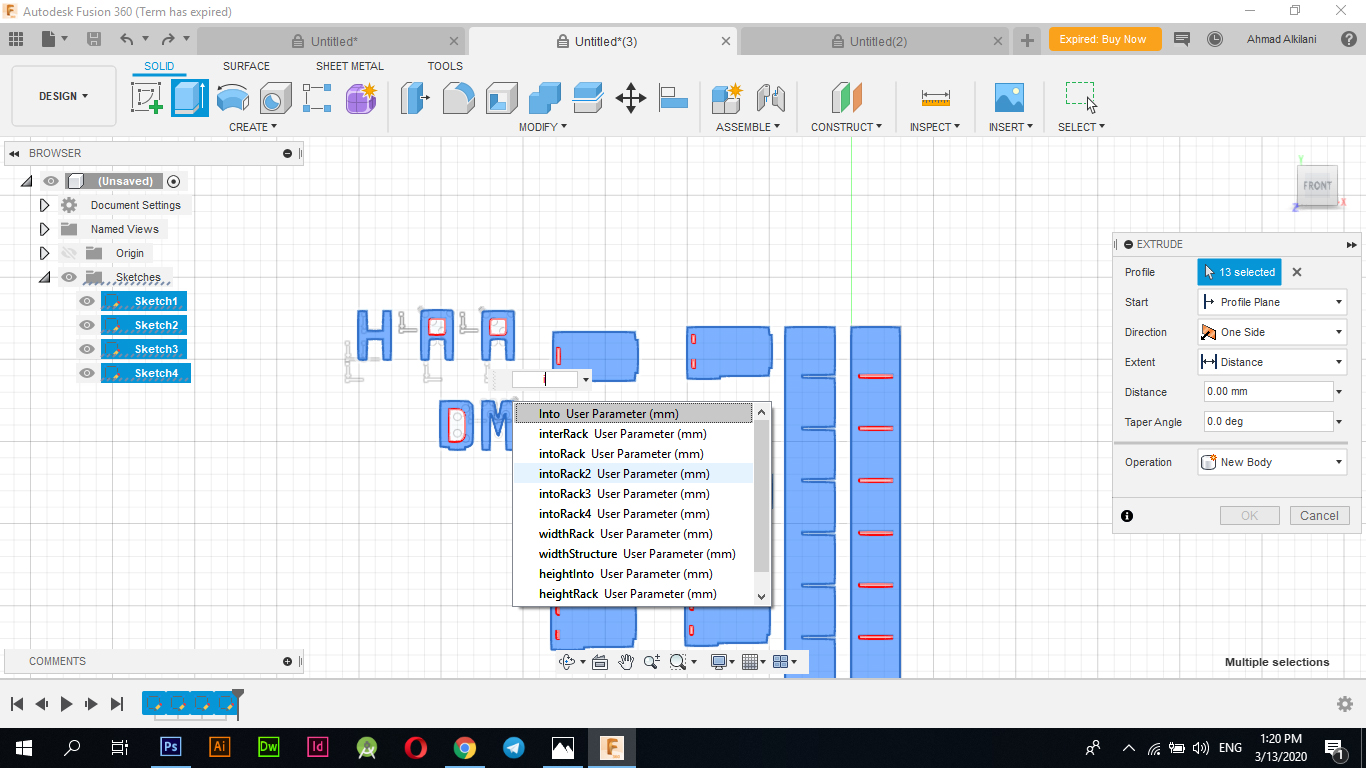
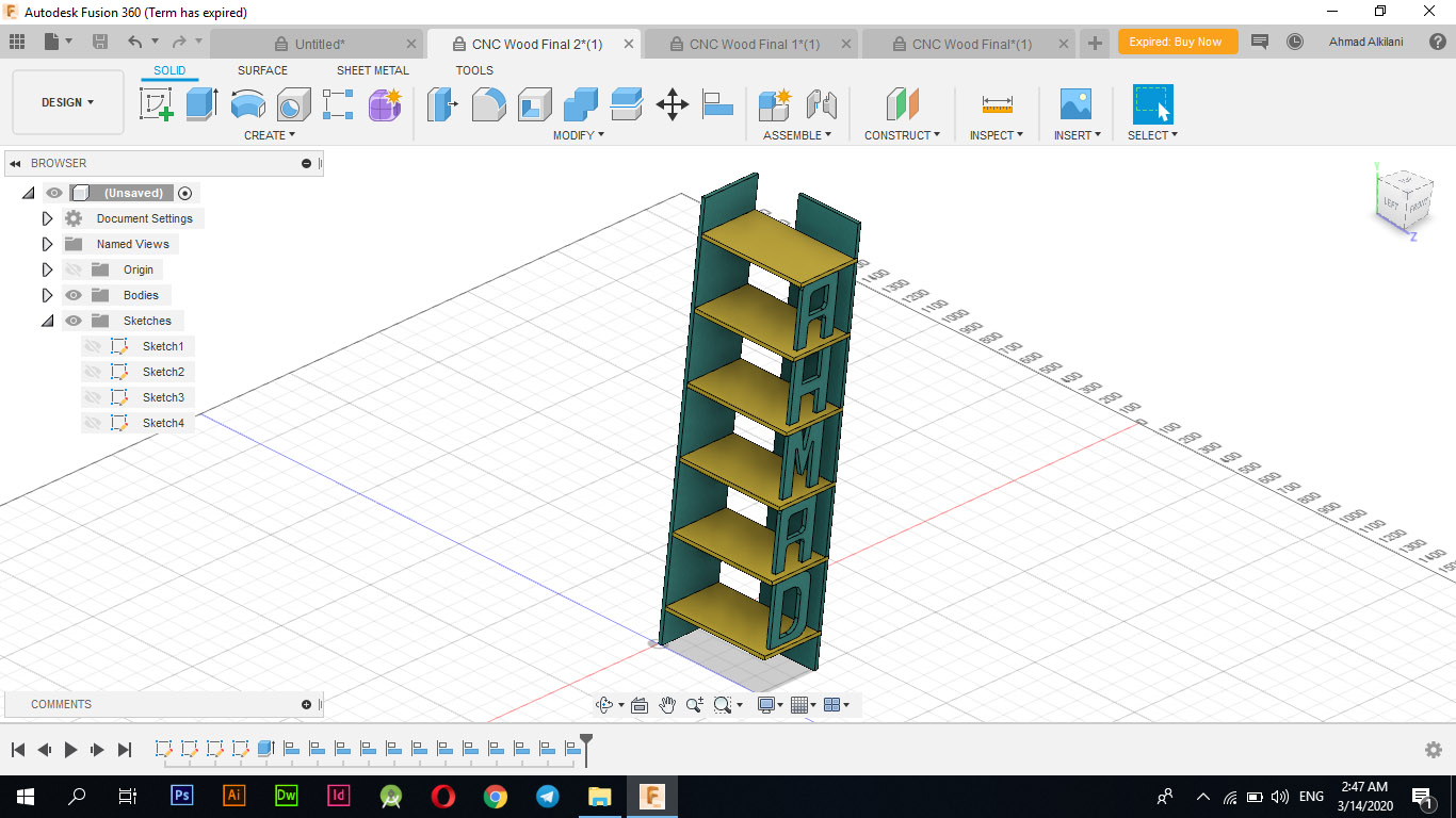
I made "Extrude" for the design in preparation for installing it on one another through "Fusion 360" and to see it in a clearer voice. Three-dimensional I chose to install the pieces on each other through "Modify - Align" and I started to challenge the angle on the appropriate angle to it and the two pictures below show the process of converting the shape to three dimensions and the shape also after installing it on each other, and to give the design more aesthetic and see it more clearly also I made Wooden colors for him and appear in the most beautiful appearance of these colors Through the Apperance option I then chose the theme I wanted and installed it on the pieces
VCarve
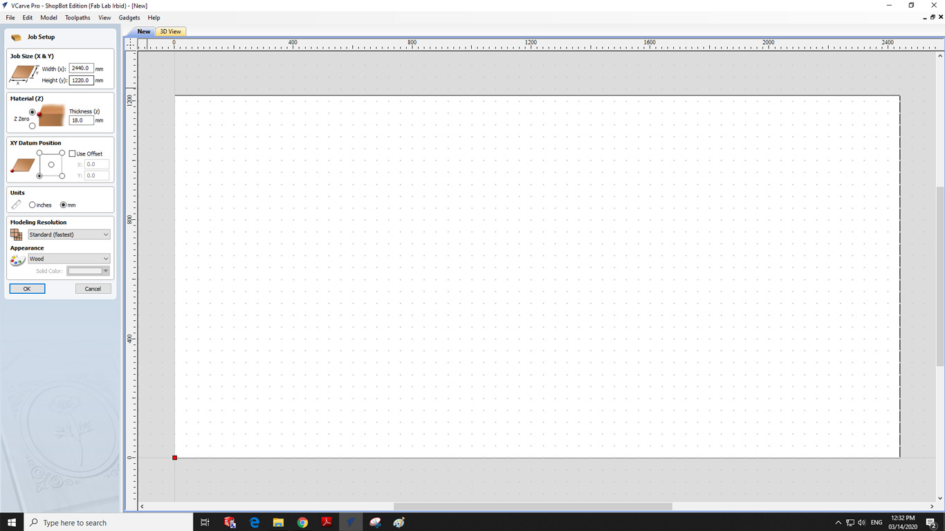
I have used the "VCarve" program as it is the program that we usually use in the process of cutting on "ShopBot", so I opened the "VCarve" program and created a new project and set these settings as they are in the following image as a measure of the wood plank that I will use, the type of wood, the height, height, and location of the cutting.
| Mission | Size Or Type |
|---|---|
| Width | 2440mm |
| Height | 1220mm |
| Thikness "z" | 18 mm |
| Unite | Millimetre "mm" |
| Wood Type | PlyWood |
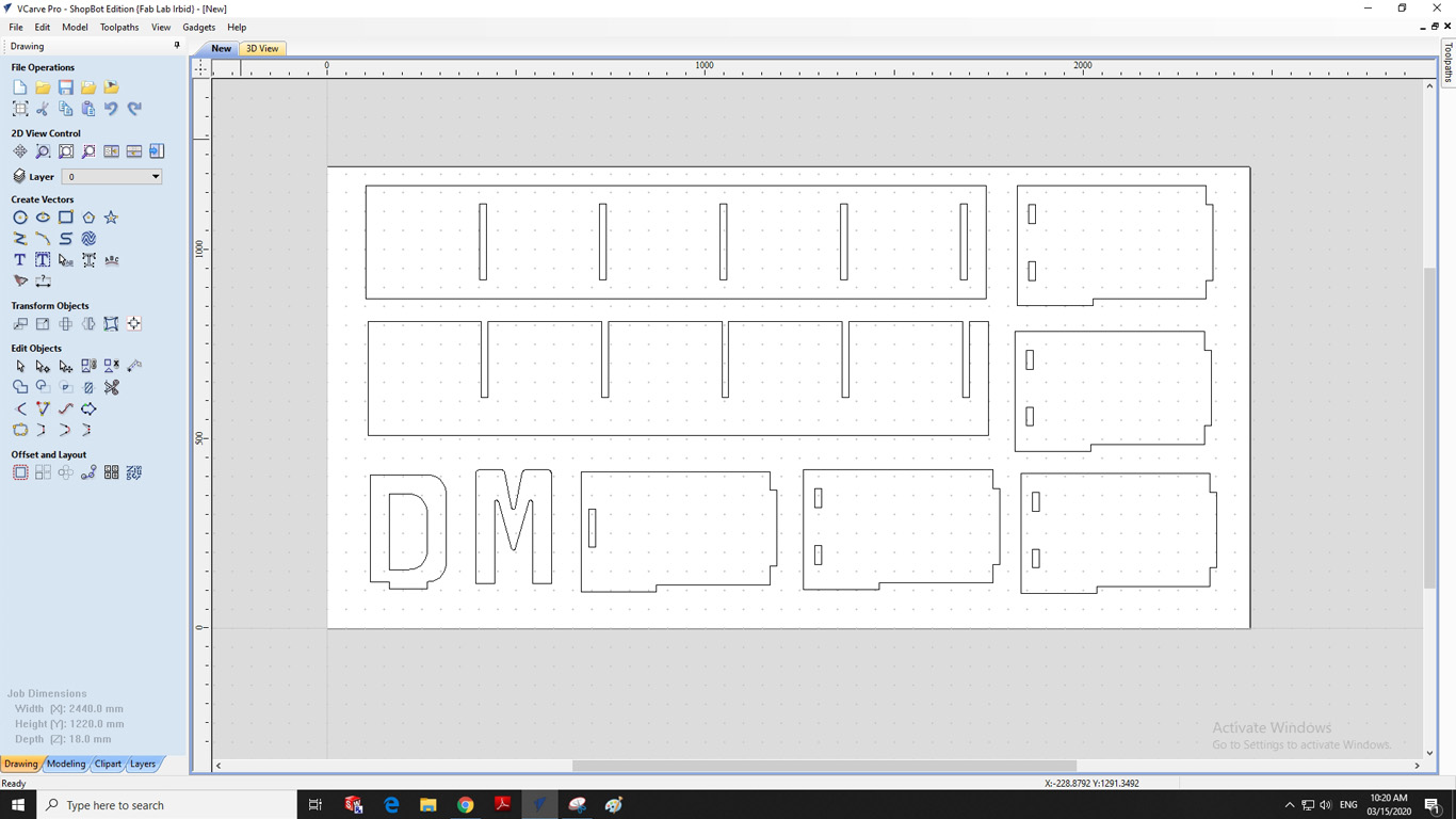
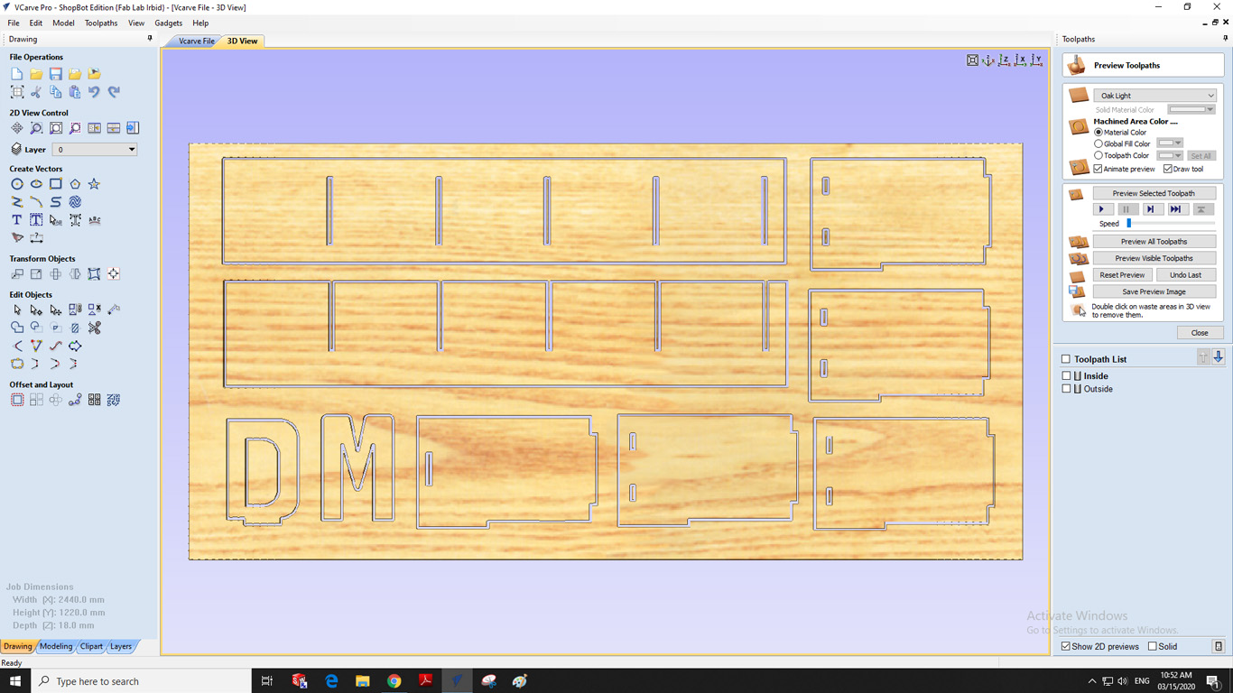
After that I added my design to the program and arranged the layers to be appropriate on the board and cutting and to make sure that the sides may not be affected or that the plate is sufficient for the cutting process as noted in the arrangement in the following image, and that a simple distance of "5mm" should be left as a minimum for the process Shear To ensure that the shear does not occur in the air, which may cause problems during the shear process or may cause the feather to break, we must therefore comply with the hammers as much as possible and leave a slight distance for them.
Border Settings
The boundaries that require that you have chosen mostly all the squares and rectangles that are inside the outer frames or I can say that are included within the designs must be Inside to ensure that the cut is not done incorrectly and thus the unnecessary result will be produced for you if I choose OutSide will cause a problem that it will not Shearing is within the required limit, but the blade will cut and widen the opening further by the size of the blade that is being worked on, and do not forget about shear settings such as Cut Depth. I chose it by "20mm" with an increase of "2mm" to ensure that the shuttlecock cuts appropriately without leaving any Other connections.
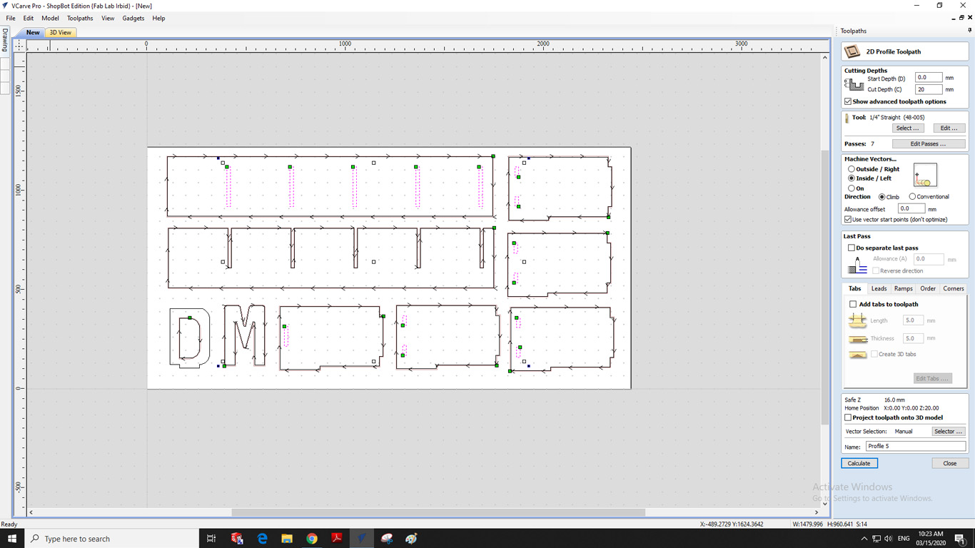
Here also I selected the fonts that I want the machine to cut, so if we notice that I choose OutSide because if I choose the other option InSide the machine will cut from inside the board and this is what I don't want as I want the machine to cut the borders that I chose so ask me to do so If I choose OutSide, I also chose Cut Depth by "20mm" with an increase of "2mm" to ensure that the machine will cut without leaving any connections between the plate and the pieces that have been set for cutting. I also chose the blade by "1/4" during the cutting process, I did not need To place Tabs between the plate and the cutting itself, the machine took "48" minutes to finish cutting.
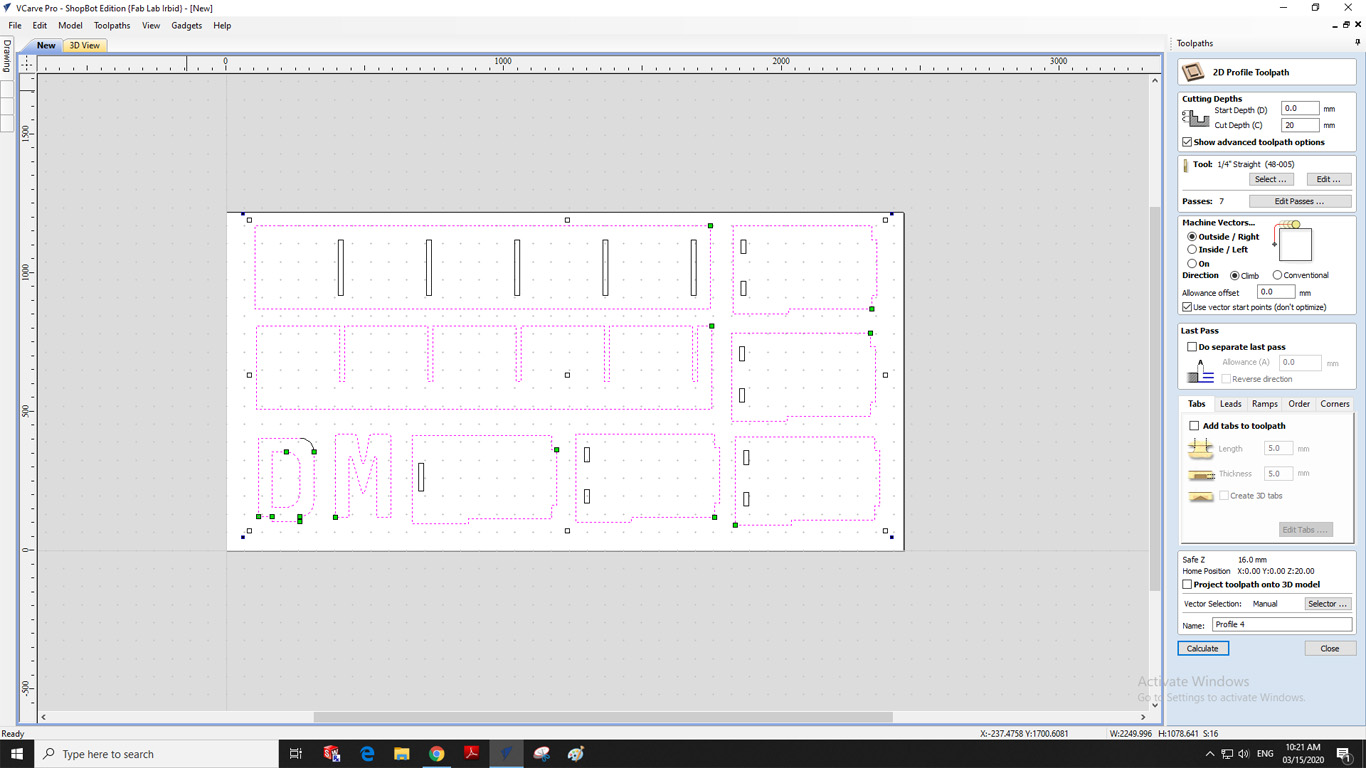
The following image shows the design in 3D format, as it shows the passage of the feather and where you will cut from here. We can determine whether the feather will affect the other pieces or not, as it appears to us that all the pieces are far apart and there will not be any problem during cutting، The following image shows the design in a three-dimensional format as it shows the passage of the feather and where you will cut from here. We can determine whether the feather will affect the other pieces or not. As we show that the pieces are all spaced and there will not be any problem during cutting, now it remains to do Save the design, go to "ShopBot 3" and notify the cut command.
Setting up the machine
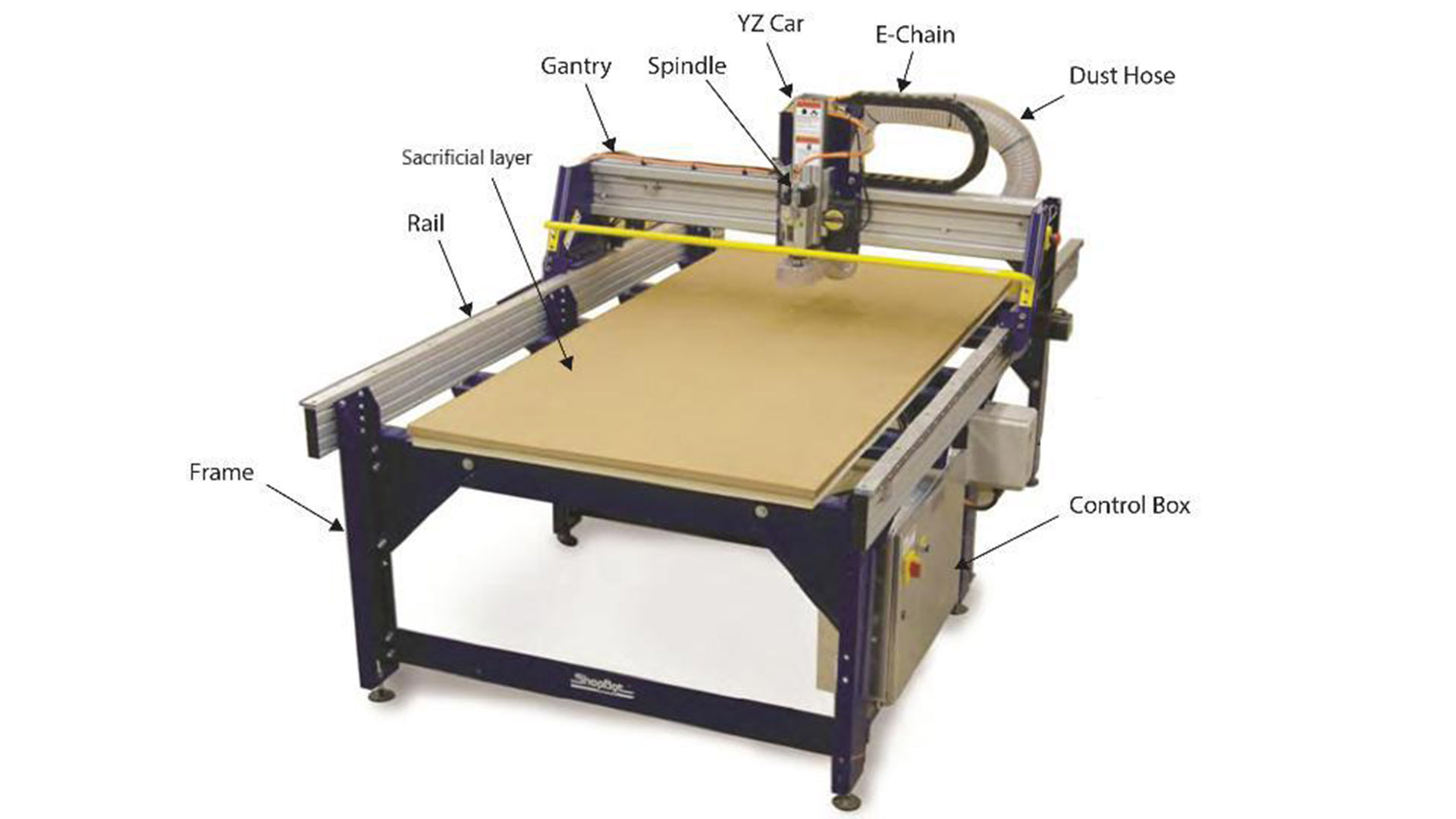
Firstly, we have to ensure that the workbench is clear and place our plywood on to the workbench, Check the levels of the plywood and screw it to the sacrificial layer to prevent rattling of the material after cutting, After turn ON the machine from the control box,and a shopbot control window appears.We can move the head in XY direction.
In our FabLab we have Shopbot PRSalpha model which has a bed size of 96 inch x 48 inches.It is the biggest machine in our Fablab and has a vacuum system as well as a dost collecting chamber attatched with it.
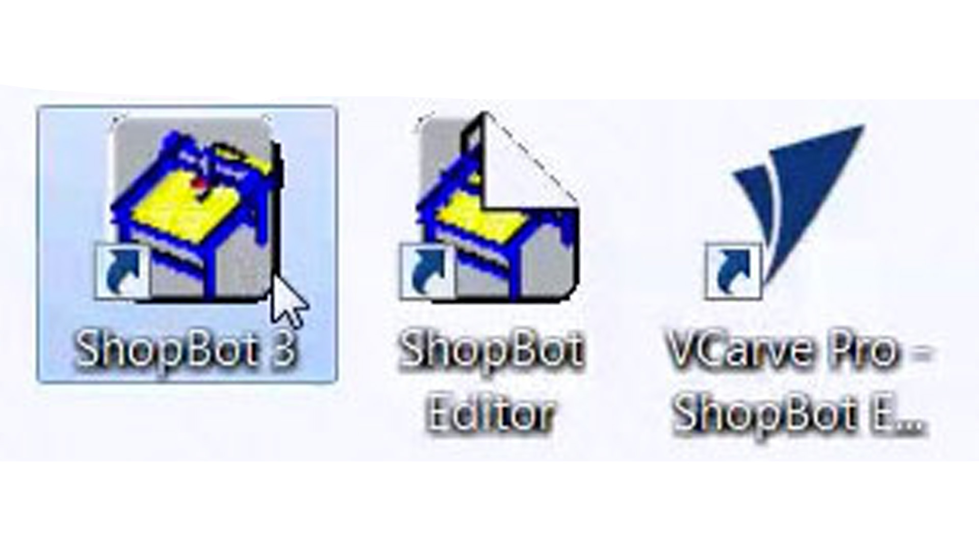
To set up the file to be sent to the CNC machine, we used the ShopBot's software which is the Vcarve Pro. With this program, you can open your DXF file and set how it will be cut.
I have read and learn more about the following Quick Start Guide to get the job done this week and use the machine correctly
This panel contains many of the main elements to control the machine. Through this panel, it can show the Keybad panel, which can be reset by re-zeroing the axes and adjusting the blade as required. The Keybad can be shown through the yellow mark in the image below.
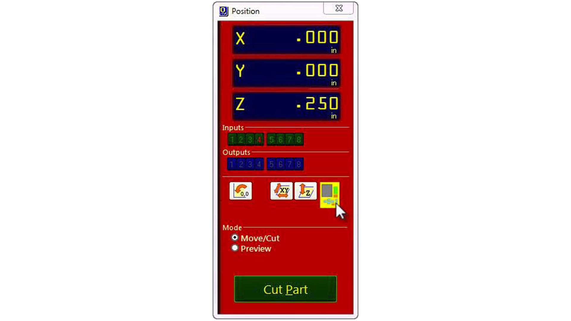
To control the machine and calibrate it, we used a software called ShopBot 3. Using this software, you can set the zeros for the x,y and z axes. To chose the zero for the x & y, you move the arrows till the spindle is right where you want it and you zero it there.
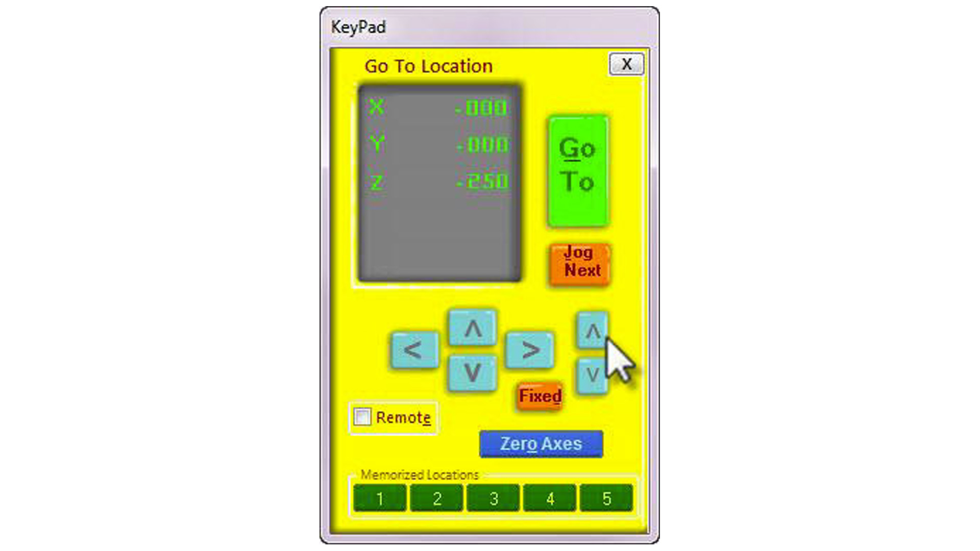
For the z-axis, you press to zero the z, but only before placing the clip on the spindle and the matal plate under the spindle, the machine calibrates the z automatically by slowly lowering the spindle till a short circuit occurs.
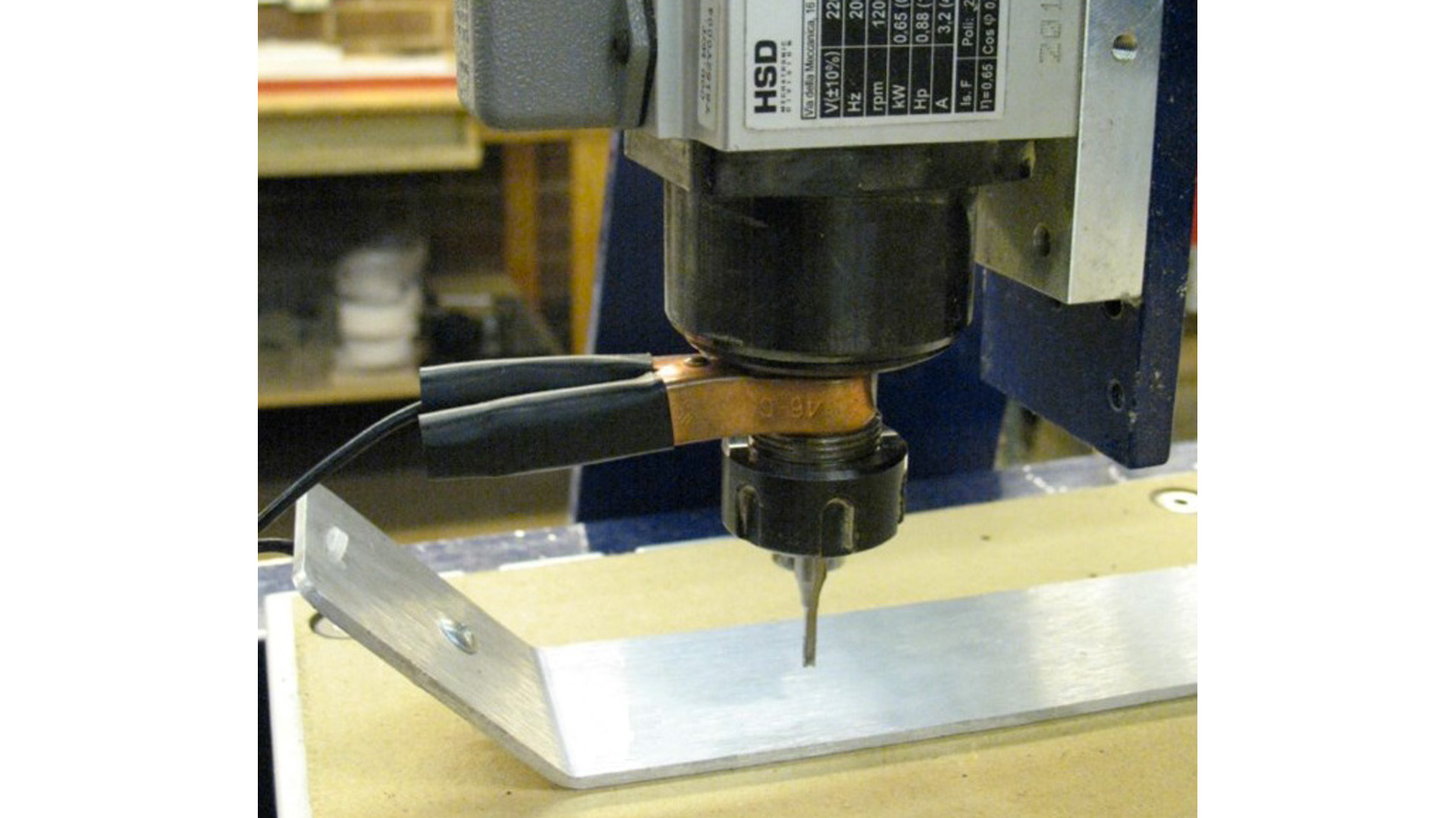
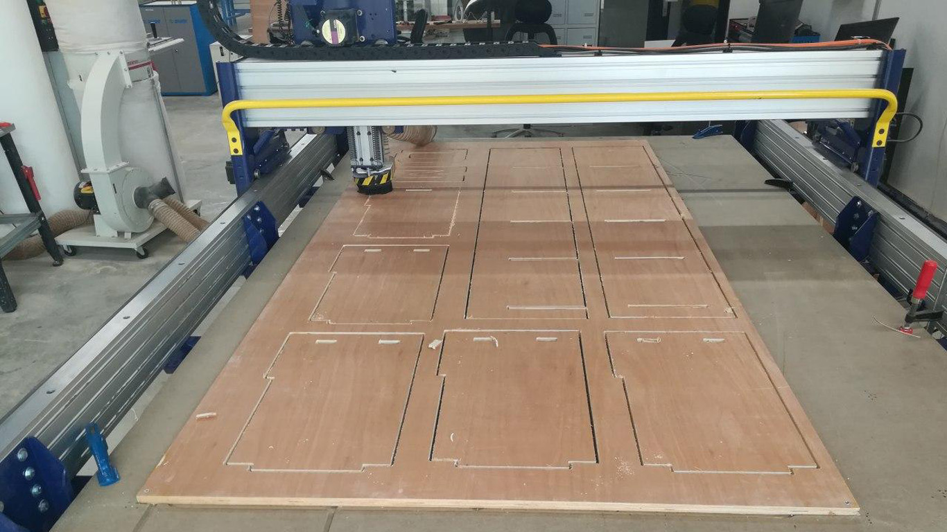
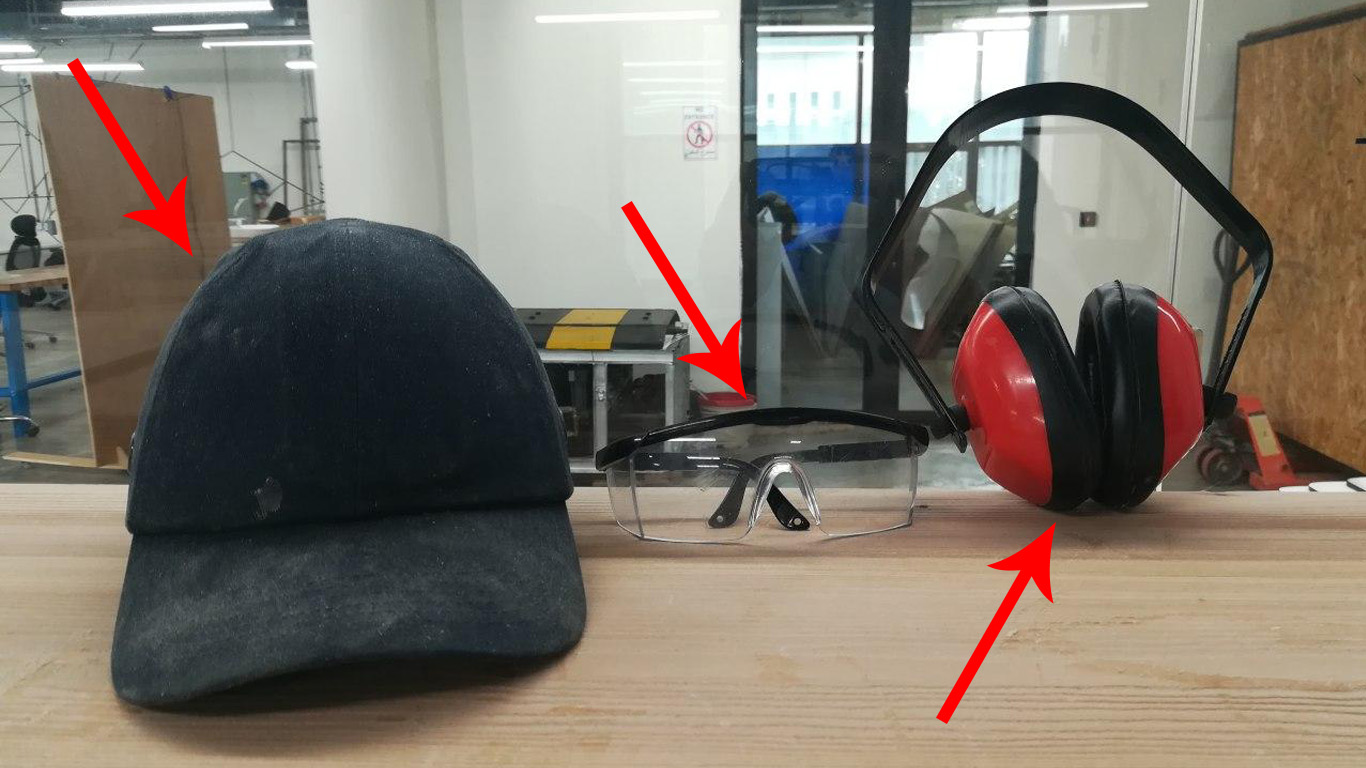
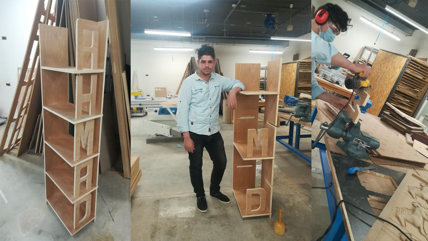
In the following pictures the machine appears to be cutting, I used PlyWood wood at a height of "18mm". I took about "50 Min" time, during the cutting process I needed to adhere to the general safety rules where I have to wear headphones to avoid disturbing sound - Wearing glasses for fear of blowing wood scattered especially on the face and eyes - wearing the hat to avoid the dust that results from the wood during cutting or smoothing the edges after the machine has finished cutting - also the muzzle must be worn for fear of wood dust entering the mouth - it is preferable to wear Labcot also, prevents entry to Inside the designated yellow line where it can cause trouble L It is a very dangerous movement.
Files - Open Source
Group Assignment