Output Devices
This week, I did a trial run on my electronic board that I designed and manufactured for the final project, I used in the testing process these sensors and motors as it is the main subject of my final project, so I will use the motor and move it based on the movement of the person that the sensors will pick up.
What is Output Devices?
First let's get to know the output devices and what they involve، Output devices can be expressed by its name. When looking at the name, the word output appears in the mind, meaning that these devices are based on the output and show what has been programmed on it، That is, it is the output that the user outputs the data processingTypes of output devices:
Schematic and Board
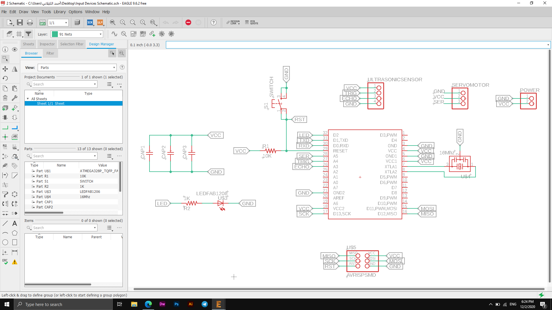
I used Atmega328p in my board for Output Devices week as it can do the job of Arduino, and I also needed to add ports for the sensor and the motor as the image below shows the labels for each of them.
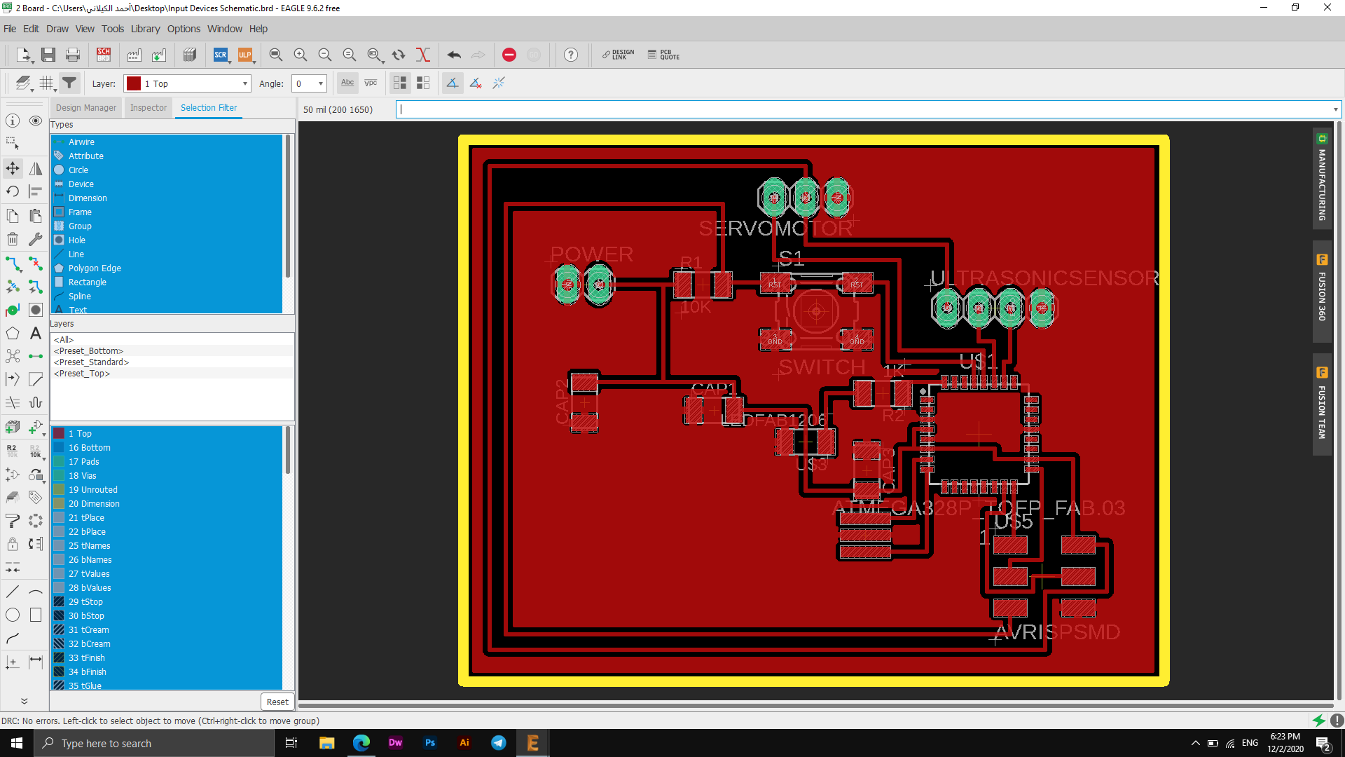
I have not encountered any problems in terms of the connections as shown in the picture above in the lower corner that there are no errors in the process of connecting the electronic board.
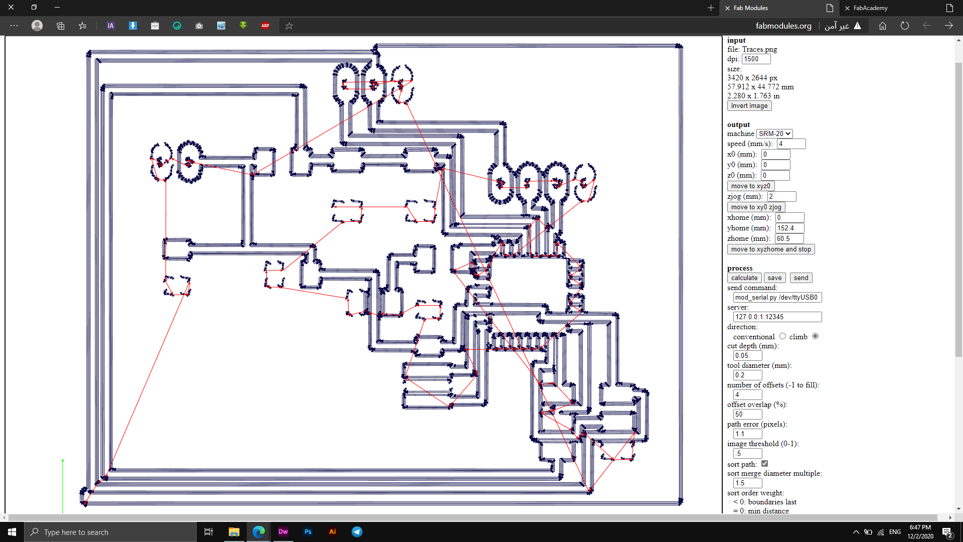
Next, I imported the board displaying only the top layer and the pads as an monochrome image and used Fabmodules to set the settings of milling as seen below.
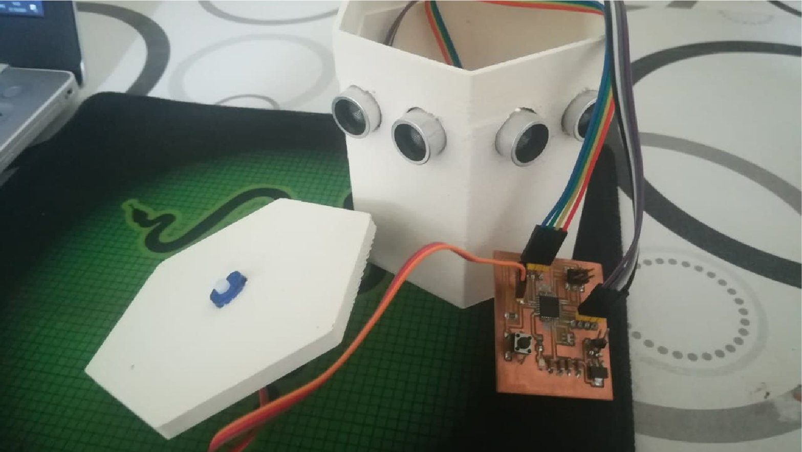
This week I did a test to test the Output devices, I am supposed to use the electronic board that I designed two weeks ago but due to the conditions and quarantine on the country I live in and the laboratory closed I could not reach my Board, so I used some components as LEDs - Resistors - Ponometer - Wires - Arduino Uno - Software Arduino.
The operation was performed on an ultrasonic sensor device, where this device senses the movement and moves the engine in the direction that the sensor captures, as it will act as an Output device that receives the sensors of people and their bodies and gives commands according to them.
Component Used
After I made the connection process, which is shown in the following image, it is time to program the electronic board to do the action of my choice. I prepared the code and at the bottom the explanation of the code and what it indicates, continue below.
Arduino Code
Servo myservo; Creates Servo Object
Test with My Board
Files - Open Source
Arduino CodeOUTPUT Devices
This week I built an experiment that works with the output devices and programmed it through Arduino software so that it gives a specific output that is determined at the end of the process and run the experiment, I was supposed to do this experiment on my tablet that was designed in Elctronics Design week but as a result of not Our ability to reach the laboratory so I had to do an experiment with some of the pieces I had.
What is OUTPUT Devices?
First let's get to know the output devices and what they involve، Output devices can be expressed by its name. When looking at the name, the word output appears in the mind, meaning that these devices are based on the output and show what has been programmed on it، That is, it is the output that the user outputs the data processing
Types of output devices:
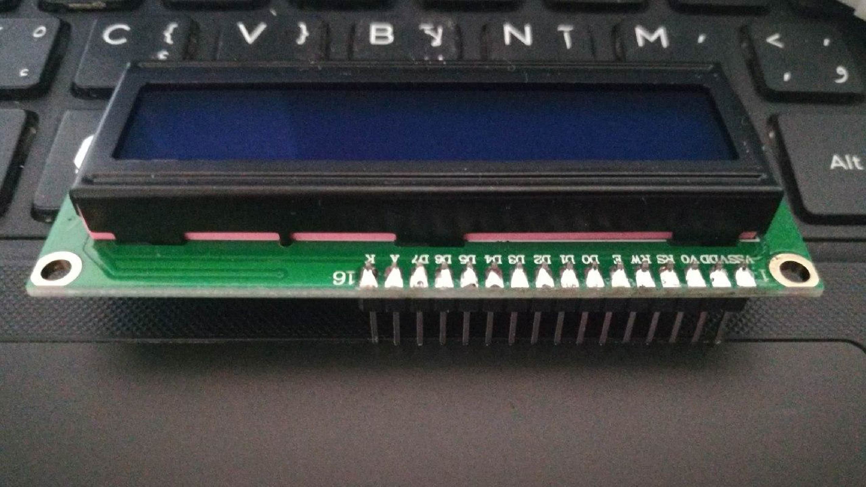
In this experiment, I used the "LCD" screen and programmed it to display the words you specified in the code assigned to this process.
Component Used
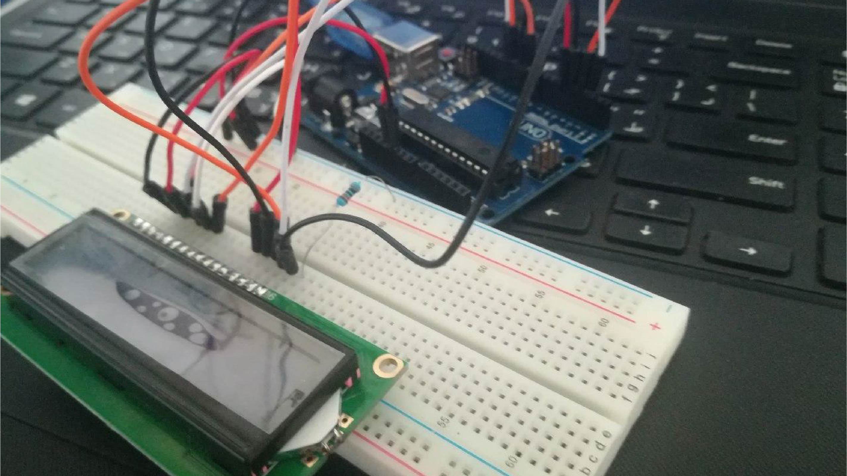
I performed my experiment first without soldering the "LCD" ports to the pins that would be connected with Breadboard and I had a problem that the screen ports are wide enough and a permanent connection cannot be established through it so I had to weld it and then the experiment started.
To connect the wires correctly, the following diagram shows the ports on which the wiring was connected to work properly.
Connection scheme
After completing the connection process I proceeded to write the Arduino code that will launch the screen and display the content. First you must include the "LiquidCrystal" library that will recognize the screen and then write the code. The following image shows the process of including the library.

I have written my code which I will use as it shows many values including the screen playback time and display name of "6000" milliseconds, also the text that will be displayed on the screen in addition to some other values that appear in the blinking time and the time to turn off the screen light and the duration of its operation.
The following video explains the process:
ؤ