WEEK 9 - Mechanical Design
☑ Work and communicate effectively in a team and independently.
☑ Design, plan and build a system.
☑ Analyse and solve technical problems.
☑ Recognise opportunities for improvements in the design.
☑ Include design files and a ‘hero shot’
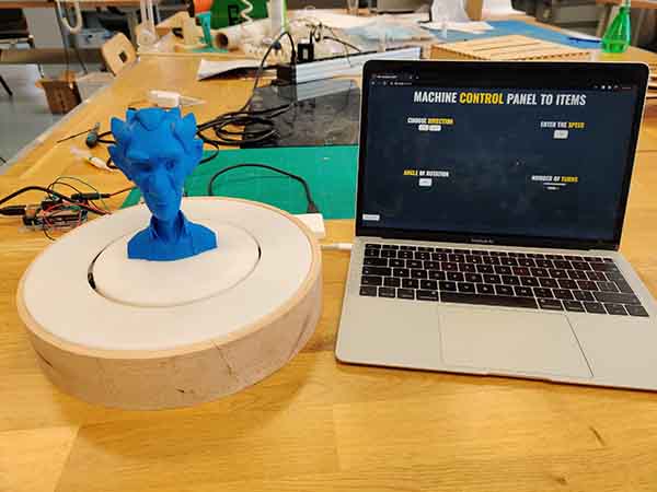
Automated Turntable
In this week machine building assignment Ranjit, Kitja and I decided to build an Automated Turntable that can be used for capturing 360 Product Photos.
Ranjit worked on the Electronics, Grbl and power supply where Kitja worked on the Owesome Python Interface.
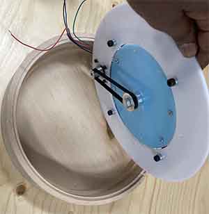
Automated Turntable setup
|
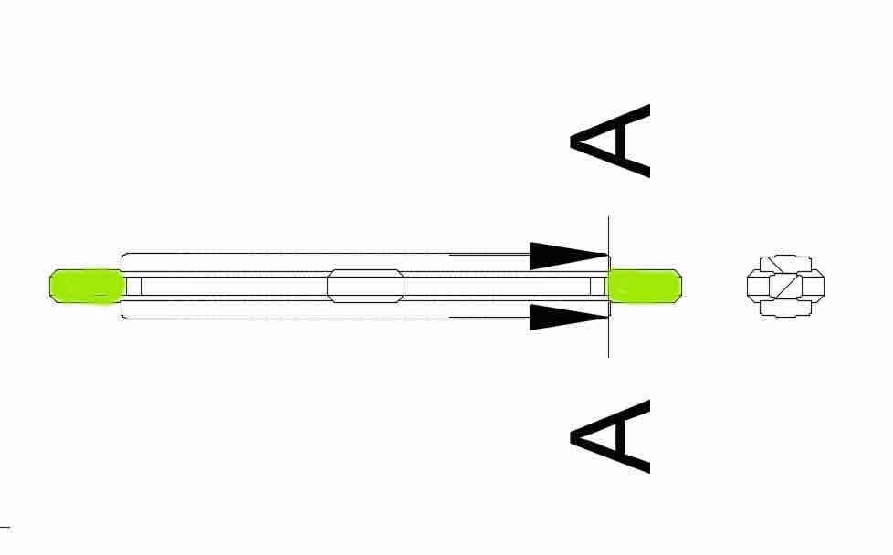
Mechanical designDesign a 3D model of the Whole assemblyMy part of this assignment was to design and fabricate the mechanical structure of the machine. The the turn table assembly system consites of different components. We used Laser Cutter, CNC Machine and 3D Printing to manufacture the parts. The material I used was mainly PMMA for the laser cut plates, the circular V Slot for the rotary table was 3D printed using PLA filament. We decided to a Nema 17 Motor with 2 gears and a timing belt transmission. The bigger gear was attached to the bottom part of the Circular V Slot , which was then connected to the Stepper motor that is mounted to the support surface Plate via a timing Belt. I decided to use Fusion 360 to create the mechanical assembly and later the components where exported as Dxf File for laser cutting or as Stl for 3d Printing. Designing with Fusion 360I did this assignment design using Fusion 360. The machine will have 12 different components. I looked into how others have approched the design of such turn table in general and found out they mostly use some kind of prexisting rotary based assembly and add the activation part. I Would like to take a different approch and design a Circular V slot and Bearing assembly to recreat the same smooth turning capability as the comercial alternative. At this point of documenting the project I could say creating a perfectly aligned smooth movement has been a challenge as the main part was manufactured using FDM 3d printers and with a lot of support material that has to be cleaned after which affects the Smoothness and creat a bit of friction on the bearings and adding extra load on the Stepper motor. Next I will explain step by step the modelling process: The circular V-Slot
The most important part of the design as this part needs to be stable and frictionless for the whole machine to perform.
The idea is to have have 4 Bearings used as a guide to make the V slot rotate freely.
I copied the Bearing I desided to use using rectangular pattern copy and determine the Cross section for the V-Slot (Sketch >
Slots > Center to Center Slot)
The sketch used for getting the profile of rotating V Slot.
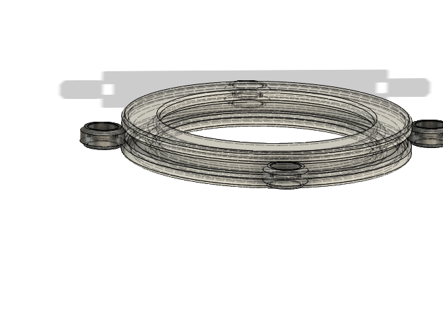
Figure 5. Using the Revolve the profile sketch used for revolving tool to Created the rotating.
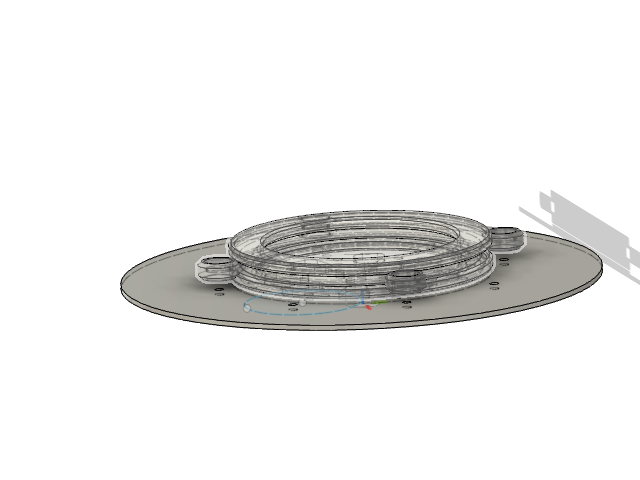
Figure 6. Extruding the sketch to create the
Plate for Motor Mount. Extruding distance parametric
(material thickness)
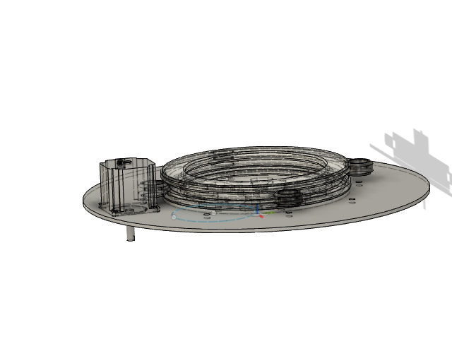
Figure 7. I then used inserted a nema 17 Stepper motor from the mcmaster library
utilized the insert > move
We need to consider how we will mount the timing belt and control the tension on the belt. So I created a groove on where the M3 Bolts will be used to mount the stepper Motor. .Smaller GearAfter calculating the gear ratio needed insert and timing belt Gear joint. 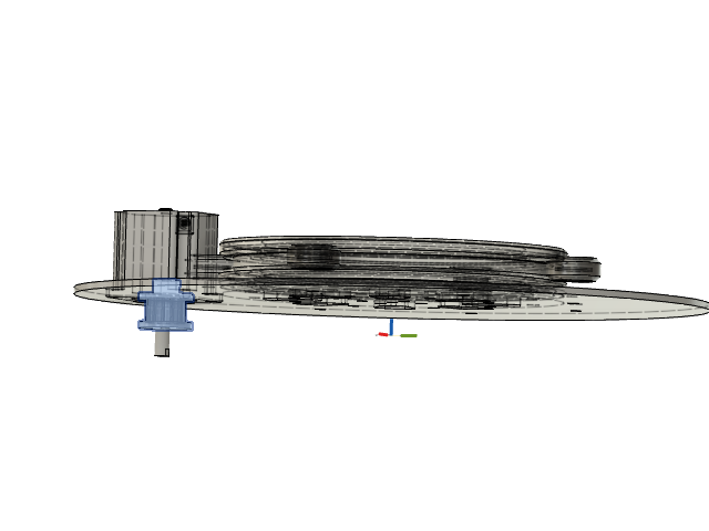
Figure 8. I then used insert timing belt gear from the mcmaster library
utilized the insert > move
.
Larger Gear
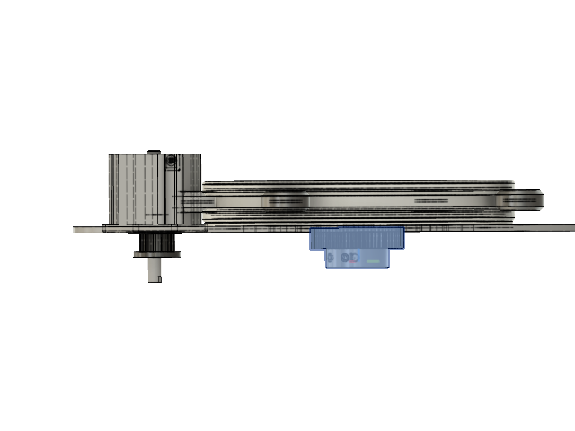
Figure 9. I then used insert timing belt Gear from the mcmaster library
utilized the insert > move
Timing BeltI created a scetch around the Small gear all the way to the Large gear 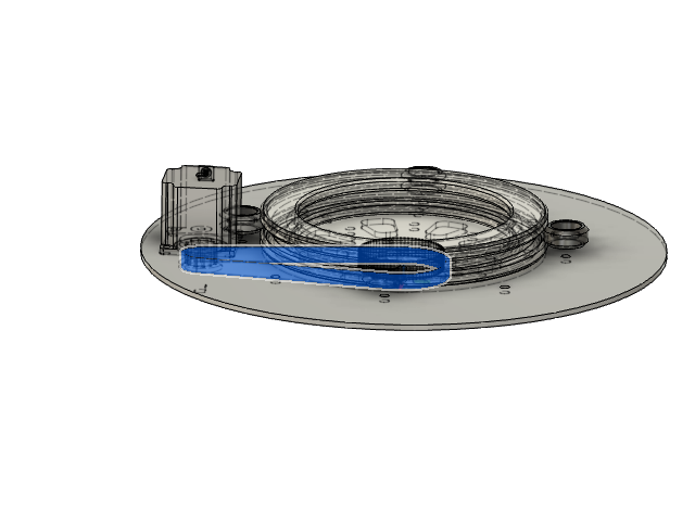
Figure 10. I then used insert timing belt Gear from the mcmaster library
utilized the Sketch > offset and Extrude
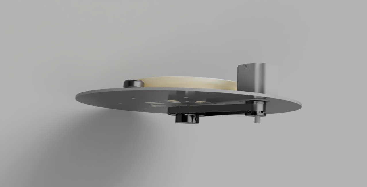
Figure 11. Here is the Rendering
OVERVIEWBuilding your own Spin system involves fabricating the mechanical turntable, assembling the Arduino grbl shield, and 3D printing a motor gears. All purchased parts are available online from McMaster, Digikey, Sparkfun, and Amazon. The raw materials cost around €100. There are quick links to most materials on the left; these links exclude any acrylic or fasteners you'll need to fabricate and assemble the turntable. The following tools are necessary for assembling your Spin turntable You will also need to use the following machines:
The turntable consists of laser cut, 3D printed, and purchased parts. Recommended parts are listed below. It is highly recommended that you purchase the fasteners at your local hardware store since the parts are only available in bulk online. You can find direct links to Sparkfun, McMaster, and Digikey carts on the left side of this page. Alternatively, if you want me to mail you a kit of fasteners, send me an email at spinturntable (at) gmail (dot) com.
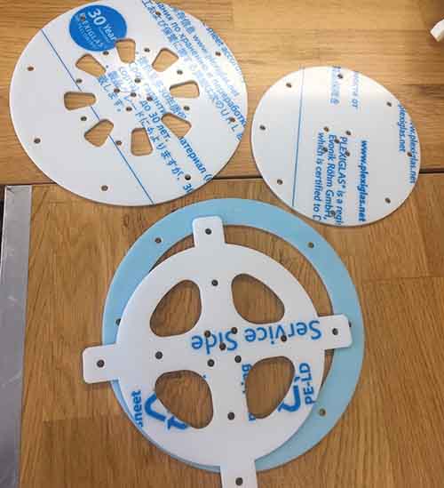
TURNTABLE FABRICATIONLaser CuttingSpin consists of 3mm-thick clear acrylic parts however as the design is parametric one can use any thickness. However as this thickness will have an effect to the gab between the plates and the rotating V slot, on has to change the spacer dimensions.
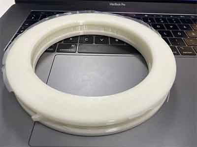
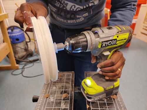
First, laser cut the base, outer gear, and stepper motor case parts out of the 3/16” acrylic (all vector cuts): 3D Printing3D print the V-Slot Circular rotary part [stl].
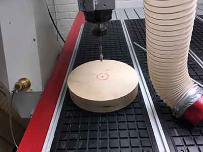
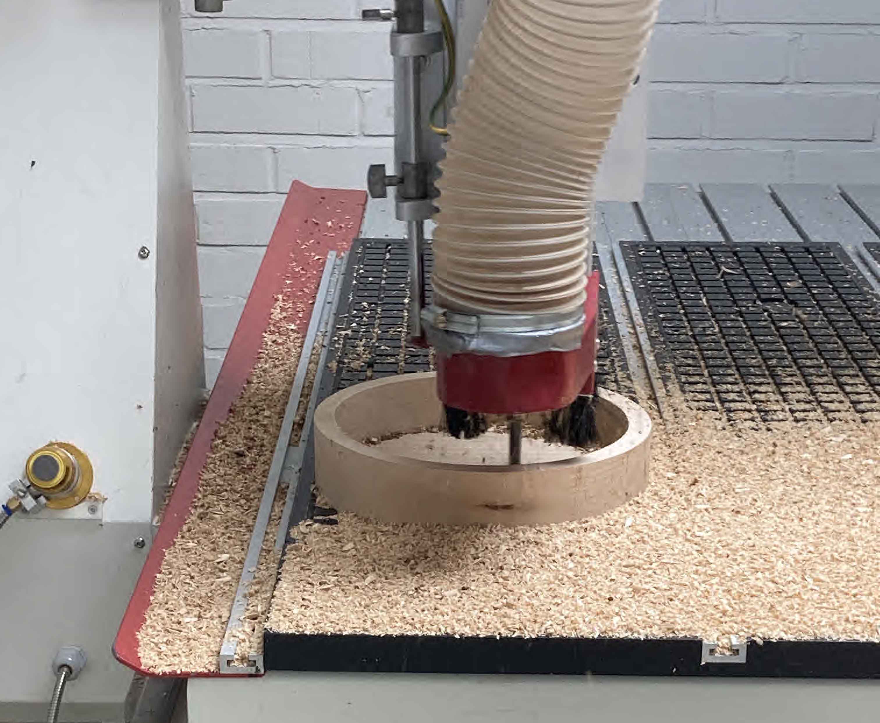
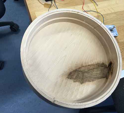
NOTE: I highly recommend printing the motor gear in ABS and not PLA, which is more susceptible to warping and heat damage. CNC machining the base
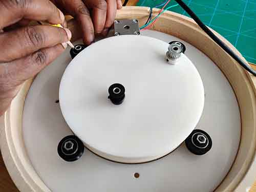
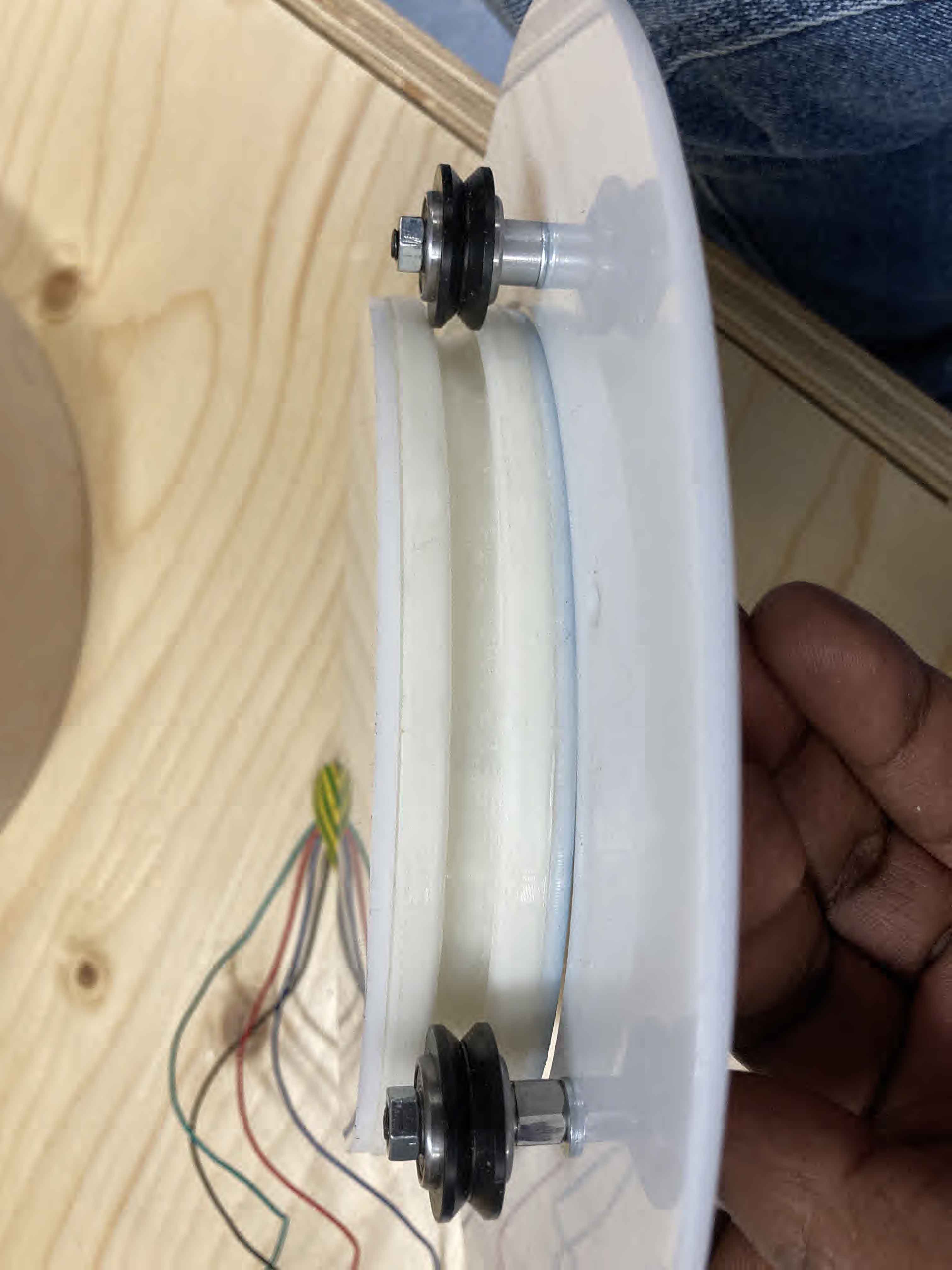
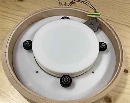
AssemblyFirst, Connect the 3 bearings with the M5 nuts and the Spacer but don't tighten the screws yet. Then insert the Circular V slot then add the 4th Bearing and the nuts with the spacer make sure the allignment is straight and tigten the nuts
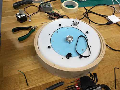
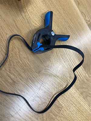
Measure the needed length of the timing belt, cut and glue the ends using epoxy to make a continuous belt
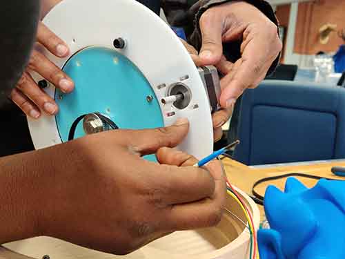
Now that we have all the needed parts in place, Mount the Motor and the Small gear on the Shaft and the Big motor on the base of the rotating V-slot and insert the Timing belt
Issues I foundThe glued Timing belt didn't worked as smoothly as it would using a continuous pre-made Belt which demanded a bit more torque from our motor. We reduced the friction my trining out some edges from the connection area. The 3d Printed v slot had some supports and after removing them the surface was not smooth enough in the start so a lot of sanding had to be made to reduce the friction on the Bearings.
Link to this weeks group assignment with Kitja and Ranjit : Group assignment Files
TURN TABLE FUSION FILE -
TURN TABLE ASSEMBLY
|