EXAMPLES FOLLOWED
This week I started by having a good look at some examples:
I was interested in understanding the differences between this projects in the context of code, components and use.
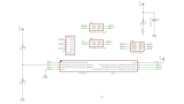
NEIL'S STEP RESPONSE & DAN'S STEP RESPONSE boards both use ATTINY45 with Pinouts as follows:
PB5
PB3 (shield/step/charge pin)
PB4 (sense pin)
GND
VCC
PB2 > receive pin rx
PB1
PB0
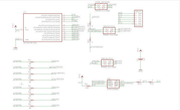
AKASH AND MATT'S STEP RESPONSE uses:
ATTINY44 based Board with Pinouts as follows:
VCC
PB0
PB1> chargeport rx
PB3
PB2> charge pin
PA7> sense7
PA6> sense6
GND
PA0> sense0
PA1> sense1
PA2> sense2
PA3> sense3
PA4> sense4
PA5> sense5
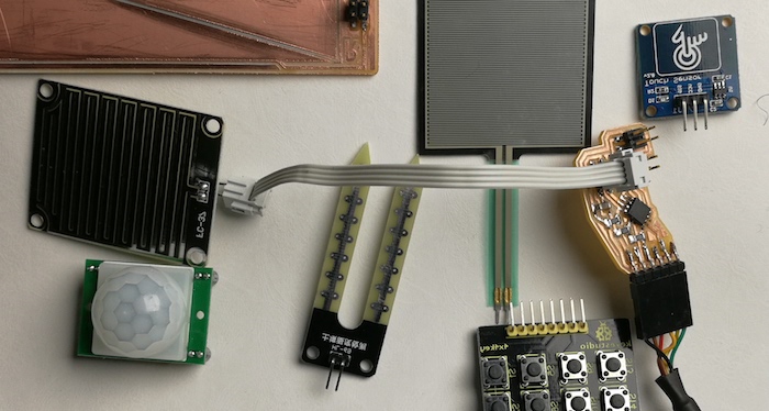
All board work by sensing a change in capacitance, allowing to record touch interactions on the surface. Akash and Matt are using a ATTINY44, whereas Neil's step/response example uses ATTINY45. Their boards multiply the amount of pins used as sense pins, but still use one singe step/charge pin as in Neil's example. The code is of course more complex, but for now I am trying to understand the hardware. Since reading Dan's documentation I found out that he had problems in making Akash's and Matt's boards working I decided to get started from Neil's transmit-receive example.
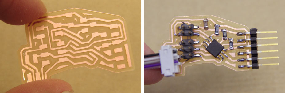
Design-wise I decided to make my boards in a way that they will be able to connect to a variety of capactive sensing substrates, in a variety of shapes and materials; so instead of integrating the sensing pads on the programmed board itself, I made a separate txrx pcb board connected via headers. This way I can interchange this with others, test flexible plastic and textile bases, copper traces, conductive paint traces, embroidered traces etc... So both boards use 2x2 header pins
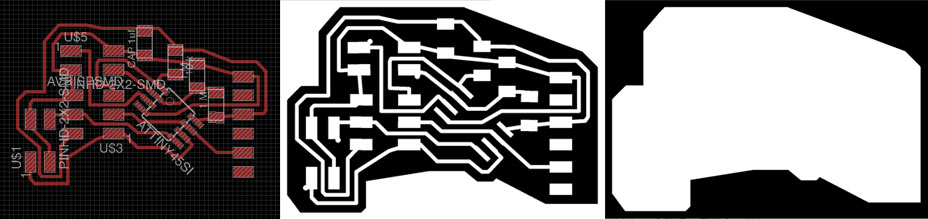
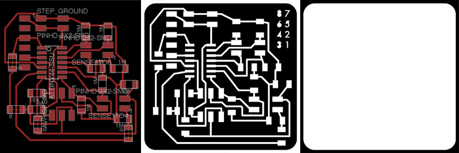
So I designed and milled 3 pcb boards:
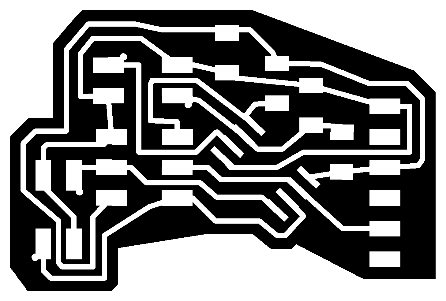
- RXTX Board :Neil's transmit/receive board (with an additional 2x2 pin header reusing some pins after programming)
- RXTX PAD: transmit receive pcb board unit
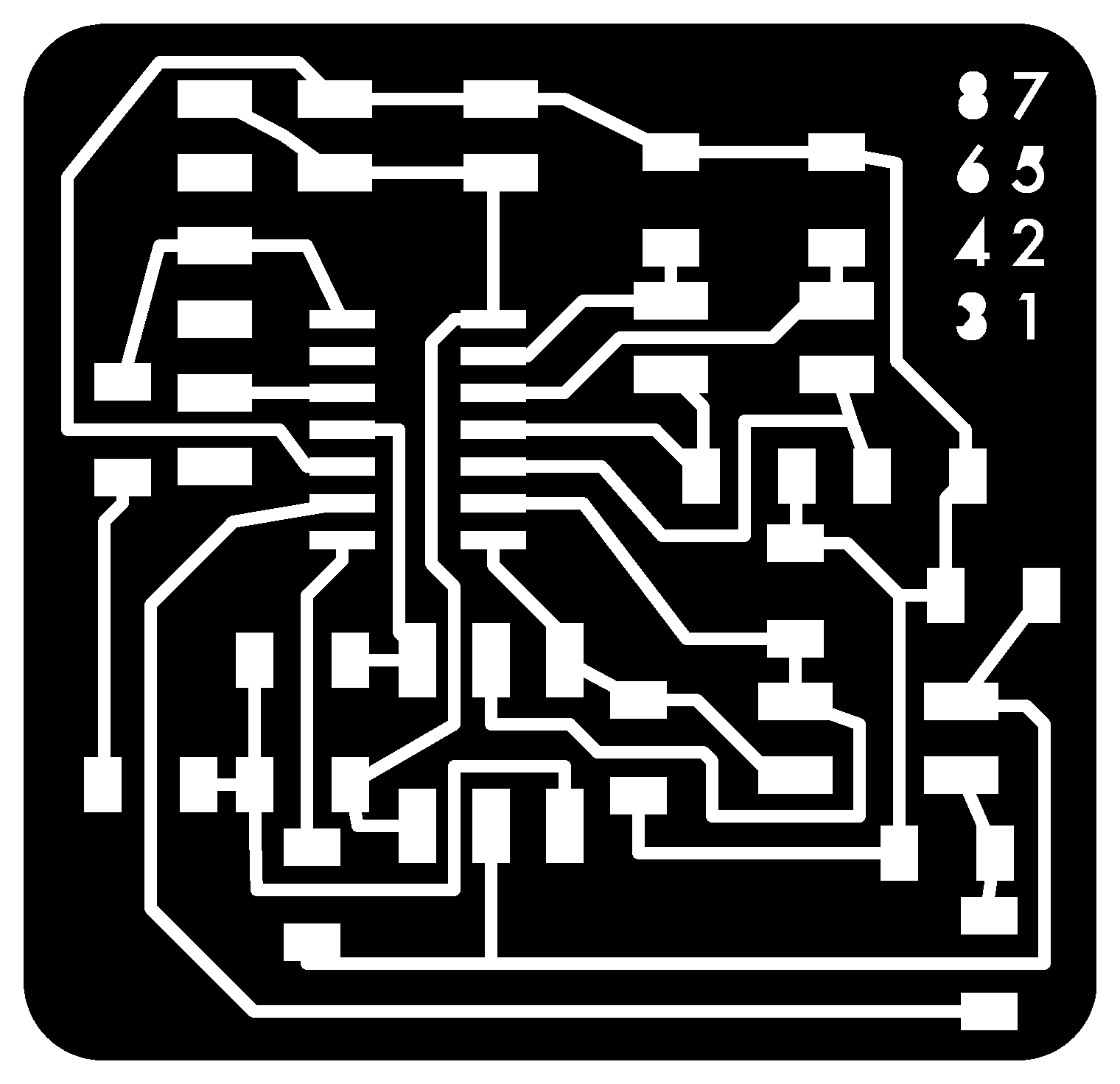
- 8 PINS STEP/RESP: Matt's 8 pins step response board redesigned.
RXTX board:
COMPONENTS USED:
RXTX PAD:
8 PINS STEP/RESP:
MILLED BOARDS
Traces width: 0.4064
PNG file border: 0.8 mm

REFRESHING MY MODELA MILLING SKLLS
1.
Never change mill bit when in view (light on if I'm in view) because it means that the machine is still in the middle of a previous process and you'll risk to damage the mill by moving to xy position and actually also stepping down in the z , since Z is always remembered from the latest ran file!
2.
To delete a running program on the Modela in Linux:
- open new tab on terminal and type:
ps -e | grep cat
- a list like this will appear:
2098? 00:00:00 cat
- kill cat:
kill 2098
'Cat' are all the processes that communicate through serial port with the computer. We are sending data from and to the Modela so we need to find the serial cat and shut it down.
Then press Z up and down at the same time on the machine, there will be a light flashing, when it stops blinking it is successfully reset!
3.
'VIEW' is the back right corner.
If we leave view by pressing it again and no process is still running, the machine should go to the front left corner. From here, I can change my mill bit and move to my new xy position.
I first downloaded the hello.load.45.c Neil's code and modified the pin setup definition according to my schematics.
hello.load.45.c Code
// // hello.load.45.c // // step response loading hello-world // 9600 baud FTDI interface // // Neil Gershenfeld // 10/27/10 // // (c) Massachusetts Institute of Technology 2010 // This work may be reproduced, modified, distributed, // performed, and displayed for any purpose. Copyright is // retained and must be preserved. The work is provided // as is; no warranty is provided, and users accept all // liability. // #include#include #define output(directions,pin) (directions |= pin) // set port direction for output #define set(port,pin) (port |= pin) // set port pin #define clear(port,pin) (port &= (~pin)) // clear port pin #define pin_test(pins,pin) (pins & pin) // test for port pin #define bit_test(byte,bit) (byte & (1 << bit)) // test for bit set #define bit_delay_time 102 // bit delay for 9600 with overhead #define bit_delay() _delay_us(bit_delay_time) // RS232 bit delay #define half_bit_delay() _delay_us(bit_delay_time/2) // RS232 half bit delay #define charge_delay_1() _delay_us(1) // charge delay 1 #define charge_delay_2() _delay_us(10) // charge delay 2 #define charge_delay_3() _delay_us(100) // charge delay 3 #define settle_delay() _delay_us(100) // settle delay #define char_delay() _delay_ms(10) // char delay #define serial_port PORTA #define serial_direction DDRA #define serial_pin_out (1 << PA1) #define charge_port PORTA #define charge_direction DDRA #define charge_pin (1 << PA3) void put_char(volatile unsigned char *port, unsigned char pin, char txchar) { // // send character in txchar on port pin // assumes line driver (inverts bits) // // start bit // clear(*port,pin); bit_delay(); // // unrolled loop to write data bits // if bit_test(txchar,0) set(*port,pin); else clear(*port,pin); bit_delay(); if bit_test(txchar,1) set(*port,pin); else clear(*port,pin); bit_delay(); if bit_test(txchar,2) set(*port,pin); else clear(*port,pin); bit_delay(); if bit_test(txchar,3) set(*port,pin); else clear(*port,pin); bit_delay(); if bit_test(txchar,4) set(*port,pin); else clear(*port,pin); bit_delay(); if bit_test(txchar,5) set(*port,pin); else clear(*port,pin); bit_delay(); if bit_test(txchar,6) set(*port,pin); else clear(*port,pin); bit_delay(); if bit_test(txchar,7) set(*port,pin); else clear(*port,pin); bit_delay(); // // stop bit // set(*port,pin); bit_delay(); // // char delay // bit_delay(); } int main(void) { // // main // static unsigned char up_lo,up_hi,down_lo,down_hi; // // set clock divider to /1 // CLKPR = (1 << CLKPCE); CLKPR = (0 << CLKPS3) | (0 << CLKPS2) | (0 << CLKPS1) | (0 << CLKPS0); // // initialize output pins // set(serial_port, serial_pin_out); output(serial_direction, serial_pin_out); clear(charge_port, charge_pin); output(charge_direction, charge_pin); // // init A/D // ADMUX = (0 << REFS1) | (0 << REFS0) // Vcc ref | (0 << ADLAR) // right adjust | (0 << MUX4) | (0 << MUX3) | (0 << MUX2) | (1 << MUX1) | (0 << MUX0); // PA2 ADCSRA = (1 << ADEN) // enable | (1 << ADPS2) | (1 << ADPS1) | (1 << ADPS0); // prescaler /128 // // main loop // while (1) { // // send framing // put_char(&serial_port, serial_pin_out, 1); char_delay(); put_char(&serial_port, serial_pin_out, 2); char_delay(); put_char(&serial_port, serial_pin_out, 3); char_delay(); put_char(&serial_port, serial_pin_out, 4); // // settle, charge, and wait 1 // settle_delay(); set(charge_port, charge_pin); charge_delay_1(); // // initiate conversion // ADCSRA |= (1 << ADSC); // // wait for completion // while (ADCSRA & (1 << ADSC)){ // niente } // // save result // up_lo = ADCL; up_hi = ADCH; // // settle, discharge, and wait 1 // settle_delay(); clear(charge_port, charge_pin); charge_delay_1(); // // initiate conversion // ADCSRA |= (1 << ADSC); // // wait for completion // while (ADCSRA & (1 << ADSC)) ; // // save result // down_lo = ADCL; down_hi = ADCH; // // send result // put_char(&serial_port, serial_pin_out, up_lo); char_delay(); put_char(&serial_port, serial_pin_out, up_hi); char_delay(); put_char(&serial_port, serial_pin_out, down_lo); char_delay(); put_char(&serial_port, serial_pin_out, down_hi); char_delay(); // // settle, charge, and wait 2 // settle_delay(); set(charge_port, charge_pin); charge_delay_2(); // // initiate conversion // ADCSRA |= (1 << ADSC); // // wait for completion // while (ADCSRA & (1 << ADSC)) ; // // save result // up_lo = ADCL; up_hi = ADCH; // // settle, discharge, and wait 2 // settle_delay(); clear(charge_port, charge_pin); charge_delay_2(); // // initiate conversion // ADCSRA |= (1 << ADSC); // // wait for completion // while (ADCSRA & (1 << ADSC)) ; // // save result // down_lo = ADCL; down_hi = ADCH; // // send result // put_char(&serial_port, serial_pin_out, up_lo); char_delay(); put_char(&serial_port, serial_pin_out, up_hi); char_delay(); put_char(&serial_port, serial_pin_out, down_lo); char_delay(); put_char(&serial_port, serial_pin_out, down_hi); char_delay(); // // settle, charge, and wait 3 // settle_delay(); set(charge_port, charge_pin); charge_delay_3(); // // initiate conversion // ADCSRA |= (1 << ADSC); // // wait for completion // while (ADCSRA & (1 << ADSC)) ; // // save result // up_lo = ADCL; up_hi = ADCH; // // settle, discharge, and wait 3 // settle_delay(); clear(charge_port, charge_pin); charge_delay_3(); // // initiate conversion // ADCSRA |= (1 << ADSC); // // wait for completion // while (ADCSRA & (1 << ADSC)) ; // // save result // down_lo = ADCL; down_hi = ADCH; // // send result // put_char(&serial_port, serial_pin_out, up_lo); char_delay(); put_char(&serial_port, serial_pin_out, up_hi); char_delay(); put_char(&serial_port, serial_pin_out, down_lo); char_delay(); put_char(&serial_port, serial_pin_out, down_hi); char_delay(); } }
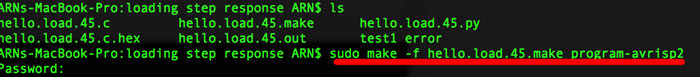
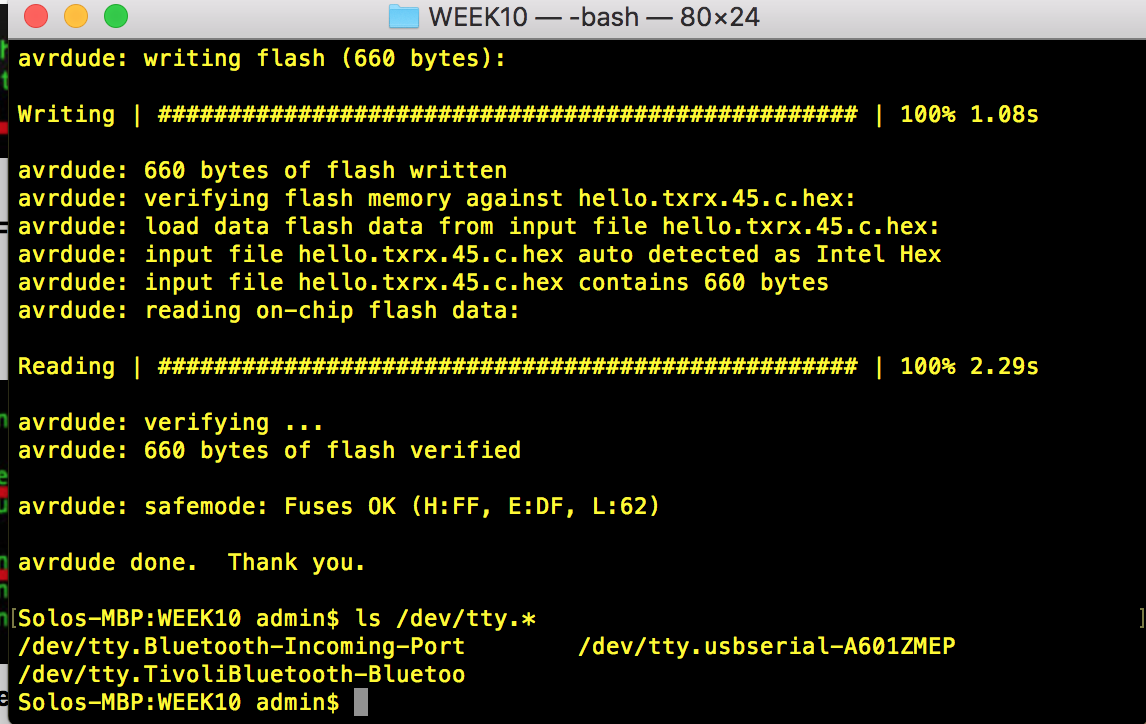
Then I created the makefile and run in terminal avr dude commands.
    make -f hello.load.45.make
    make -f hello.load.45.make program_usbtiny_fuses
    make -f hello.load.45.make program_usbtiny
PYTHON 3.4.3
I needed to install python tkinter. Here depending on the version of python you are using, you need tkinter or Tkinter.
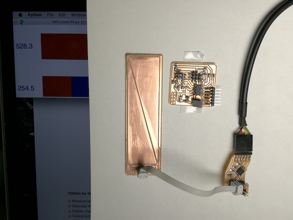
As final step, to receive and display loading step response.
I used a pythone code from Neil for tkinter called hello.light.45.py and try to understand the code and what it does to creat the graphical interface i have added my comment on the below code to follow what Neil is trying to do.
#
# hello.light.45.py
#
# receive and display light level
# hello.light.45.py serial_port
#
# Neil Gershenfeld
# CBA MIT 10/24/09
#
# (c) Massachusetts Institute of Technology 2009
# Permission granted for experimental and personal use;
# license for commercial sale available from MIT
#
# Modified 4/13 by Embafrash Solomon to read Step responce sensor
from Tkinter import *
import serial

WINDOW = 600 # window size
eps = 0.5 # filter time constant
filter = 0.0 # filtered value

def idle(parent,canvas):
   global filter, eps # global variables
   #
   # idle routine
   #
   byte2 = 0
   byte3 = 0
   byte4 = 0
   ser.flush()
   while 1:
      #
      # find framing
      #
      byte1 = byte2
      byte2 = byte3
      byte3 = byte4
      byte4 = ord(ser.read())
      if ((byte1 == 1) & (byte2 == 2) & (byte3 == 3) & (byte4 == 4)):
         break
   low = ord(ser.read())
   high = ord(ser.read())
   value = 256*high + low
   filter = (1-eps)*filter + eps*value
   x = int(.1*WINDOW + (.9-.1)*WINDOW*filter/1024.0)
   canvas.itemconfigure("text",text="%.1f"%filter)
#
# moves arrow polygon to match input
#
   canvas.coords('marker',.31*WINDOW,x,.42*WINDOW,x+.03*WINDOW,.42*WINDOW,x+.05*WINDOW,.45*WINDOW,x+.05*WINDOW,.45*WINDOW,x+.03*WINDOW,.46*WINDOW,x+.01*WINDOW,.46*WINDOW,x-.01*WINDOW,.45*WINDOW,x-.03*WINDOW,.45*WINDOW,x-.05*WINDOW,.42*WINDOW,x-.05*WINDOW,.42*WINDOW,x-.03*WINDOW)
   canvas.update()
   parent.after_idle(idle,parent,canvas)

#
#  check command line arguments
#
if (len(sys.argv) != 2):
   print "command line: hello.light.45.py serial_port"
   sys.exit()
port = sys.argv[1]
#
# open serial port
#
ser = serial.Serial(port,9600)
ser.setDTR()
#
# set up GUI
#
root = Tk()
#
# sets the text that appears in the title bar
#
root.title('Light Level -- hello.stepresponce.45.py (q to exit)')
#
# sets the letter q on the keyboard to trigger exiting the script
#
root.bind('q','exit')
#
# creates the blank window
#
canvas = Canvas(root, width=.5*WINDOW, height=WINDOW, background='black')
#
# sets the font and size of the type used for the number readings and label
# the next text line can be commented out for a more accurate appearance
#
canvas.create_text(.15*WINDOW,.075*WINDOW,text=".33",font=("Helvetica", 20),tags="text",fill="yellow")
canvas.create_text(.15*WINDOW,.95*WINDOW,text="LIGHT",font=("Helvetica", 20),tags="label",fill="yellow")
#
# creates scale
#
canvas.create_rectangle(.15*WINDOW,.1*WINDOW,.16*WINDOW,.26*WINDOW, tags="scale1", fill='red')
canvas.create_line(.12*WINDOW,.1*WINDOW,.19*WINDOW,.1*WINDOW,fill='red')
canvas.create_text(.10*WINDOW,.1*WINDOW,text="0",font=("Helvetica", 10),fill="red")
canvas.create_line(.14*WINDOW,.18*WINDOW,.17*WINDOW,.18*WINDOW,fill='red')
canvas.create_line(.12*WINDOW,.26*WINDOW,.19*WINDOW,.26*WINDOW,fill='red')
canvas.create_text(.10*WINDOW,.26*WINDOW,text="200",font=("Helvetica", 10),fill="red")
canvas.create_line(.14*WINDOW,.33*WINDOW,.17*WINDOW,.33*WINDOW,fill='yellow')
canvas.create_line(.12*WINDOW,.41*WINDOW,.19*WINDOW,.41*WINDOW,fill='yellow')
canvas.create_text(.10*WINDOW,.41*WINDOW,text="400",font=("Helvetica", 10),fill="yellow")
canvas.create_rectangle(.15*WINDOW,.26*WINDOW,.16*WINDOW,.49*WINDOW, tags="scale2", fill='yellow')
canvas.create_line(.14*WINDOW,.49*WINDOW,.17*WINDOW,.49*WINDOW,fill='green')
canvas.create_line(.12*WINDOW,.57*WINDOW,.19*WINDOW,.57*WINDOW,fill='green')
canvas.create_text(.10*WINDOW,.57*WINDOW,text="600",font=("Helvetica", 10),fill="green")
canvas.create_rectangle(.15*WINDOW,.49*WINDOW,.16*WINDOW,.73*WINDOW, tags="scale3", fill='green')
canvas.create_line(.14*WINDOW,.65*WINDOW,.17*WINDOW,.65*WINDOW,fill='green')
canvas.create_line(.12*WINDOW,.73*WINDOW,.19*WINDOW,.73*WINDOW,fill='green')
canvas.create_text(.10*WINDOW,.73*WINDOW,text="800",font=("Helvetica", 10),fill="green")
canvas.create_line(.14*WINDOW,.80*WINDOW,.17*WINDOW,.80*WINDOW,fill='yellow')
canvas.create_rectangle(.15*WINDOW,.73*WINDOW,.16*WINDOW,.80*WINDOW, tags="scale4", fill='yellow')
canvas.create_rectangle(.15*WINDOW,.80*WINDOW,.16*WINDOW,.9*WINDOW, tags="scale5", fill='red')
canvas.create_line(.12*WINDOW,.88*WINDOW,.19*WINDOW,.88*WINDOW,fill='red')
canvas.create_text(.10*WINDOW,.88*WINDOW,text="1000",font=("Helvetica", 10),fill="red")
canvas.create_polygon(.05*WINDOW,.49*WINDOW,.07*WINDOW,.49*WINDOW,.07*WINDOW,.73*WINDOW,.05*WINDOW,.73*WINDOW,.05*WINDOW,.725*WINDOW,.06*WINDOW,.725*WINDOW,.06*WINDOW,.495*WINDOW,.05*WINDOW,.495*WINDOW, tags="scaleside", fill='green')
#
# create the triangle that shows current levels
#
canvas.create_polygon(.31*WINDOW,.3*WINDOW,.42*WINDOW,.33*WINDOW,.42*WINDOW,.35*WINDOW,.45*WINDOW,.35*WINDOW,.45*WINDOW,.35*WINDOW,.46*WINDOW,.36*WINDOW,.46*WINDOW,.29*WINDOW,.45*WINDOW,.27*WINDOW,.45*WINDOW,.25*WINDOW,.42*WINDOW,.25*WINDOW,.42*WINDOW,.27*WINDOW, tags='marker',fill='white')
canvas.pack()
#
# start idle loop
#
root.after(100,idle,root,canvas)
root.mainloop()
python load.py /dev/cu.usbserial-A702U58D
The process is:
- I put all the files needed .c, .makefile and .py on the same folder. - In the command line navigate on the folder you have located the .c / .make / .py files.... as in my case was cd /Users/admin/Desktop/WEEK10
- Type in the comand line:
sudo make -f hello.load.45.make program-usbtiny
In order to load the make file into the board I used the usbtiny process.
- Upload your c sketch : make -f hello.rxtx.45.make program-usbtiny
-After this, in order to know which was my usb port name connected to my FTDI cable I used the command:
ls /dev/tty.*
on the terminal.
- run the pyfile:
python hello.load.45.py /dev/tty.usbserial-A601ZMEP
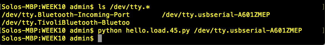 And it should run fine.
If you wonder how to close python this is the command:
quit()
This is the video showing how the python responds with the touch from the input sensor.