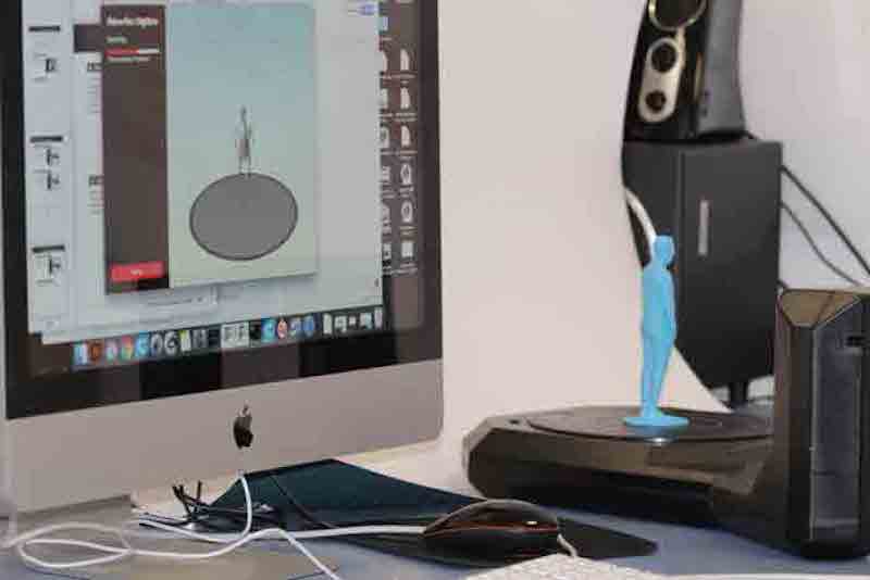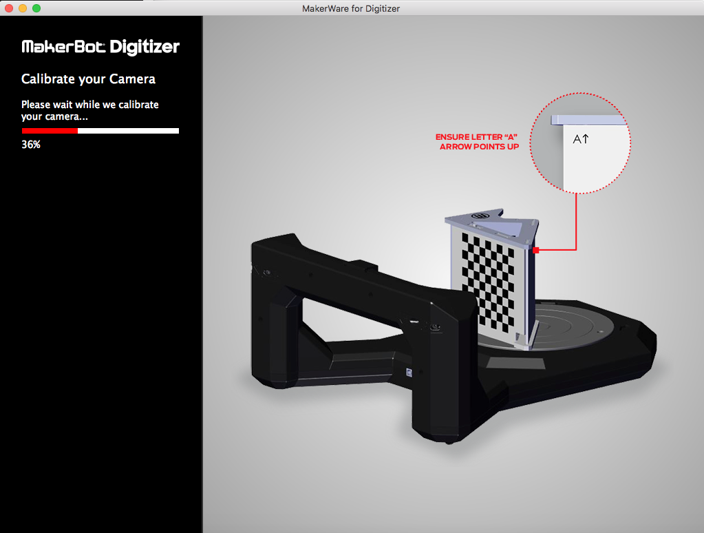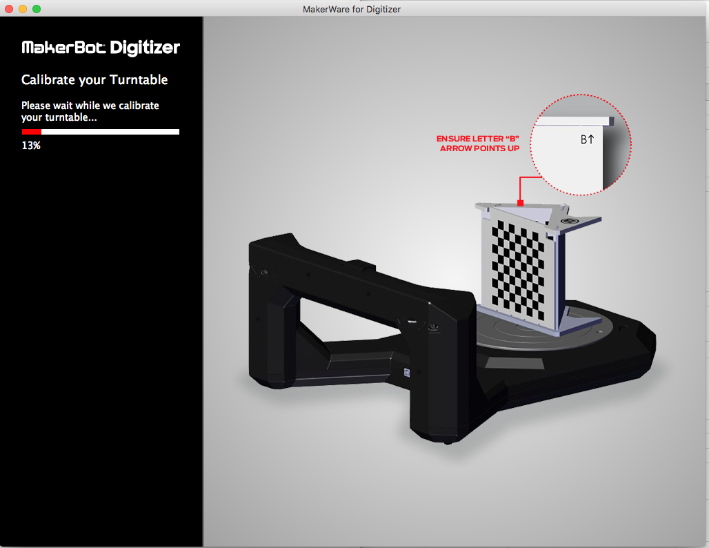
I used Skanect Pro software with an ASUS XtionPRO depth sensor for 3D-scanning. I also experimented with Makerbot Digitizer which is a desktop laser 3d scanner.
The setup requires a computer with a decent graphics card to capture the 3D and image data at a reasonable framerate. Running with a basic PClaptop achieved <10 frames per second (fps), meaning the sensor must be moved around the object veeeery slowly to avoid interruptions in the scan. Once set up on a more powerful machine with a good graphics card, we managed >30 fps making the scanning much more stable.
I wanted to scan an object that warrants using a 3D scanner - something with geometric complexity that is difficult or impossible to model in CADsoftware. From previous experience, 3D scanners are not very good at capturing simple objects precisely (like a simple cube for example). These objects are much more easily, quickly and accurately modelled in CAD.
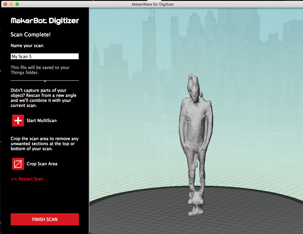
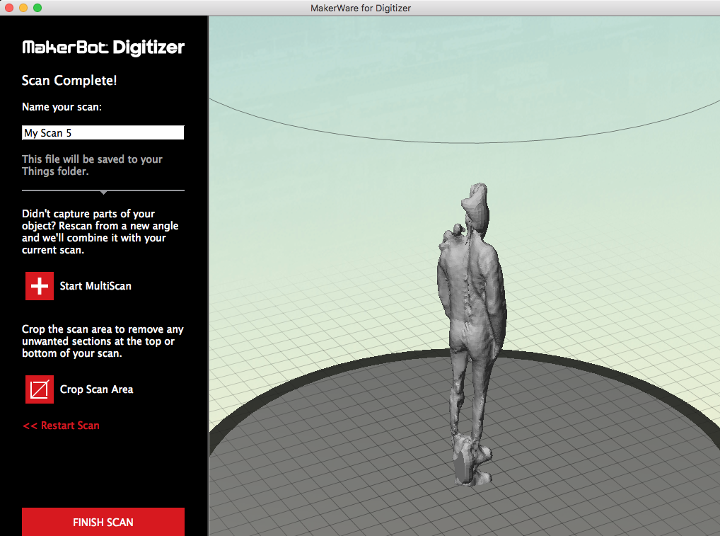
I decided I would scan myself, which I could later 3D-print as a coathook or statue.
Skanect Pro + ASUS XtionPRO setup
First I cleared some space and placed a rotating stool in the middle of the scanning area to use it sit still for a few minutes whilst scanning.
 Setting up the scan with Skanect
I first made a test to check everything was working well. Before starting the scan, it’s important to make sure the object is positioned close to the centre of the scanning area on screen. Pan around to check the position front-to-back and left-to-right before initiating the capture. Any geometry outside the scanning are will be clipped.
 Test scan of myself - the scan captured only the front side as I was not in the bounding box.
Scanning my own body was going to be logistically challenging. I needed an assistant. Luckily Niklas, A colegue at Aalto Fablab, was happy to help.
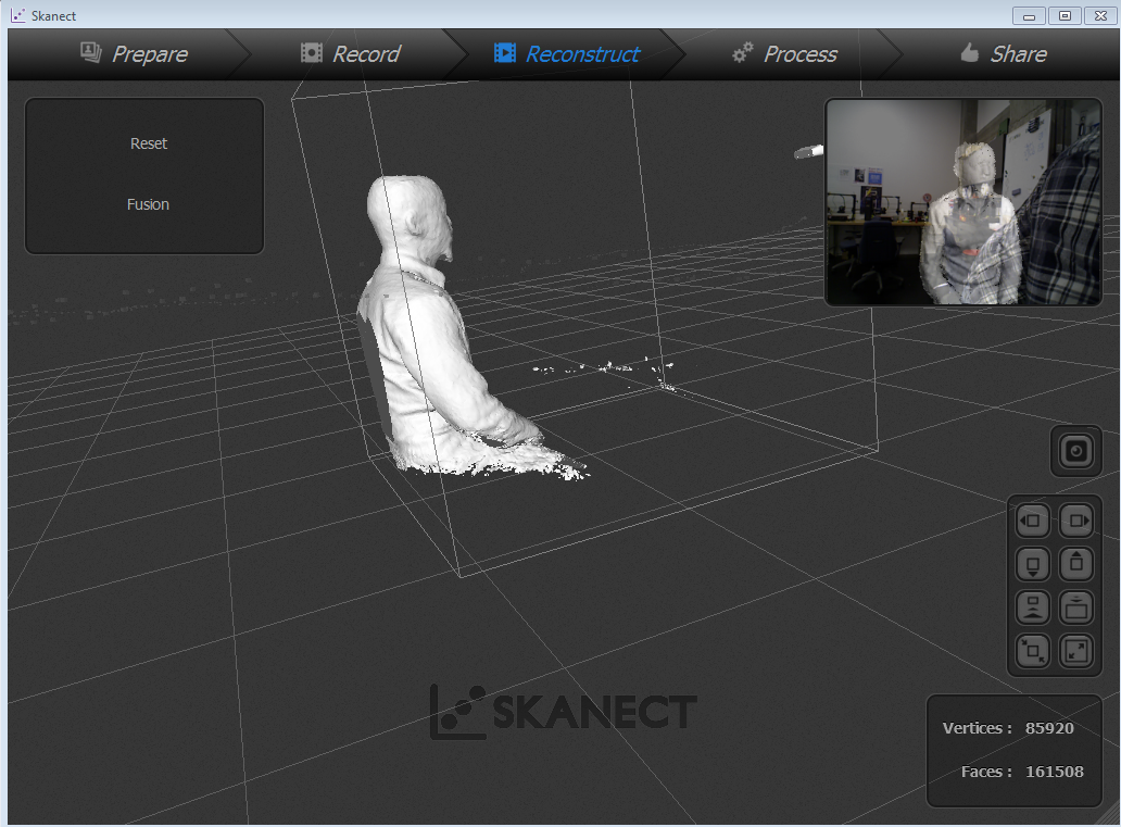
 The scanning in progress
As Niklas kept the scanner in a stationary position I sat down on a rotary stool and try to keep my self rolling on a slow pace as much as possible trying to circle around a vertical axis: That is quit a chalenge as one tends to loss the center of mass.
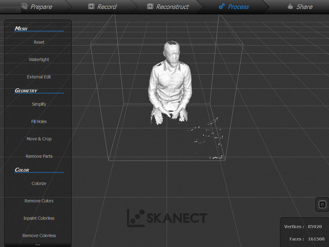
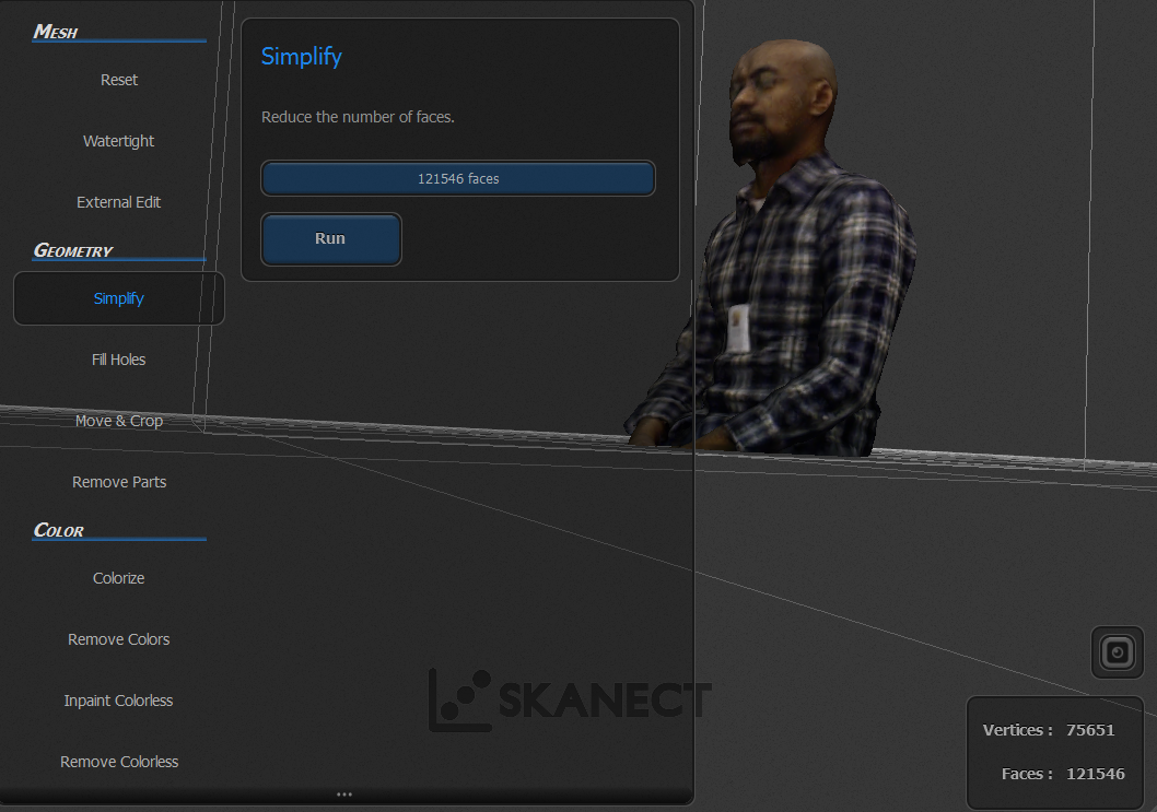
 Post processing the scan
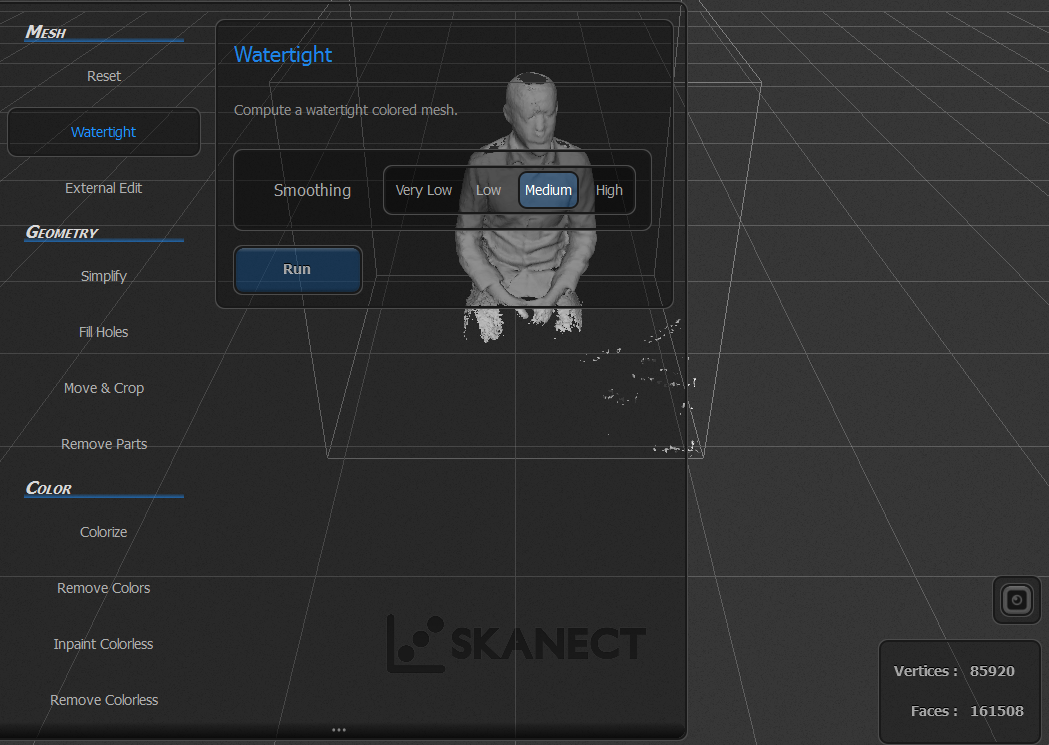
The scan was post-processed in Skanect, first using the Watertight function to seal any holes in the mesh (important for 3D-printing), and then using the Move & Crop tool to straighten up the object and clip it flat to the ground plane.
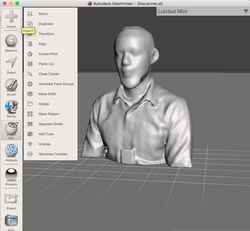
Using scanect software. There is not that many options in the process, first you make the scan, make some minor improvements like closing surfaces etc. and finally save the scan file or export the file to .stl or .obj-format for futher mesh editing in softwares such as Meshmixer.
Pros and Cons of using a Depth Sensor for 3D Scanning
In my opinion, using a depth sensor is the easiest way to start 3D scanning. It requires very little technical knowledge because the process is very interactive.
+ No need to worry about the background
What’s great about a depth sensor is that it actually senses depth.
That means that the software can tell it to only capture the object or
person — and ignore the background. Because of this, the background
doesn’t matter at all. There can even be people moving in the
background!
+ Interactive Progress Preview
The sensor software overlays a preview of what is being captured
on top of the camera feed. This way you know exactly which parts have
been scanned to ensure you cover everything to generate a model without
holes (extra important for 3D printing).
+ Fast results
Scanning an object or person can usually be done within two minutes.
Processing time depends on the software and computer that’s being used
but is usually done within minutes.
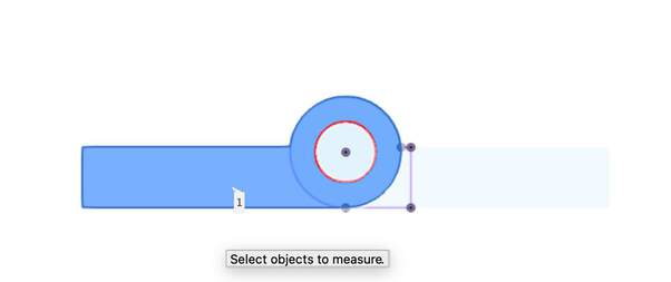
+ To Scale by default
Depth Sensors are factory-calibrated and know exactly how far objects
are. Sensor scans are usually great for doing interactive measurements
that don’t require industrial (sub-millimeter) accuracy.
– Don’t work well outdoors
this depth sensor uses a small infrared laser projector. This light is
invisible to the human eye, which is convenient and safe. But the small
projector isn’t as powerful as other infrared light sources like, let’s
say… the sun. You might be able to capture on a very overcast day but
any direct sunlight messes up the depth sensing capabilities.
– Limited Scan Range & Object Size
There are different kinds of depth sensors but this ones
here is called short-range sensors. This means they can sense
objects from a distance of 20-40 cm up to 100-300 meters. This limits them to medium to large objects and
people. I’d say anything from 40 – 250 cm tall is the ideal scan size
for this depth sensor subjects.
– Limited Scan Quality
I determine scan quality by both looking the geometric details and
texture quality. These depend largely on the resolution of the cameras
that are used. Without becoming too technical: these sensors use an
infrared black-and-white camera to capture the patterns projected by
the infrared projector and and a RGB color camera to capture texture
information.
The quality of a depth sensor scan can be considered a low-poly 3D model. It might not be the best scan result but the fact that it’s “light” means it’s perfect for realtime 3D purposes such as online sharing, VR/AR applications, body measurements and small-scale decorative 3D printing (e.g. miniatures in full color sandstone).
The quality of this set up could have been greatly improved with the use of a large, Automatic Turntable. That way one can controll the speed of the scan and get a larger freedom of rotation compared to sitting in a turnning chair and trying to rotate in a vertical axis. A future project for lab development.
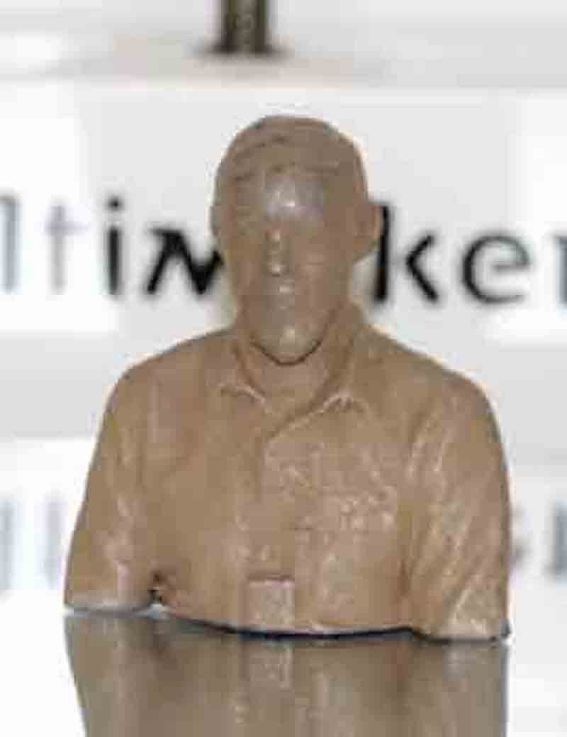
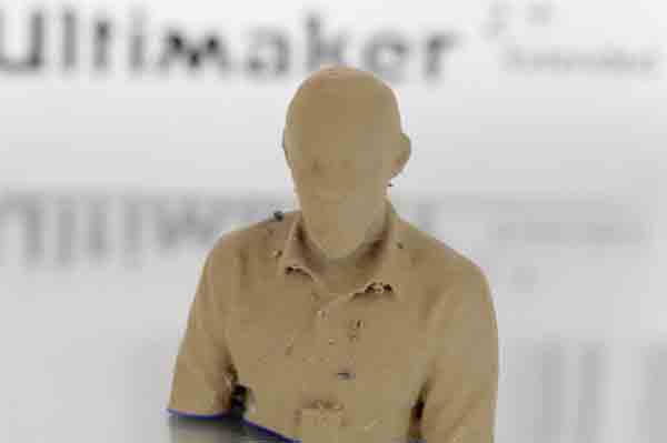
 colour mapping
really brings 3d-scanned objects alive
colour mapping
really brings 3d-scanned objects alive
I made a minor adgestments on the file using Meshmixer.