Testing & Results
Stepper Motor Testing: TMC2208SILENTSTEPSTICK Driver board
The datasheet from TRINAMIC Motion Control describes the chip as a microstepping driver with translator. The IC is capable of driving bipolar stepper motors in full, half, quarter and eighth-step modes and output drive is limited to 30V and 750 mA. The chip also includes thermal shutdown and crossover-current protection.
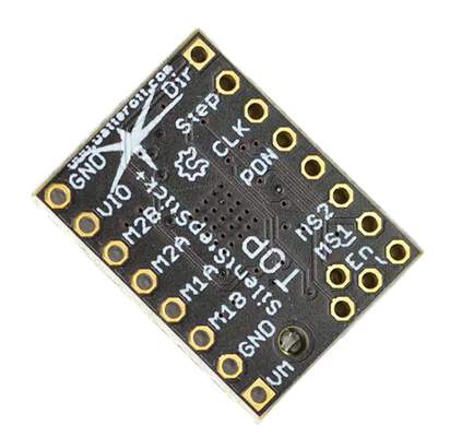
The amount of microstepping is controlled by the MS1 and MS2 inputs. MS1 and MS2 are both hard-wired to 5V, which puts the IC in eighth-step mode. The Enable input is active LOW. When /EN is HIGH, the driver outputs are disabled. The drive the motor, pulses are sent to the STEP input. Direction of rotation is controlled by the DIRECTION input pin.
The maximum current limit is set by the selection of Rs and Vref, with Itrip(max) = Vref/8Rs. Since I am using Vref = 1.854V (measured, adjustable via 10k potentiometer) and Rs = 0.5 ohm, this gives me a maximum trip current of 0.4635A.
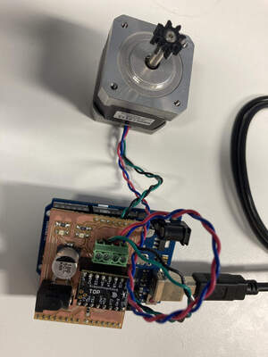
To test the stepper driver board, I wrote a simple program to continually drive the stepper motor in one direction, then in the opposite direction. The setup code for this program is displayed below:
/*
 * Testing A3967 Stepper Driver
 * w/arduino as controller
 * STEP - Pin 2
 * DIR  - Pin 5
 * /EN  - Pin 8
 *
 * Motor: 200 steps/rev
 *        1/8 microstepping
 * Gives: 1600 steps/rev
 */

#define xstep 2
#define xdir 5
#define enable 8
int cnt=200;

void setup() {
  // put your setup code here, to run once:
  // configure I/O pins
  digitalWrite(xstep, LOW);
  digitalWrite(enable, HIGH);   // disable motor at start
  pinMode(xstep, OUTPUT);
  pinMode(xdir, OUTPUT);
  pinMode(enable, OUTPUT);
}
This is followed by the actual code to drive the stepper motor, placed within the loop() function:
  digitalWrite(enable, LOW);    // enable driver

  digitalWrite(xdir, LOW);
  for (int i=0; i<cnt; i++)
  {
    digitalWrite(xstep, HIGH);
    delay(1);
    digitalWrite(xstep, LOW);
    delay(1);
  }

  digitalWrite(xdir, HIGH);
  for (int i=0; i<cnt; i++)
  {
    digitalWrite(xstep, HIGH);
    delay(1);
    digitalWrite(xstep, LOW);
    delay(1);
  }

  digitalWrite(enable, HIGH);   //disable motor
Stepper Motor Testing: 3-axis control using Grbl Shield
Once I managed to successfully drive a single stepper motor with my controller board and the stepper module, my next challenge was to drive 3 motors, representing the X-, Y- and Z-axis. I decided to test this on the grbl shield i made, as I wanted to verify the operation of this setup with the TRINAMIC modules.
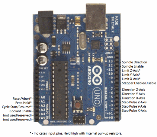
For this test, I decided to use the same pin configuration as the default grbl controller setup:
The program code is essentially the same as that for driving the single stepper motor. I initialized the controller pins for the step & direction for the 3-axes, then exercised each of the axis in turn by sending a pulse train to the respective stepper motor.
Programming Grbl Software to Controller Board
Since my CNC router not only had to be low-cost but also easy to use, I decided to use the opensource grbl control software for the gcode interpreter. Grbl is a highly optimized gcode parser and CNC controller that runs on the arduino platform.
There are 3 basic ways to program grbl into the microcontroller board:
- 1. Using the Windows-based XLoader application
- 2. Using an ISP programmer to upload pre-compiled grbl hex code
- 3. Compiling from grbl sourcecode on the arduino IDE
A quick grbl setup guide for Windows using Xloader can be viewed at the Protoneer blog site. The site also contains links to both XLoader and a pre-built hex version of Grbl.
The second approach, using an ISP programmer, is the usual standard way of programming any pre-compiled hex code to an avr device.
The third approach requires downloading the arduino sketch version of Grbl. The Grbl-Arduino library can be download from the Protoneer GitHub site. Once the Grbl-Arduino library has been downloaded, install it as an Arduino library in the usual way. Open the Grbl file from the Examples --> GRBL folder.
The grbl setup.h file has to be modified as per the pin configuration of my GRBL board layout and the pinouts on my Mother board so I modified the setting.h file inside the GRBL folder. As seen on thee video below, I used Atom to edit the pinset up save the file, refrashed the Arduino API and now am ready to upload GRBL.
Compile and upload the file to the arduino-based board.The Machine Control tab displays a jog controller, where you can control the movement of the X-, Y- and Z-axis by clicking on the appropriate button. This screen also allows the user to set the work coordinate system (zero-points).
The File Mode tab allows the user to load a g-code file, visualize the cutpath before sending it to the Grbl controller. The middle mouse button shifts the workpiece in the visualizer. The right mouse button rotates it. Clicking the Send button will send the g-code to the CNC. The cutting process is displayed in the G-Code Visualizer window.
Calibration of CNC Machine
Before the CNC machine can be used, the X-, Y- and Z-axis has to be calibrated. The X- and Y-axis stepper motors came with integrated threaded screw rods and are from the MTM sets that we purchased for our fablab. I did not have the specifications for the threaded rods, but I recalled vaguely that Nadya mentioned something about the rods having 4 threads, instead of the typical single thread. Looking through the code for single_node.py from the MTM build, it seemed that the motors are 1.8 degree per step and the rods give 6.096mm/rev. Since I configured my stepper drivers for 1/8 microstepping mode, this gives:
    motor steps/rev = 200
    number of microsteps/step = 8
    thread pitch = 6.096 mm/rev
    effective step/mm = 200*8/6.096 = 262.47
Similar calculations for the Z-axis yields:
    motor steps/rev = 200
    number of microsteps/step = 8
    thread pitch = 2 mm/rev
    effective step/mm = 200*8/2 = 800
Using those values as a starting point, I configured my Grbl controller:
    $0 = 262.47
    $1 = 262.47
    $2 = 800
To perform the calibration test, I fixed a pencil to the Z-axis motor mount and a sheet of paper on the base plate, then used the Jog controls to draw 10mm lines in the X- and Y- directions. I also wrote a simple G-code program to draw a 10mm x 10mm square and sent it to the machine. I adjusted the values for steps/mm until I could draw a perfect square with the right dimensions.
Calibrating the Z-axis required a different approach, as I could not measure the movement of the pencil point accurately. I finally settled for making a mark on the linear support rod, then moving 10mm in the Z-direction and repeating the motion until I had the Z-axis calibrated.
To test the settings, I decided to import the g-code for one of the PCBs that I did earlier and draw it on the paper. The results were a bit of a letdown, as the pencil was not rigidly fixed onto the Z-axis mount and had a bit of free play.
Results: Test RUN using Pen
As can be seen from the test drawing below, my CNC router has not been fully calibrated yet. However, since I had a presentation coming up on 11 June, I decided to go ahead with a test run on paper.
I had previously designed a simple part in Fusion 360 and generated the CAM files for this part and simulated the milling operation.
I then proceeded to load the gcode file in Universal G-code Sender and sent the job to my CNC machine. The surfacing operation went OK, but there are still some issues with the pocket milling operation. I've included a video of my whole design and build process, which I presented on 22 June.