WEEK 8 - Computer-Controlled Machining
TODOs for this week
☑ Design and make something big on a CNC machine.
☑ Explain how the files for machining were made.
☑ Show how the object was made.
☑ Describe problems and solutions.
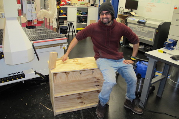
☑ Include design files and a ‘hero shot’
☑ Group assignment: Test the CNC machines capacities
Recontech 1312
Our shopbot version large scale CNC machine is 1200 x 1200 in the xy and a maximum z height of 900mm.
The setup is runned with MACH 3 for postprocessing.

Recontech 1312
|
|
||||||||||||||||||||||||||||||||||||||||||||||||||||
|
||||||||||||||||||||||||||||||||||||||||||||||||||||
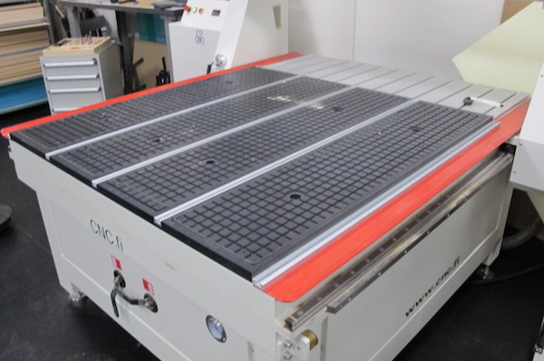
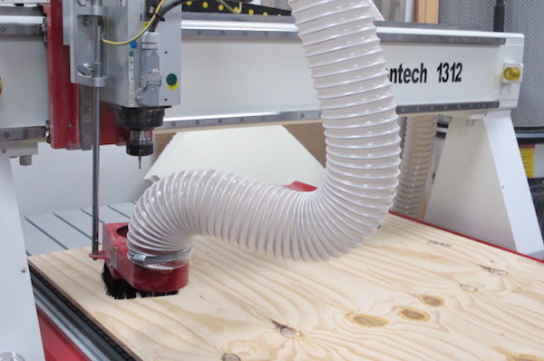
A vacuum table for a convinient attachment.
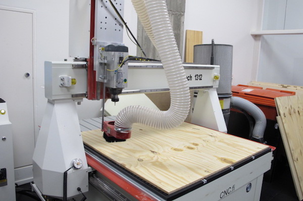
Dust extraction for removing the chip.
Inspirations and few examples from Our lab

3d data visualisation
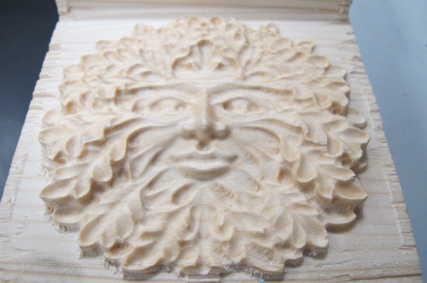
More intricate 3d subtractive manufacturing

very useful tool organiser for our CNC tool set
4 AXIS-MDX 40
The Other CNC family we have the lab is the 4axis Ronald mdx 40. This is a small build area machine but it gives a possiblity to make amazing things from softer materials such as wood.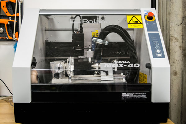
MDX 40 4th-axis cnc
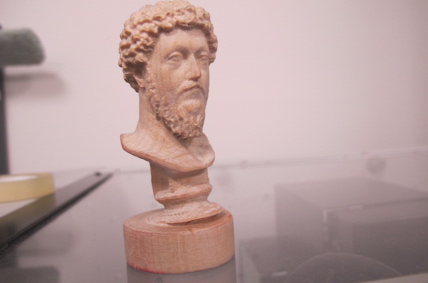 An example piece made using the 4th axis cnc
Make something big
Design a 3D model to be milled
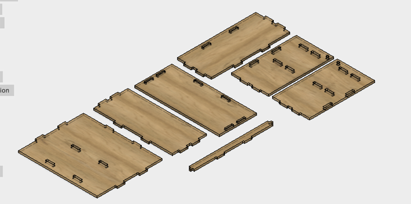
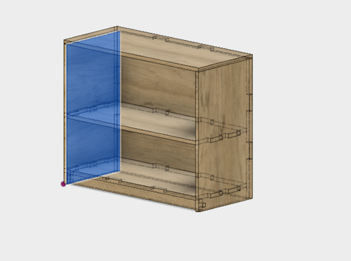
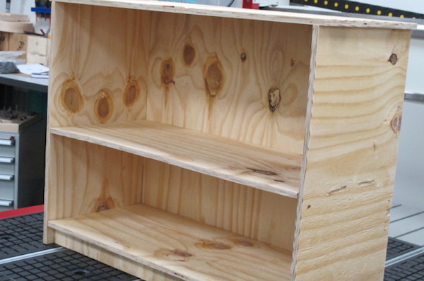
I decided to use Fusion 360 to create the model to be milled. I wanted to build something for our lab and I thought a shelf would be a good idea to organise things better in the lab.
Designing with Fusion 360
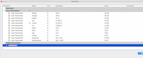
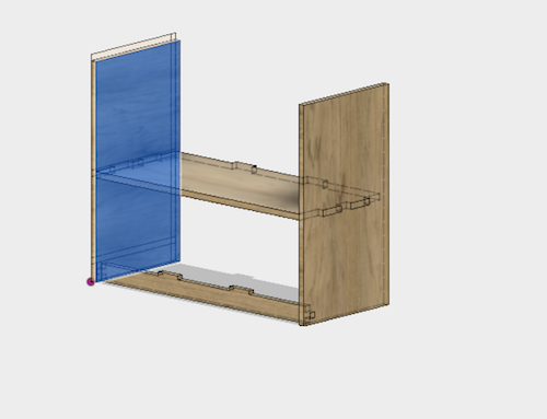
I did the whole design using Fusion. The shelf will have 7 different pieces. The lateral walls (that will be mirrored objects, the back wall the top, the two partition shelfs and the support leg. I utilized tabs and holes as joints. I added a groove to insert the sit in the laterals. I utilized parameteric design utilizing the stock thickness and the over all length of the chair as the main parameters.
Next I will explain step by step the modelling process:
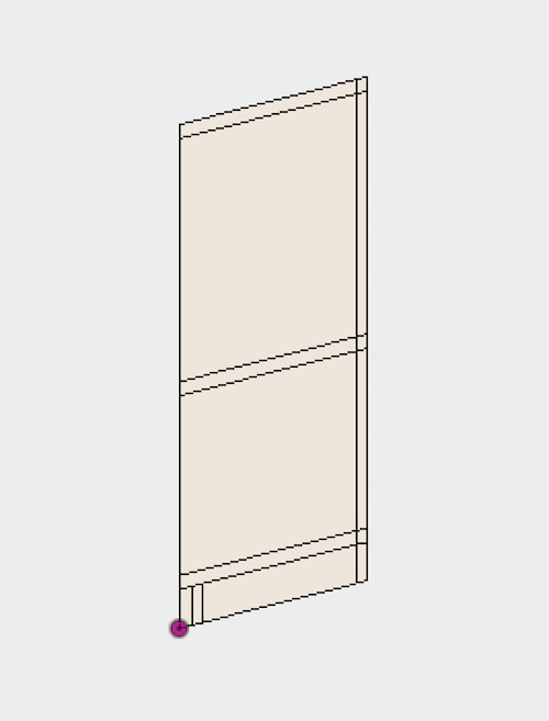
Lateral walls
No major difficulties in the design. In the sketch
I used the
rectangular slots with two centers (Sketch >
Slots > Center to Center Slot)
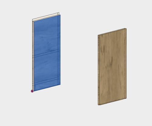
Back wall
The back wall was made in a similar way as the shelfs wall. I drew vertical and horizontal auxiliary in the center of the rectangle (utilizing the midpoint constraint and transforming the lines into Construction lines through the contextual menu.
I then Lay down all the peaces to the xy constraction plane to export the file in the dxf format.
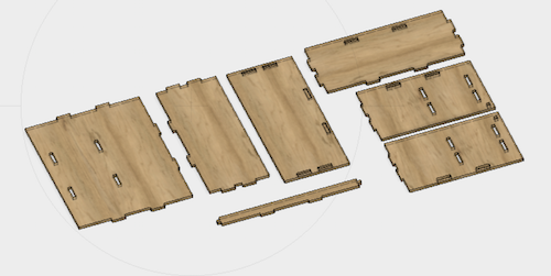
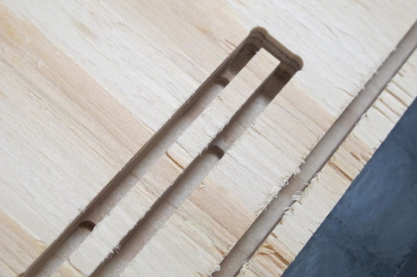
dogbones
Next step is to create the dogbones to creat a clean 90 degree cuts with out the tool size getting on the way of the internal angles. After studying different options, and considering that I did not have that much time for trying different ones, I opted to use an open source add-In called DOGBONE.
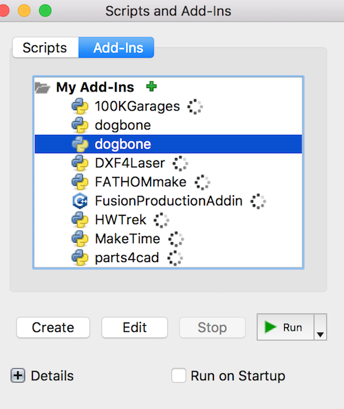
This should avoid the limitation when trying to make 90 degrees angles. The bit goes so close to the angle that creates certain circular edge instead of a straight angle. To overcome this problem, I give all angles certain curvature so the bit can do the right movement. I runned the dogbone script from the modify menu. Choice the parts the I wanted the bones to be add and applied.
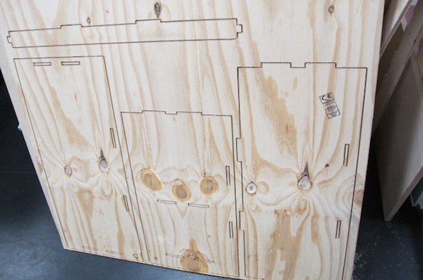
I exported the file to a dxf formate and my job in fusion is done.V carve studio
I imported the Dxf file into the v varve and set my work space to 1200 x1200 and the material tickness of the wood to 13mm
The Dxf file is too big to fit to the maximum cutting size of the machines bed. So we need to do the cutting operation in two parts
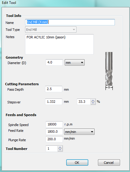
The tool I have decided to use that works optimaly with the dogbone I created was the 4mm Endmill
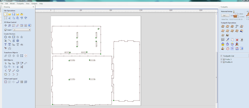
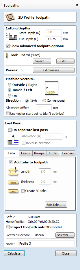
The toolpath for this work is mostly a 2d Profile. So I choice the operation from the right side pop-up and adjust the settings for the cutting depth and added Tabs to the corners of the piece so that the piece wouldn't fly away whrn it is cut all the way.
After completing the tool path calculation for all the geomery we want to cut. It is time to Export the g code with the fight postporocessing extention. Our machine Uses MACH 3 to talk to the computer and heńce we use these post processor
Preparing the pieces for CAM
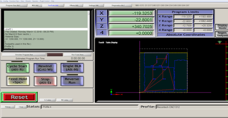
Here we can see the toolpath and one can simulate the dirrection the tool would follow for quick debugging
If everything looks the way it should, it is time to set the home position of the machine , Zero the x,y and Z positions, load the piece and start cutting.
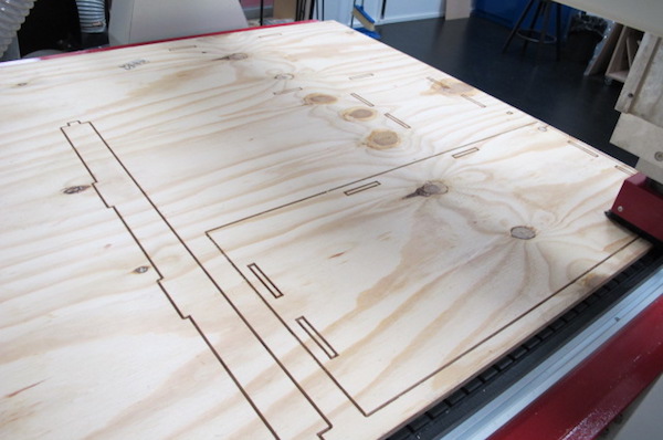
Finally, I did the same thing for the other half of the remaining pieces. And the MAchining job was done.
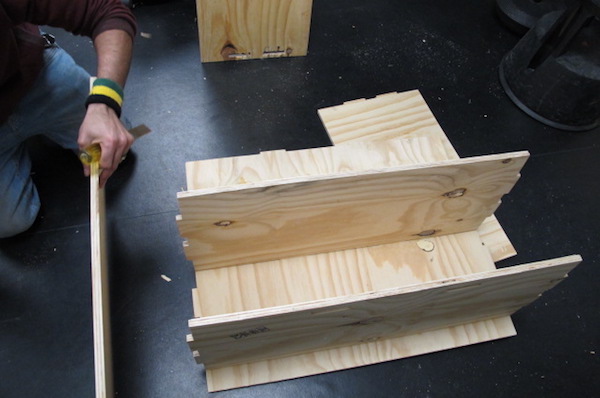
This was more challenging than I thought as the piece has bended overnight from humidity and the cutting dirrection has made some pieces to bend even in more than one dirrection.
With A great help from my collegue Jason and a rubber mallet, I finally managed to put the pieces together.
Issues I found
I used always objects, and never assemblies. For creating the tabs, it might have been better to join the objects using the assembly instead of the objects.
Safety is real important in operating the machine and double, triple check everything is in the right order. Pay attention to how the machine sounds. You can tell if the machine is running in the wrong setting or a losely attached cutting bit if you get familiarized with the normal operation.
- The CNC router must be operated by at least 2 people. There should be always one people ready to shutdown the machine if an accident happens.
- No bracelets, necklaces, longhair. Anything that could get caught on the CNC router must be avoided.
- Use always protective glasses. Ear muffs are recommended.
- The suction must be activated always while operating the machine so all dust can be removed.
Link to this weeks group assignment testing Runouts and comparisons between Climb Vs Conventional milling we did with Kitja and Ranjit : Group assignment
Files
BOOKSHELF FUSION FILE -
BOOK SHELF
DXF SHELF -
shelf.dxf
V CARVE FILES -
shelf.crv
G CODE FILES -
Profile.txt
Profile2.txt