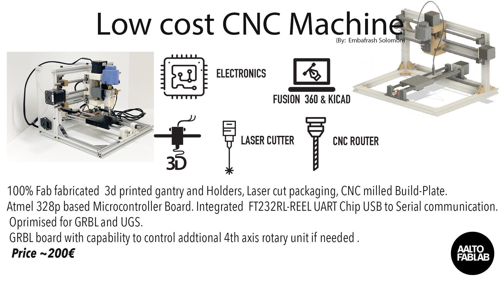
Click to see the Video to my final presentation video and and on the Slide to view my presentation concept, which gives an overview of the different components of my low cost CNC machine and how they are linked.
an overview of the different components of my low cost CNC machine and how they are linked.As can be seen from the test drawing below, my CNC router has not been fully calibrated yet. However, since I had a presentation coming up on 11 June, I decided to go ahead with a test run on paper.
I had previously designed a simple part in Fusion 360 and generated the CAM files for this part and simulated the milling operation.
I then proceeded to load the gcode file in Universal G-code Sender and sent the job to my CNC machine. The surfacing operation went OK, but there are still some issues with the pocket milling operation. I've included a video of my whole design and build process, which I presented on 22 June.
My final project implementation was only partially successful. The basic framework and mechanisms of my CNC worked. My Grbl controller board and stepper motor drivers worked well. The areas which needs improvements are the calibration of the mill. It is still not accurate enough yet. The build plate also needed to be surface milled.. I used two fixed mount screws for the spindle motor. In retrospect, I should have gone for a more reliable joint than a screw mechanism on a 3d printed part. That will not hold a lot of torque and nota rigid mount. I would also like to redesign the mount, so that it is more generic and can take different types and sizes of end effectors.
My Grbl control board is able to take limit switches mounted on the 3-axes, but these have not been implemented yet. Another area which I would like to improve upon is the test out my arduino shield compatible ATmega328 board. During the course of the project, I felt that I have been very careful when wiring my system. However, despite that, I stil managed to connect the wires wrongly on a few occasions.
My explorations on low-cost digital fabrication machines which can be made in a fablab will not end with this CNC router. I intend to do further work in this area and build up our expertise in building a range of different types of machines, such as CNC mill, router, PCB milling machine, 3D printers, laser cutters, 3D scanners, vinyl cutters and other machines useful for digital fabrication.
I had so much problems with 1.5mm rivets being to close to each other. I really would work on open source electoplating machine