
Networking And Communications
Individual assignment:
Group assignment
Our group assignment can be found here.
Individual assignment
- Design, build, and connect wired or wireless node(s) with network or bus addresses
Testing with Arduino Uno
Earlier on this course we have had one host and a project and TX and RX going in between them. This week in addition to host computer/board we need number of nodes. They are all connected the way presented in the next picture from Neil’s lecture)

The host thinks it is just talking to TX and RX but the lines are shared. One TX goes out to each node but the RX is shared so there would be a “fight” if multiple devices try to talk at the same time. To fix this, each node is going to be initially in tri-state X (disconnected) which means it is listening to the pin, not talking to it.
Each node is going to have an ID hardcoded (it’s network address). The node waits to get a character and if maches its address, the listening mode pin is set as an output to put out a message and flash the LED and then put back to listening the pin.
Since I am more familiar with Arduino Uno board, I have to use a single arduino to understanding the assignment better. The same principle can be used for multiple boards by giving them a different network address. I also didn't use FTDI-USB cable at this testin g fase and accessed my node with USB connection.
The Arduino hardware has built-in support for serial communication on pins 0 (RX) and 1 (TX) (which also goes to the computer via the USB connection). The native serial support happens via a piece of hardware (built into the chip) called a UART. This hardware allows the Atmega chip to receive serial communication even while working on other tasks, as long as there room in the 64 byte serial buffer.
I used Arduino Simple Software Serial tutorial and Jari’s page as a reference for designing my network.
Code for controlling the node is
#include
#include
#define BUTTON PIN_PA6
#define LED   PIN_PA7

SoftwareSerial mySerial(2, 3); // RX, TX (ATTiny DIGITAL/ANALOG pin number)

const char node = '2'; // network address
int incomingByte;

void setup() {
  mySerial.begin(9600);
  pinMode(BUTTON, INPUT);
  pinMode(LED, OUTPUT);
  pinMode(3, INPUT);
}

void loop() {
  if(!(digitalRead(BUTTON))) {
    digitalWrite(LED, HIGH);
    pinMode(3, OUTPUT); // open line to write
    mySerial.print("node ");
    mySerial.println(node);
    pinMode(3, INPUT);
  }

  if (mySerial.available()) {
    incomingByte = mySerial.read();
    if (incomingByte == node) {
      digitalWrite(LED, LOW);
    }
  }

}
What the code does?
#include <SoftwareSerial.h>
The SoftwareSerial library has been developed to allow serial communication on other digital pins of the Arduino, using software to replicate the functionality (hence the name “SoftwareSerial”). It is possible to have multiple software serial ports with speeds up to 115200 bps. A parameter enables inverted signaling for devices which require that protocol.
SoftwareSerial mySerial(2, 3); // RX, TX
RX and TX pins are2 and3.
#define LED PIN_PA7; // the PIN number of the LED pin
On Attiny412 LED pin number is PA7.
#define BUTTON PIN_PA6; // the PIN number of the LED pin
mySerial.begin(9600);
The bound rate is set to 9600.
const char node = '1'; // network address
I’m naming this ’s network address as ‘1’. The other 2 boards are name 2,3,… etc.
if(!(digitalRead(BUTTON))) {
    digitalWrite(LED, HIGH);
    pinMode(3, OUTPUT); // open line to write
    mySerial.print("node ");
    mySerial.println(node);
    pinMode(3, INPUT)
Here the board is putting it's led on with a comand from the Push button and then set the software serial pin 3 to output and send to serial monitor that the node is pressed and then change pin 3 Back to receive mode. Mind you at this stage the led will continue to blink....and keep listening for any more commands.
if (mySerial.available()) {
    incomingByte = mySerial.read();
    if (incomingByte == node) {
      digitalWrite(LED, LOW);
.
This last piece is very interesting as the pin awaits for a command to turn the led off from a command receive from serial monitor.
Making nodes using Arduino Nano and week 6 ATtiny 412 board
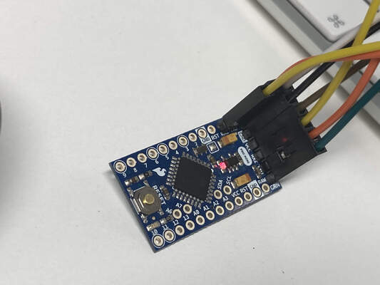
The hardware used in this exercise were Arduino Mini Pro board and two week 6 boards to build the bus.
Here is a quick preview video from Week 6 programming ATtiny 412 board using UPDI programmer that we will be using for the next experiment. the video shows ATtiny 412 board blinking according to push nof button as per the code.After milling and Soldering a second ATtiny412 board I moved to main part of this weeks assignment
On the Code side, I set Arduino Mini to be Node 1, and my two LED/Button boards to be Node 2 and Node 3. I uploaded the codes using FTDI cable for the MIni Pro and UPDI programmer for the 2 boards.
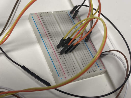
I then wired the boards with a bread board for an easy connection solution.
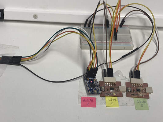
After these modifications the system worked the way I wanted: when I type 1 in serial monitor, the Nano blinks and prints Node 1 to monitor and when the button on board 3 is pressed the LED blinks with a notification on serial monitor that the board is pressed and continue to blink Untill number 2 is sent to serial which will turn off the led on this board and Turn on the led on Board 2 (node 2)as seen on the following video.
The Boards blinked only when the incoming byte matches the pin number.
Reflection
I learned the basic principles of how networking and communication works. I used pretty great amount of time finding explanation and examples how to apply networking and communication on one Arduino board. I wasn’t able to build a complete bus with just one Arduino board. After figuring that out I learned to write a code that I can use to build my own network without facing much trouble.
I had a problem with the code as when I was trying to read the serial information while the led was lit as there were two if statements that were not in the same loop.
My local instructor Kris explained to me that the listning function should be made available outside of the if statement of the Button press.
Files
Code for Arduino Nano - Node1
Code for LED/Button board 1 - Node2
Code for LED/Button board 2 - Node3