The Build Process
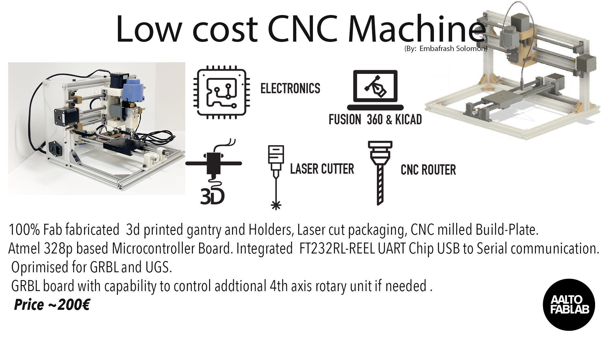
Click on the link to view my presentation slide, which gives an overview of the different components of my low cost CNC machine and how they are linked.
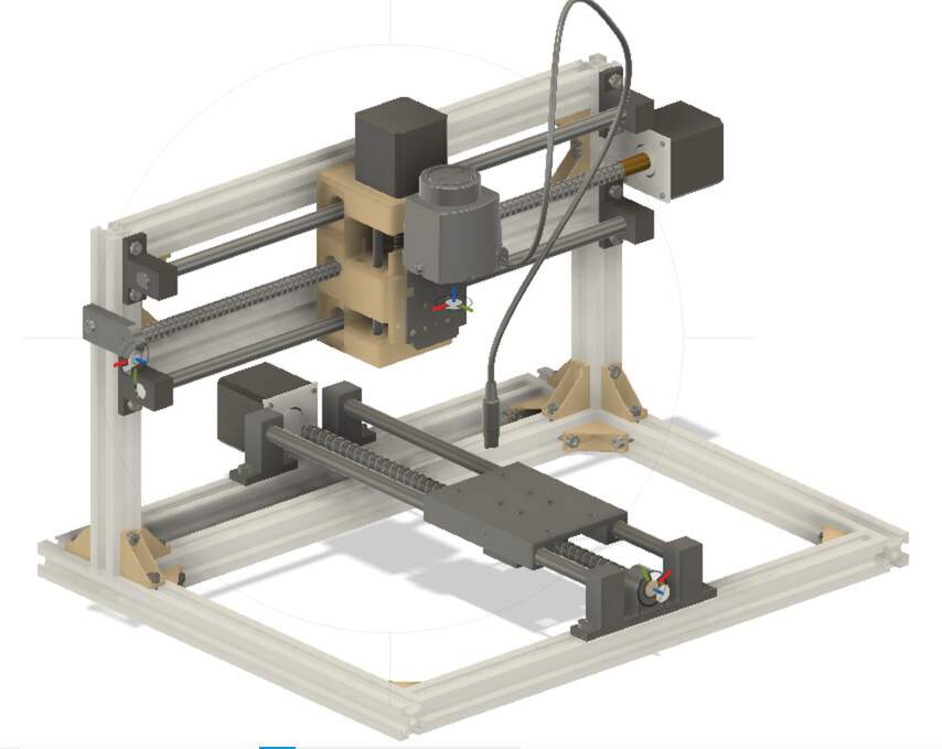
Mechanical Design
After much deliberation, I decided to build the frame of my CNC router out of aluminum profile, rather than wood. I chose aluminum rather than wood for the structure because it is stronger, more rigid and quality is more easy to assemble with the right standard . Using the Al profile also helps to standardise the connection methods and eliminates any extra effort to fabriate non stardardized parts.
Another major decision that I made was to design a movable platform CNC router, rather than a gantry design. Since I wanted my build to be low-cost and portable, it seemed more appropriate as a first design. My gantry system will have to wait for another build.
The Frame
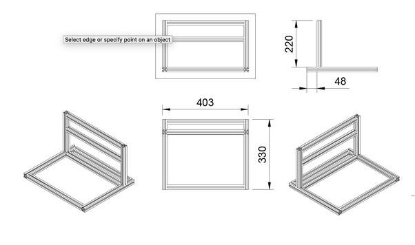
The dimensions of my frame were largely determined by the length of the threaded rods that we salvaged from old 3d printers we had in Aalto fablab. The original ultimaker 1 printers come with integrated 300mm threaded rods, so my x- and y-axis dimensions are limited to that sizes. I also opted to use 20x20mm aluminum profiles, which meant that the lengths of aluminum profiles needed were 290mm and 250mm.
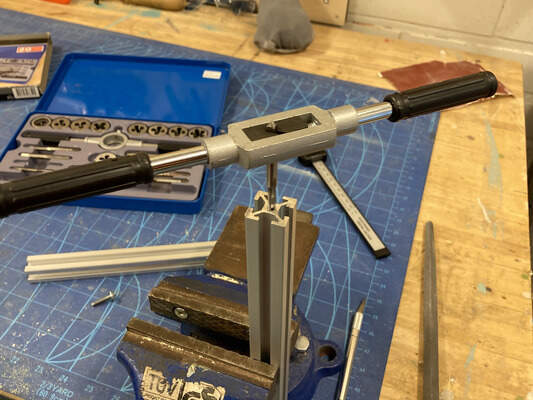
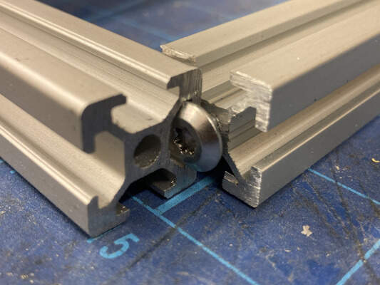
I modeled my Al profile based on the dimensions of the 20x20 Al extrusions. 90 degree angle brackets and treaded holes with T nuts where created to connect the profiles. I purhased the aluminum profiles, M4 bolts and insertion-nuts for use in the assembly process.
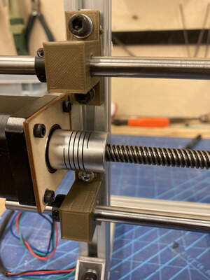
Neil wanted us to make as many parts as possible, rather than buy off the shelf components, so I modeled and 3D printed the 90 degree angle brackets, insertion-nuts, linear-rail shaft supports, linear bushings and 5-to-8mm flexible couplers. In the end, I opted to use the nylon bushings that came with the stepper motor kit, rather than my 3D printed version.
The CAD drawing of the 20x20 allumunium profile assembly for the frame structure with the dimensions is shown in the pictures below.
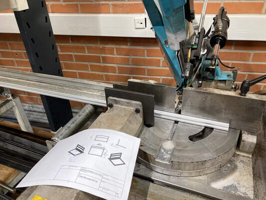
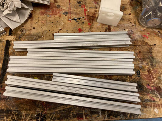
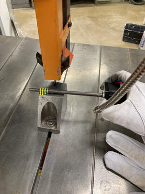
I was able to cut the extrusion very acurately using the Automatic metal Sawing machine we have in Our Matal workshop in aalto studios.
The frame is mostly connected to the guiding rails and the buildplate using these SK8 8mm Aluminum Linear Rail Shaft Guide Support Bearings shown below
Y-Axis Assembly
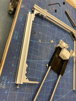
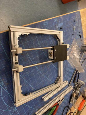
For my y-axis design, I designed the build plate to be connected via an anti-backlash nut with the threaded rod and the brass bushings for the linear support rails. I decided to keep the size of the Builtplate to 300x 180mm as this would give me more options on the final size of my work area.
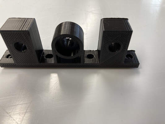
The linear shafts are supported by 3D printed shaft support pieces modeled after parts from the Mc Master catalog. The vertical height of the hole for the shaft support is 20mm and I designed the mounting brackets for the stepper motors to match that height. Likewise for the bearing support at the other end of the threaded rod. For the bearing support for the free end of the threaded rod, I used standard 608zz bearnings, which I "borrowed" from an old pair of inline skates that I had. If you look closely at the 608 bearings, you can see that the face plate on one side has been removed. I removed them for my inline skates, as it made oiling and cleaning the bearings much easier :)
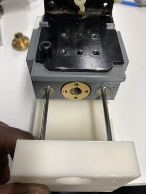
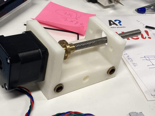
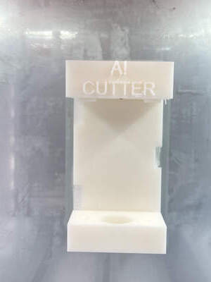
X and Z-Axis Assembly
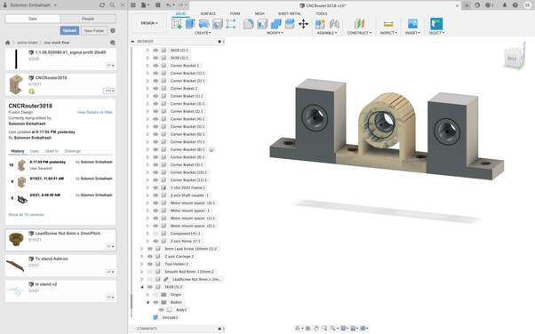
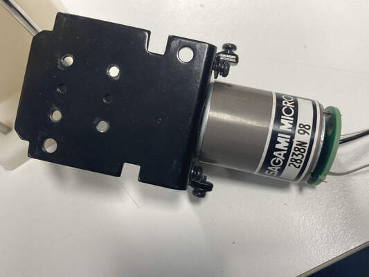
The X and Z-axis assembly are integrated as a unit. I designed this structure to be small, yet large enough to hold a reasonable size spindle motor or dremel tool. We had a nostalgic Ronald MDX 20 in the lab that has served us for over 10 years before it finally gave up last year so I recycled the perfctly intact Spindle unit as it comes with a full accessary of tool mounts both for 3 and 6mm tool shafts. It is also has my favourite way of zero-ing the Z axis by losing the setscrew on the shaft and letting the drillbit to drop touch the top serface on the material you want to mill. with this argument I went to deesign the tool holder for the spindle on the Z axis. Please note that this particular Spindle costs around 100€ on the official Ronald website. Which is quite expensive for the intended perpose of building a cost effective CNC machine. Quality always matters for the end effectors so no regrets there.
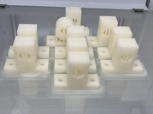
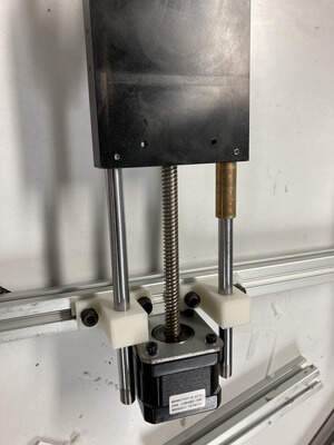
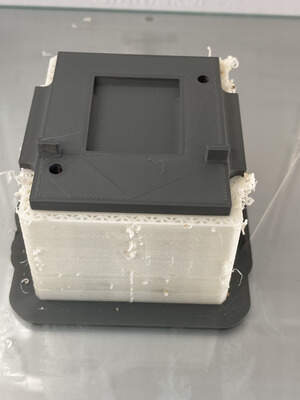
The z-axis structure holds the anti-backlash nut for the Z-axis threaded rod and the nylon bushings for the linear shaft. The structure was modeled in Fusion 360 and exported as Stl, then 3d printed using PLA and disolvable MP02024 filament from Makerbot. As this machine is essentailly a first prototype and I wanted to test if this was strong and rigid enough to support the spindle motor.
I originally intended to use a pair of linear bearing housing to hold the support plate for the z-axis motor mount. This resulted in a small misalignment in the mount, which restricted the range of motion of the z-axis, from the designed 60mm to around 40mm.
I then discoved a perfect and cheap souce of linear rodes to mount the Z axis using a linear bearing recycled out of a broken DVD player.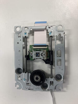
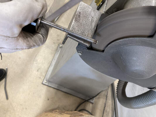
As the action to make the an affordable Machine proceeds, i had an issue with mounting the Z Stepper motor as the Motor came with a treaded rod that was too long for my design. So again thanks to the metal workshop next door I managed to trip and grind the edged as neccesary .
The x-axis structure holds the anti-backlash nut for the x-axis thread rod and the nylon bushings for the linear shaft. The structure was modeled in Fusion 360 and exported as Stl, then 3d printed using PLA. As a first prototype my main goal is to test if this structure is strong and rigid enough to support the whole assembly.
>
>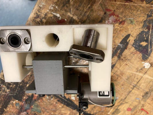
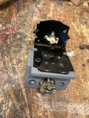
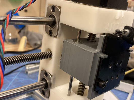
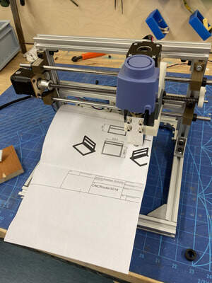
Motor mount plate and linear rail shaft support design is similar to that for the y-axis assembly. The pictures below show the final assembled x and z-axis mount.
The x and z-axis assembly was designed with a smaller width, so that my CNC router can have a larger working area. The effective working area for the movable bed is 180 (W) x 170 (D) x 40 (H) mm in the current prototype.
Electronics - Controller Board
I decided from the onset to use open-source software a much as possible, to keep the cost of my machine down. The software had to be user friendly and compatible with industry standard g-code. The hardware also had to be low-cost and readily available, either fabricated in-house in a fablab or bought off-the-shelf cheaply.
These design decisions led me to explore g-code interpreters running on an arduino-based platform. I decided to use grbl as the control software. Grbl is a popular open-source, embedded, high performance g-code parser and CNC milling controller that is highly optimised for Arduino uno platform. and hence dictated my choice of microcontroller to be ATMega 328p even though the chip could already be considered legacy Atmel Family.
I made my own version of Grbl shield as I will explain on the next steps, however many variant of the Sheild are available very affordbly on the market that plug directly onto arduino uno boards. These shields support the Polulu A4988 stepper drivers and these parts are readily available from many sources and are often used in DIY 3D printer builds. For example, Aliexpress sells a complete kit, including the arduino uno, cnc shield and polulu stepper drivers for USD14.34 inclusive of shipping.
Since I wanted my entire CNC router to be fabbable (i.e. can be made in a fablab, inclusive of the controller and stepper driver boards), I decided to also fabricate my own ATmega328 (arduino compatible) and stepper driver boards.
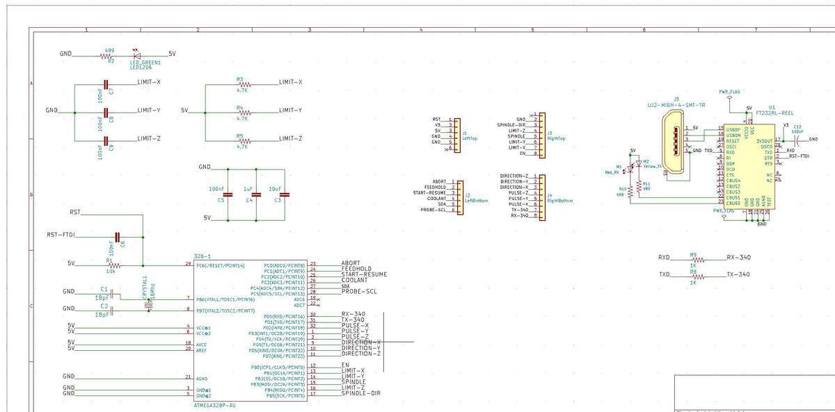
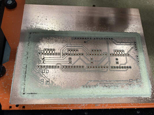
The main board is based on the satshakit-grbl board but Because I wanted to drive my CNC shield, I rewired the headers to match the normal Arduino GRBL pin out. I also want my board to have an integrated USB to Serial converter and added FT232RL-REEL UART. chip from ftdichip.com as it is the same chip used in the popular FTDI cables.This required the board to be 2-sided to make sure to have enough spacing for all the pins. This step was very frustrating as my revets were very close to each other and for some strange reason my macOS Big Sur stopped a driver support for this chip and the drivers downloaded from FTDIchip.com was no more identified. I had made 3 versions of this boad and non of them were identified by my Computer and I thought I made a design mistake untill I found others from DIY comunity were also suffering from the same cause. I changed to an older desktop and my board was identified.
1. Satshakit - Daniele Ingrassia developed this board during Fab Academy 2015 and has since come up with a few versions based on his original design.
The main board is based on the satshakit-grbl board but Because I wanted to drive my CNC shield, I rewired the headers to match the normal Arduino GRBL pin out. I also want my board to have an integrated USB to Serial converter and added FT232RL-REEL UART. chip from ftdichip.com as it is the same chip used in the popular FTDI cables.This required the board to be 2-sided to make sure to have enough spacing for all the pins. This step was very frustrating as my revets were very close to each other and for some strange reason my macOS Big Sur stopped a driver support for this chip and the drivers downloaded from FTDIchip.com was no more identified. I had made 3 versions of this boad and non of them were identified by my Computer and I thought I made a design mistake untill I found others from DIY comunity were also suffering from the same cause. I changed to an older desktop and my board was identified.
The Fabinventory doesn't have 16Mhz but have 20 Mhz crystals (Datasheet.(datasheet) and matching 10 pF capacitors (choosing capacitors 1 2) which would actually make the ATmega328p microcontroller (datasheet) run 25% faster. I googled around and it seems that with a 20Mhz crystal it should still work both as a Arduino clone (Source 1 2) and for GRBL (Source 1) provided that I compile the code for 20 Mhz and double check that all timings are correct. I couldn't find a straight up guide for how to make this work so I have to figure it out as I go. If I can't, then I'll order a 16Mhz crystal. UPDATE: I ended up ordering a 16 Mhz crystal and two 27pF capacitors and replacing them on the card.
>
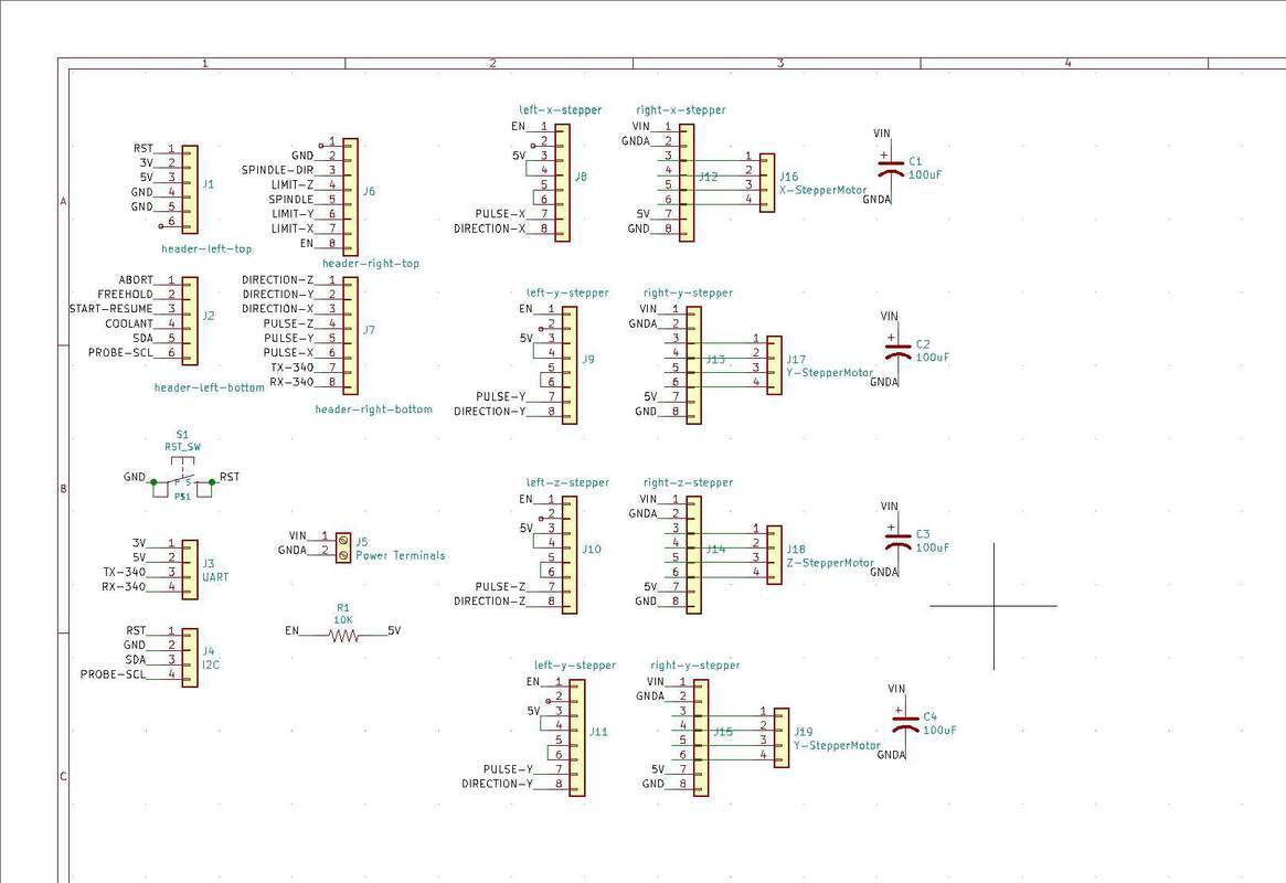
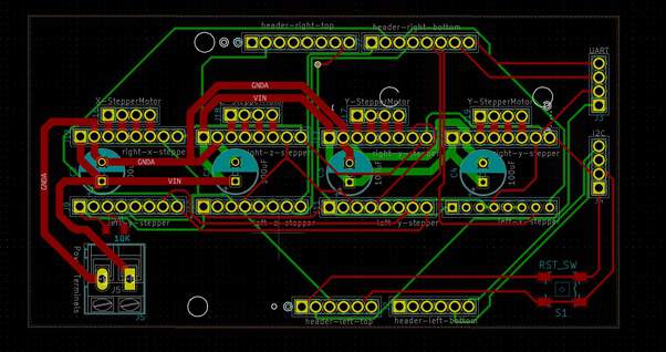
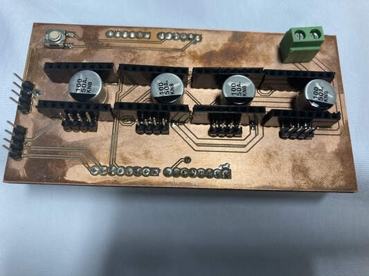
I am using the TI DRV8825 stepper drivers. I needed to build a shield to hold the drivers. The shield is based on the CNC shield.
- ISP Pin 1 --> Satshakit MISO
- ISP Pin 2 --> Satshakit VCC
- ISP Pin 3 --> Satshakit SCK
- ISP Pin 4 --> Satshakit MOSI
- ISP Pin 5 --> Satshakit RST
- ISP Pin 6 --> Satshakit GND
Once that was done, the arduino bootloader was programmed onto the fabricated controller board. This is done via the Arduino IDE's Tools > Burn Bootloader option.
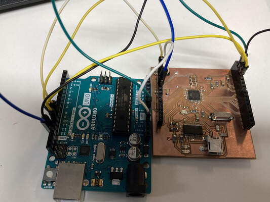
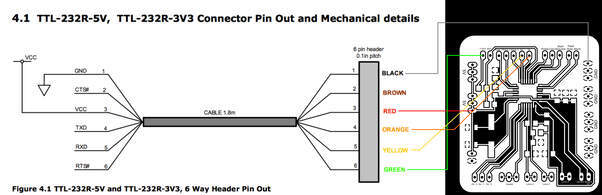
With the arduino bootloader, the microcontroller board can be programmed via the ftdi interface connection. This is done by connecting the VCC, GND, TXD, RXD and DTR pins on the FTDI interface board to the corresponding pins on the controller board. Note that hte TxD and RxD pins have to be swapped, as both the FTDI and control board TxD pins are transmit pins.
Initial testing of the control board was done by loading the Blink example sketch and uploading it to the board. Having successfully done that, it meant that my board was functional.
I think Daniele Ingrassia has done a fantastic job of designing and developing the Satshakit and coming up with so many variations of it. I took a clother look into the CNC version of the Satshakit. However, in using the Satshakit, I became somewhat frustrated because the entire board had only one Vcc and one Gnd pin each - where the power supply was connected. Programming the board was also somewhat frustrating because unlike the regular Arduino Uno, I had to use jumper wires all over the board, both for ISP programming and especially when I wanted to develop code for the board.
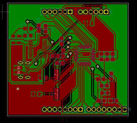
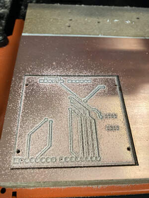
As they say, necessity is the mother of invention - so I decided to complete my own ATmega328 board, something that I started a few months back, but didn't get around to completing, because It took me a while how the FTDI chip works I have also made some changes to my original board layout, such that the traces are mostly 90 degree and minimising the number of 45 deg traces. I have also replaced the normal PTH round pads with longpads for easier soldering.
as the board will also have to match with a girbl boar that will be mounted on top of it, I needed to have 1.5mm outside diameter vias all over the pinouts. However, this were very close to each other and has caused so much failed trials.
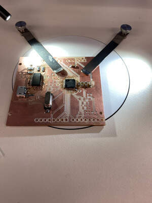
I stuffed and burned the Arduino bootloader into my Fabkit controller board, following the same procedure that I adopted for the Satshakit, which I have described above, but via the ISP header instead. I subsequently tested Fabkit programming it using the FTDI USB-TTL adapter and verified that the board worked as designed. I can't wait to test out my board on other projects :)
BOM
In case you need to order the components, here is the BOM I created for it (the links point to the Finish Digikey website, and the price is in €, but it should be easy to find the right components from your vendor by checking the Digikey website). Each kit should cost € 13.11 (plus the FR1 board... and your time):
Download BOM:
Downloads
The cad models and design files can be downloaded using the links below.
- Fusion 360, full mechanical assembly
- STL files for X and Z-axis assembly.Holders and attachments.
- Additional frame support. Coreldraw file for laser cutting
- Y-axis base plate & stepper motor support plates. DXF file for laser cutting
- KiCAD files for Satshakit serial modified to use FT232RL-REEL UART.
- KiCAD files for CNC Shield to drive DRV8825 drivers.
- Gerber file CNC Shield.
- Coppercam files for the mother board.