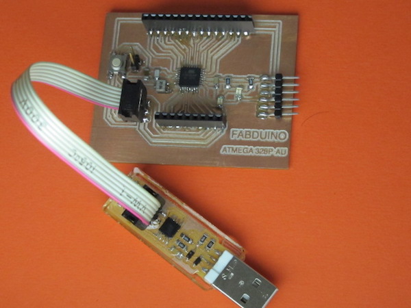
Since this weeks assignment includes me to work with a board I
designed, I decided to build Satsha kit. The following is the
schematic I made based on
Daniele Ingrassia's
work.

I also referred Rahul's documentation of satsha kit, he
informed me of his challenges, so I added a couple of pins for
vcc and gnd; added pins for ftdi as well. Routing was getting
challenging, so I deleted the Rx, Tx on the FTDI that helped me
to route successfully manually.


Milling Satsha Kit
I exported the board trace and cut outline for the Fabduino
board I created.


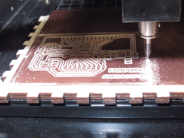
I used the fab modules to mill my design. Following are the
screenshots I took when initiating the milling and cutting.
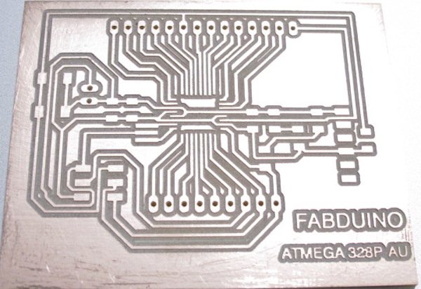
MILLED BOARDS
Traces width: 0.4064
PNG file border: 0.8 mm

After milling and cutting out the board,
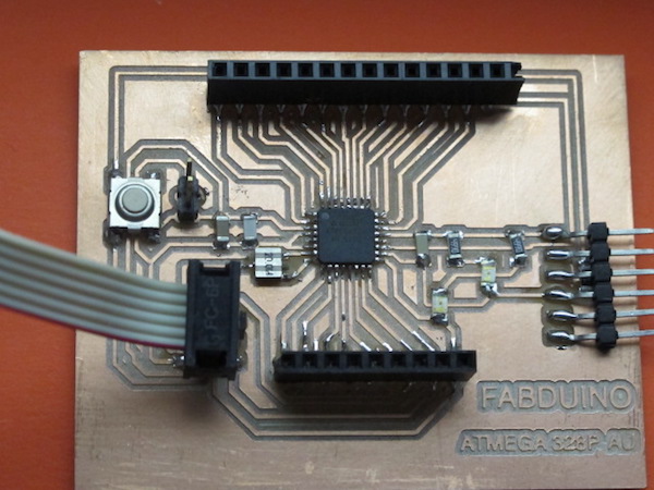
Assembling the board
After collecting the components,
COMPONENTS USED:
1 x ATMEGA 328
1 x 3X2 PIN HEADER (ARVISP SMD)
2 X 2X2 PIN HEADER SMD
1 X FTDI HEADER SMD
1 x 10k Ohm RESISTOR RES-US1206FAB
2X 499 Ohm RESISTOR RES-US1206FAB
1 x CAPACITOR 1 uf
1 x CAPACITOR 10 uf
1 x CAPACITOR 100 Pf
1 X 20MHZ RESONATOR
1 x SWITCH
2 X LED
Soldering was challenging as the traces were small and so
close, and but was able to get it all assembled neatly.
Programming on Satsha kit
To start programming on Satsha kit, I used my fabISP to burn
the bootloader, which can be done on Arduino IDE itself. You
would need to add MiniCore to
board manager.

Then Go to Tools, since my board has an Atmega 328P-AU, I
selected the same, set the external clock to 20MHz and changed
the programmer to USBtinyISP. The rest I made no change and ran
Burn Bootloader.

All the above documentation was from 2019.
This year My final project idea changed to A fabable CNC Machine. I will Still be using very similar approche in designing the motherboard as my main machine controller using Atmega 328p.
However, as I a continuing Student, I was not satisfied with my earlier approach from 2 years ago in regards to the scope of this week.
Individual assignment:
- Add an output device to a microcontroller board you’ve designed,
- Program it to do something
Group assignment:
- Measure the power consumption of an output device
Individual assignment 2021
This week I decided to make DC motor driver using Full-Bridge to control the motor. In my final project I need to control a DC (A spindel motor From Ronald MDX 20 ) as an end effector..
This board was heavily inspired by the DC motor driver board made by our Fab academy instructor Krisjanis. You can read more about the project on Kris's Git repository.
Schematic
In this week, the PCB included some new componnents: Full-Bridge PWM Motor Drivers, Voltage Regulator and DC Power Jack.
- A4953 Full-Bridge DMOS PWM Motor Drivers (Datasheet)

A4953 are designed to operate DC motors. The current from the output full bridge is regulated with pulse width modulated(PWM). Through the function in Full-Bridge the logic current could transform into PWM which are able to simulate the anologe signal by switching digital signal on and off at a fast rate.
The Ronald MDX 20 spindle motor works with 12V and its speed and power decrease with decreasing the input voltage. Normally we would need analog output voltage to control the speed of the motor and we don't have that in the ATtiny412. So here comes the PWM (Pulse Width Modulation) that can generate different voltage levels out of a fixed DC voltage by controlling the frequency of the output pin.
Another important thing to consider is the direction control of the DC motor, as the spinning direction of the DC motor changes with change in polarity of the motor terminals. To do this with software, an H-Bridge is needed which helps in reversing the polarity of the motor. Our instructor Kris has already added the (A4953) in the Kicad library and is part of FabLab inventory.
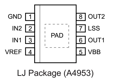
As seen from the above image that I got from the datasheet of the A4953, it has two control pins IN1 & IN2 which are set as OUTPUTs as the motor direction will be as the following:
- Clockwise:
IN1 = HIGH&IN2 = LOW - Anti-Clockwise:
IN1 = LOW&IN2 = HIGH
A 100uF Decoupling Capacitors is used to stablize the voltage.


Voltage Regulator as explained in the introduction video for Input Devices Week by our instructor Kris Getting Started with Input Devices. was used to maintain a 5V operating voltage for Attiny 412 at the same time driving a 12V DC motor. (Datasheet)
Coding
What I am doing in the code is created two funcions Forward and Reverse to rotate the motor gradually up to full speed and decrease to 0 speed by changing the analogWrite of IN1 and IN2 pins. The Forward and Reverse could refer to PWM Control Truth Table from Full-Bridge datasheet.

#define motorIN1 0 // IN1
#define motorIN2 1 // IN2

void setup() {
  // initialize digital pin LED_BUILTIN as an output.
  pinMode(motorIN1, OUTPUT); //In hole
  pinMode(motorIN2, OUTPUT); //Out hole
}

// the loop function runs over and over again forever
void loop() {
  Forward();
  Reverse();
}

void Forward(){

    digitalWrite(motorIN2, 0);
//  digitalWrite(motorIN1, 1); testing
//  delay(5000);

  for (int i=0; i<256 ; i++)
  {
    analogWrite(motorIN1,i);
    delay(30);
  }

  for (int i=255; i>=0 ; i--)
  {
    analogWrite(motorIN1,i);
    delay(30);
  }

  digitalWrite(motorIN1, 1); //break
  digitalWrite(motorIN2, 1); //break
  delay(100);

  digitalWrite(motorIN1, 0); //standby
  digitalWrite(motorIN2, 0); //standby
  delay(100);
}

void Reverse(){
  digitalWrite(motorIN1, 0);

  for (int i=0; i<256 ; i++)
  {
    analogWrite(motorIN2,i);
    delay(30);
  }

  for (int i=255; i>=0 ; i--)
  {
    analogWrite(motorIN2,i);
    delay(30);
  }

  digitalWrite(motorIN1, 1); //break
  digitalWrite(motorIN2, 1); //break
  delay(100);

  digitalWrite(motorIN1, 0); //standby
  digitalWrite(motorIN2, 0); //standby
  delay(100);
}
The functioning motors demonstration
This is the video showing how the DC motor responds with the PMW code inputfrom the Code and also able to change Direction.Challenge Faced
Uploading the Programe to my board, and connecting the power supply, it was supposed to spin the Dc Motor and turn it off after 5 seconds. The program was uploaded well, but there was no Spinning. After several checks I realized that I had not connected one LSS pin on the A4952 driver to the ground as indicated in the datasheet. So I soldered a jumper from that pin to ground and my program worked as it should. On the second iteeration i fixxed the issue on my kicad schematic and soldered a new board.
Group assignment
The aim this week was to measure the power consumption of an output device. we check the Brushless Motor From Kitja's output device with Kitja and Ranjit and concluded that as a set input voltage of 9V and the motor starts rotating with minimum value of input current 0.04Amps when the speed value increases current demand also increases. The maximum value of current is when motor rotating with value at current value of 0.8...Please see more detail at my collegues website Group assignment.
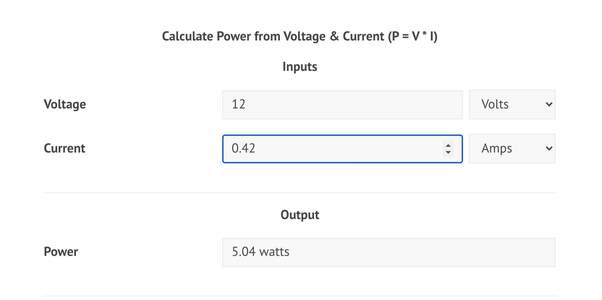
To measure the power consumption of my Spindle motor I connected the power supplier in the lab and provided 12 volt as I am running the motor at full speed. I then noted that the Current that the spindle drows at max. Speed was 0.42 Amps. Please notice that this maght varry once the Spindle is mounted on the CNC machine and actually cutting as the spindle will be exposed to torque from the chip load of the material it will be cutting. But as it stands, I used OnLine power Calculator.
then concluded the Max Power consumption of this device on this setup to be 5.04 Watts
Download
Design Files - Eagle File (for the 2018 project)Board Trace (2018)- Board Trace(2018)
Board cutout(2018)- Board cutout(2018)
The Kicad zip file A4953 (2021)
