ATTINY 412 & BLDC MOTOR & ESC 30A
For work with ATTINY 412 is needed:
For Power LED is needed:
For ESC 30A connection is needed:
Component below is not needed (but that I understood after I drew schematic part):
MY OWN ELECTRONIC DESIGN | KICAD SOFTWARE
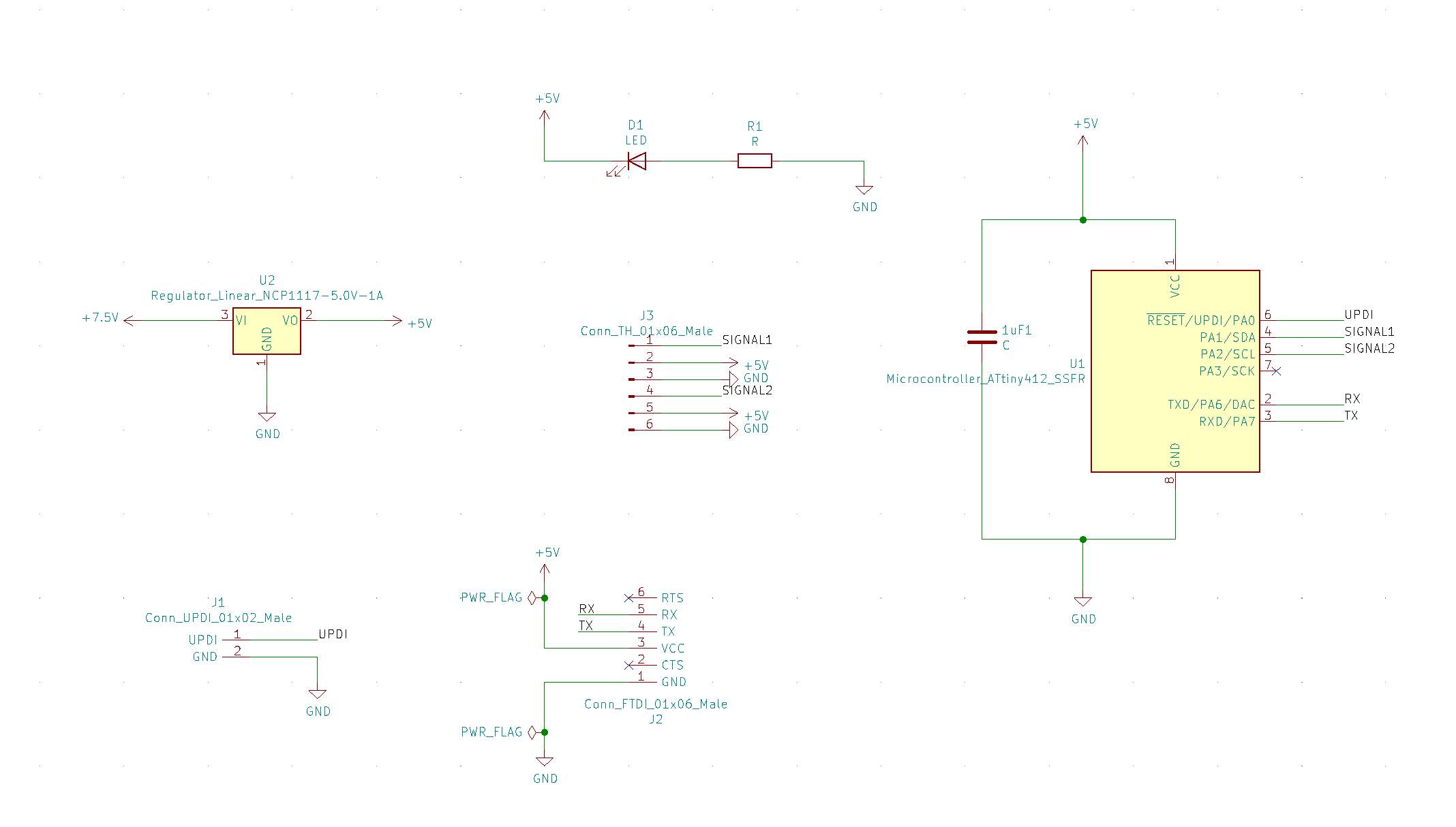
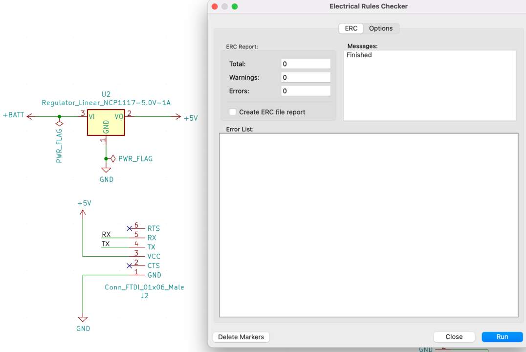
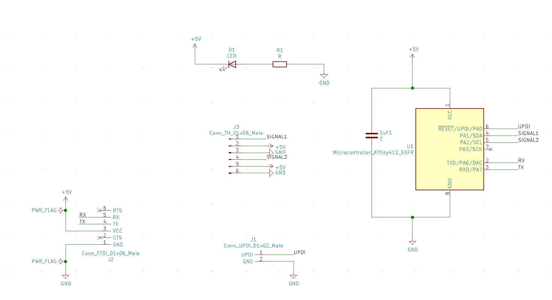
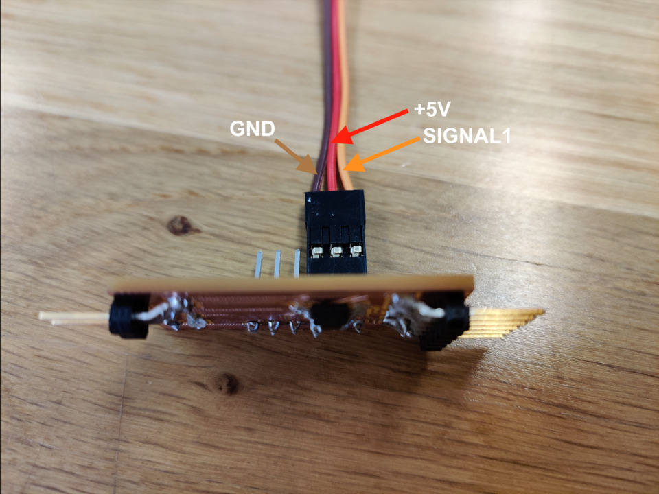
- I was able to create schematic part thanks to the work of previous weeks - Electronics design and Input Devices. New thing was that I needed to understand which pins I need to connect ESC30A wires - there are SIGNAL,(needs to be with PWM functionality, PWM symbol is "~" in the SpenceKonde schematic) +5V and GND. As I plan to test two motors I added through holes with 6 holes to later add 2 x ESC30A (for each need three servo connectors). Explanation of what is what I learned from HowToMechatronics and as in previous weeks from SpenceKonde.
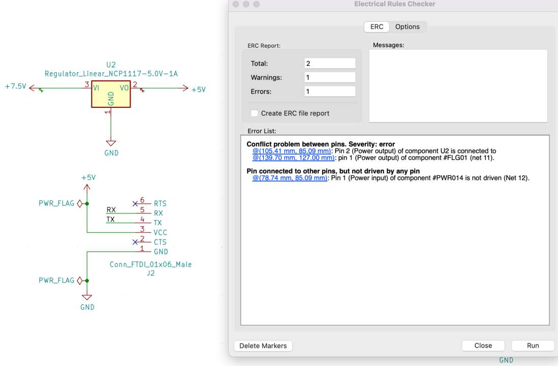
- Then I clicked on the Perform electrical rules check button in order to check the electrical rules. I received a message about a conflict problem between pins. The problem was that I had identified PWR_FLAG a not right energy source.
- Then as always (non)funniest part - to draw connection lines and of course in the final step when I tried to connect all GND in some places connection lines stuck. Then I tried to create GND as Filled zones (how: look at the previous week).
- ❗And then I realized that I hadn't read the ESC30A datasheet well enough, it says that "It has separate voltage regulator for the microcontroller for providing good anti-jamming capability". This means that no additional regulator is needed in my scheme. Final version of schema looks like that:
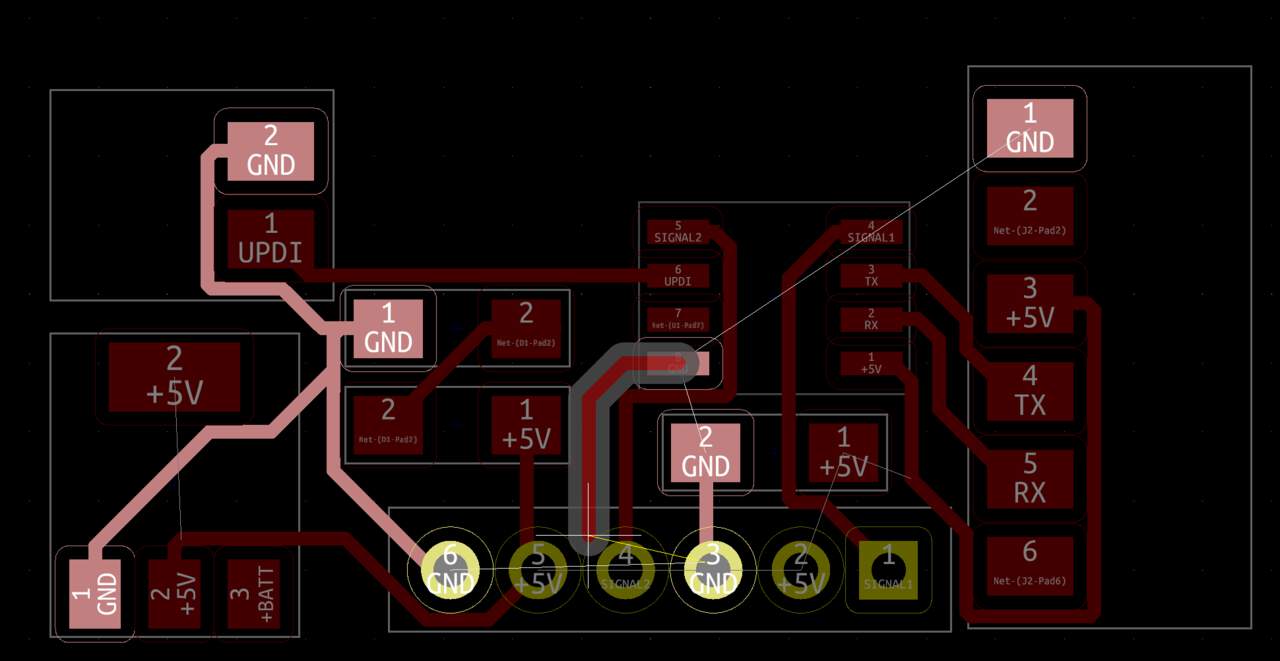
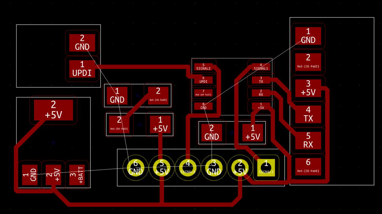
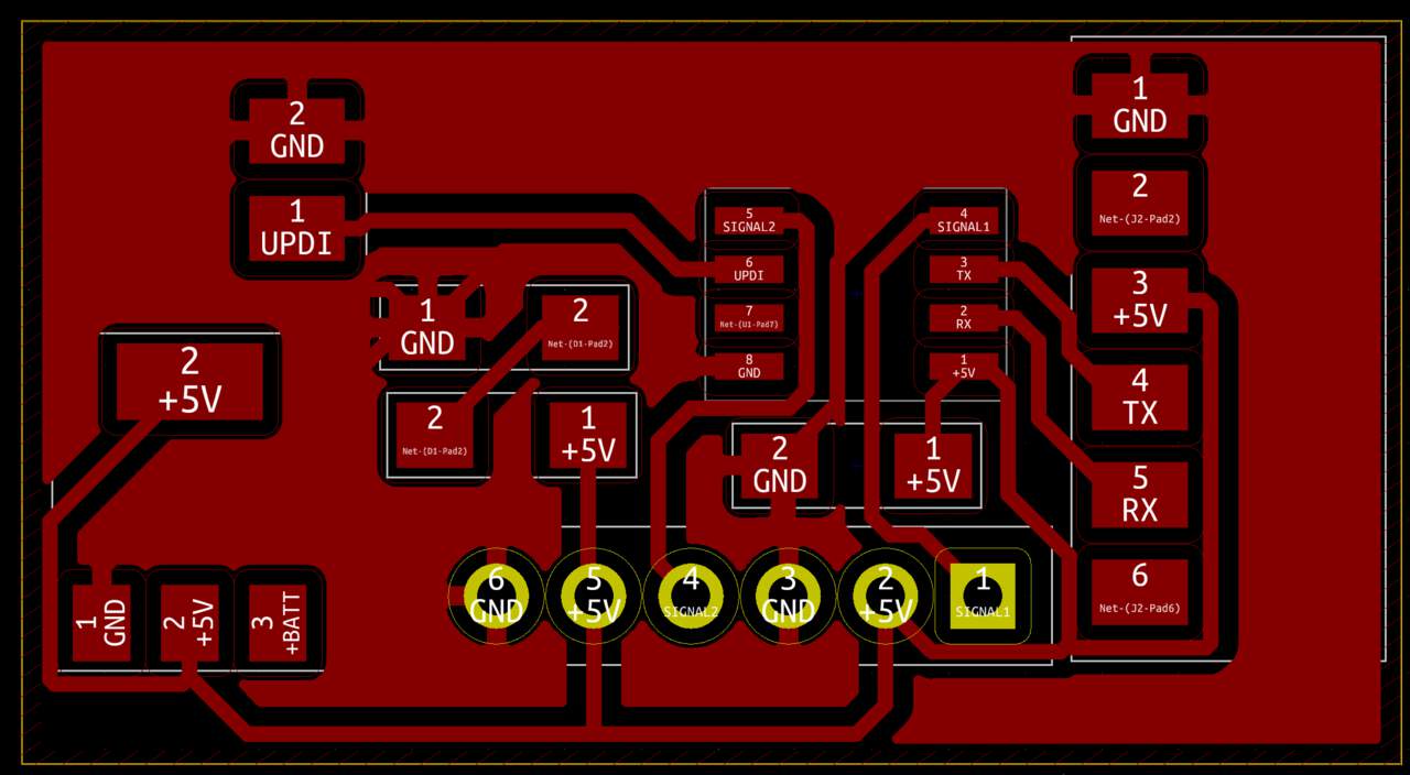
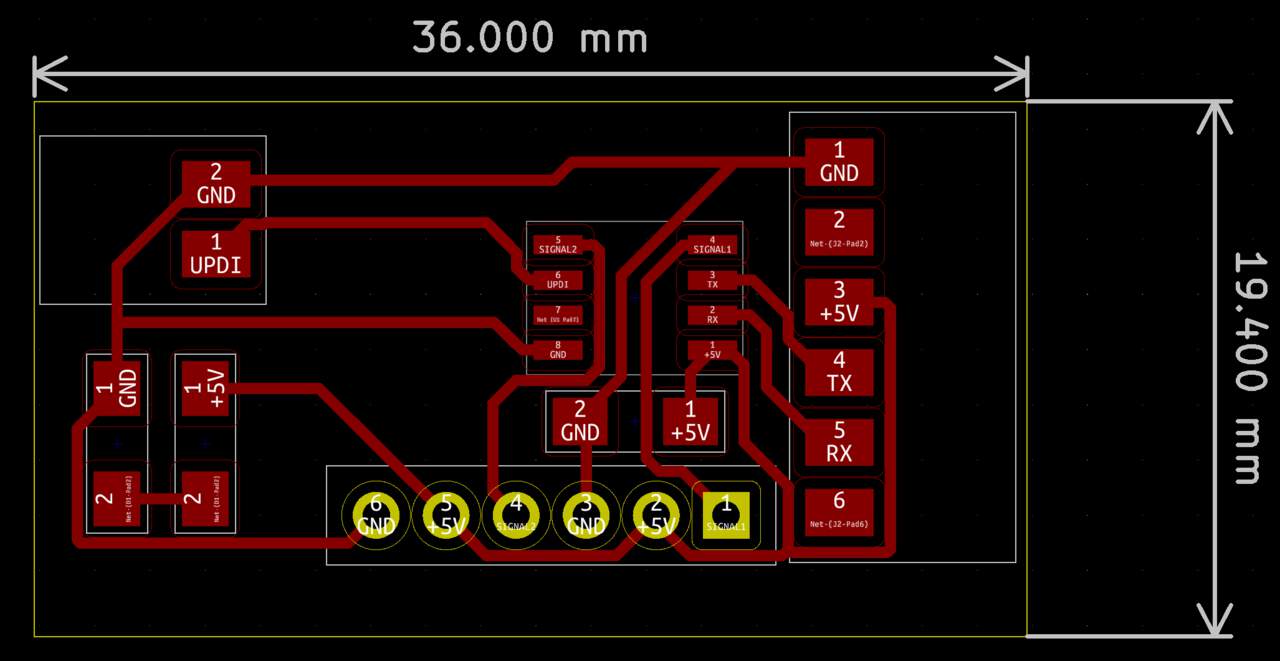
- Since I knew the new way of generating files for the milling process with CopperCam I plotted gerber and generated drill files. At this step my instructor Kris said that CopperCam will work more faster if I don't use GND as Filled zones but just connection lines. As I understood that I didn't need a regulator now I have more spaces - I (re)design and made GND connection lines.
PCB MILLING & SOLDERING PROCESSES
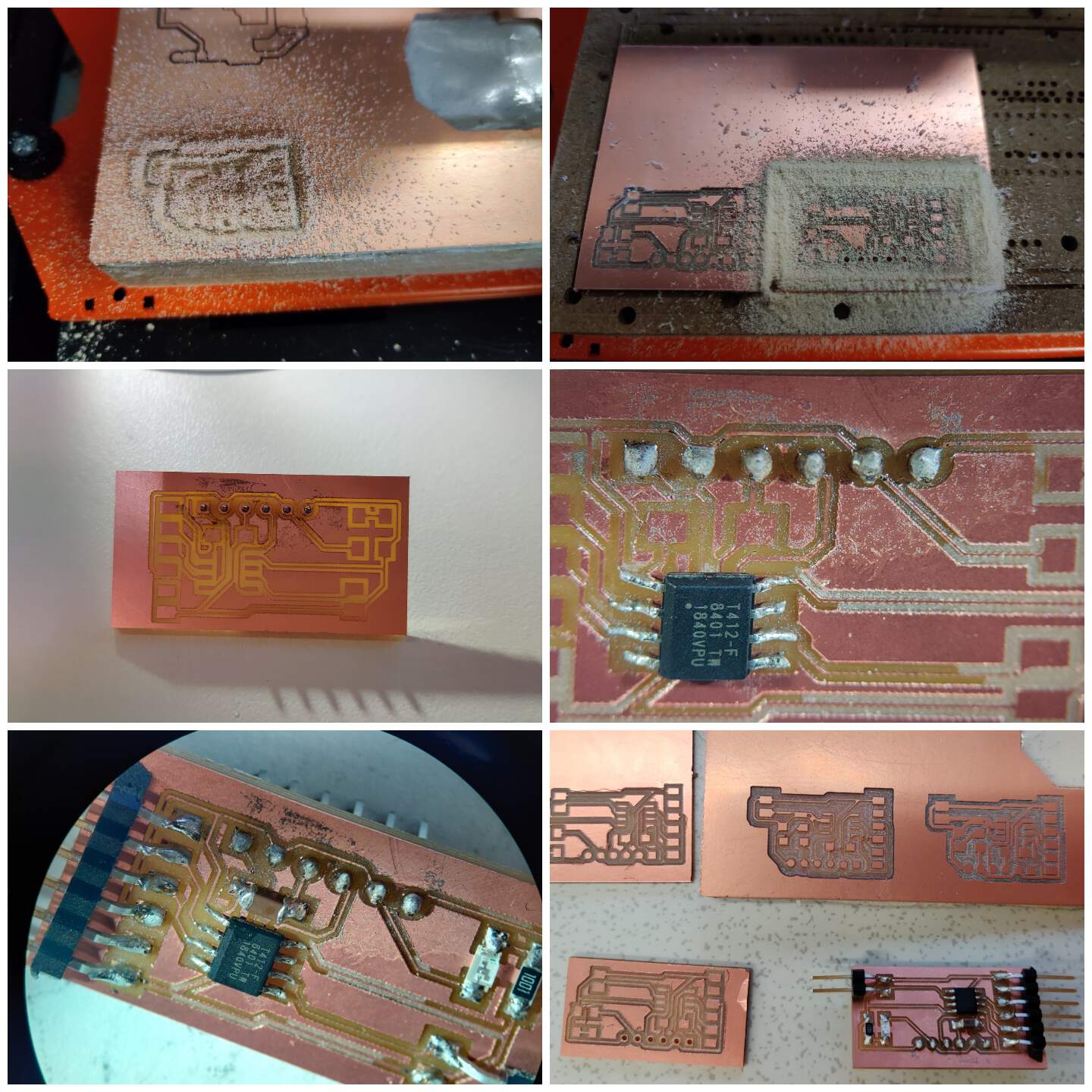
- I invested almost all Sunday for the milling process because many times the milling result wasn't so good - the copper had come off the tracks or cut too deep and just later under microscope I saw that tool was broken - this explains why the result was different each time without changing the settings. I changed the tool and tried again - received better result but still not the best - I checked continuity of traces and as all needed connections worked I tried to solder that PCB.
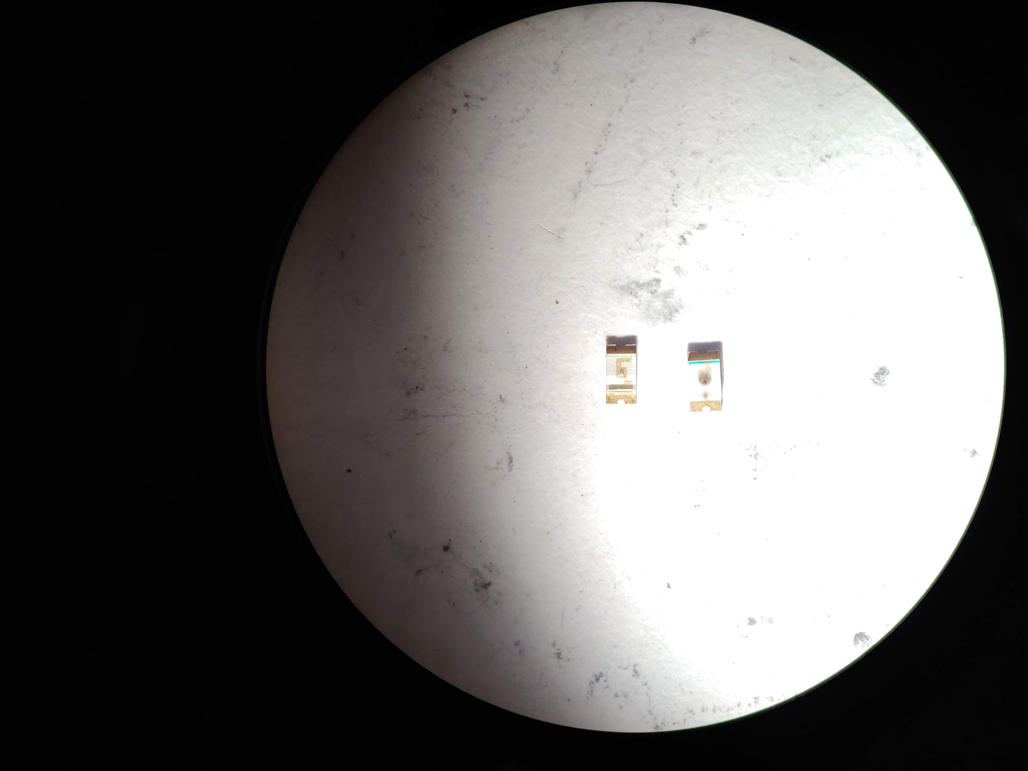
- 🔥 I learned something I should have known theoretically. Checking the right direction of the LED to know how to solder it I used a power supply and as I knew that my board would work with 5V - I also indicated the voltage as 5V. During the test - I heard "puf-puf" - my LED burned out. Now I know why this happened - not for nothing that the LED on my board has a resistor - it reduces 5V coming on the board to the required LED. Another benefit - I compared my burnt to a new LED under a microscope and \ in the future it will be easier for me to determine what a burnt LED looks like.
ASSEMBLING PROCESS
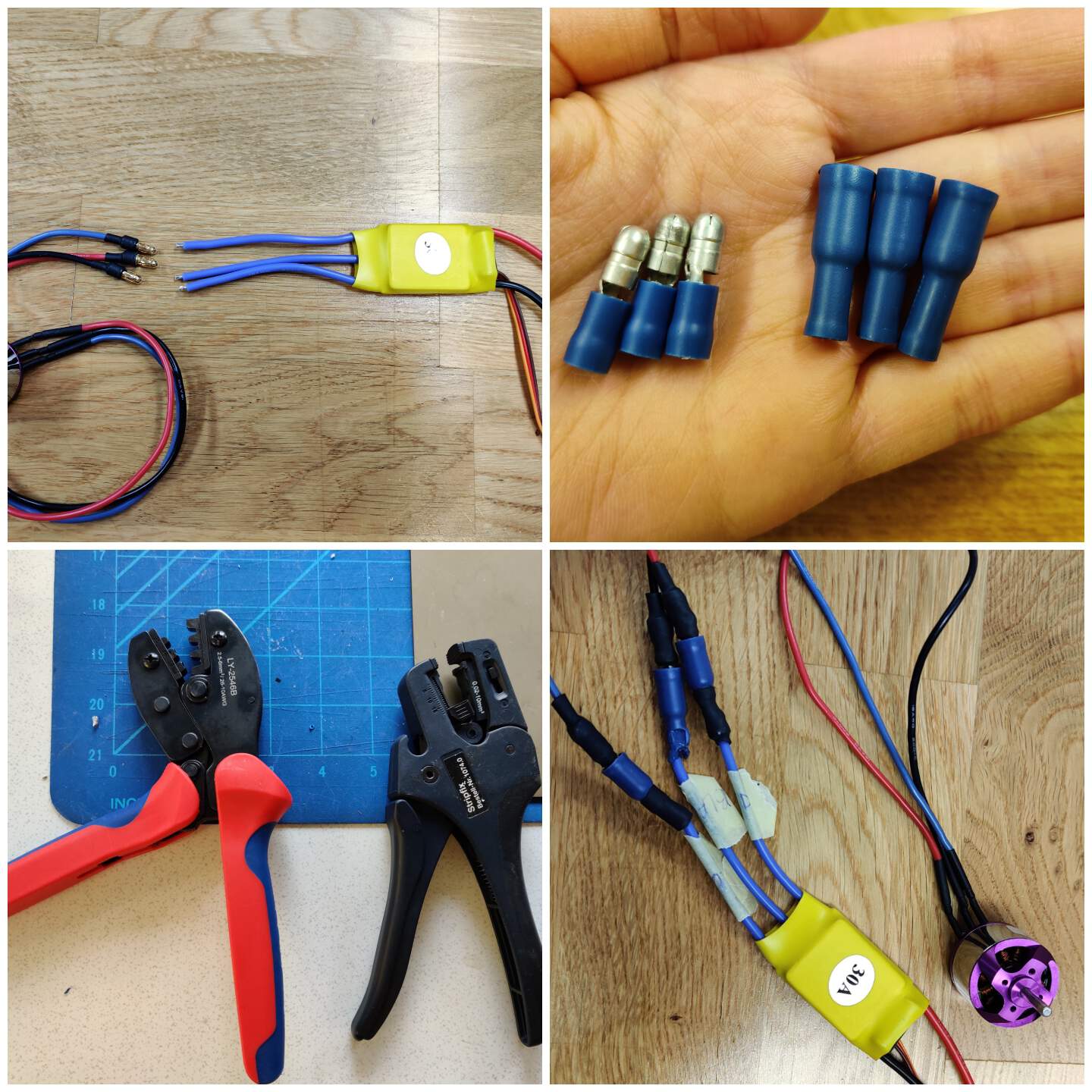
- I didn't have the right bullet connectors for connecting BLDC motor and ESC 30A but in the laboratory I found something useful and I tried connect in that way.
To connect in the right way ESC 30A and my PCB board I several times checked my schema and wires meanings.
And before making a Power supply connection is necessary be sure that settings are right - I turn ON it and in my case is possible set Voltage from 7.4V to 14.8V.
PWM FUNCIONALITY
- PWM - Pulse Width modulation it's a simple but intelligent way to control digital signals that we use to vary the energy that is sent a load. PWM is a type of signal. The PWM signal has only two states that's why you can represent binary data with the signal. 0 and 1 or low and high. The frequency of a PWM signal must be constant as well as the duration of each pulse. Pulses are generated at high frequency and by varying the time of each pulse the average voltage at the output can be controlled. For example, I know that ESC needs voltage from 7.4V to 14.8V - let's choose 14.8 V. This volt pulse is 50% time low and the other 50% high, then the average voltage is 7.4 V - half the voltage, and so we can change the average voltage at the output by only changing the time of the pulsations to control the brushless motor. If you are wondering why we are not using a variable resistor to control the energy that is sent to a load, something like a potentiometer that can stand a lot of power. Because using a resistor is not the most efficient way to control energy. Much of energy is lost in the form of heat when passing through the resistance and when dealing with high power loads such as motors it is simply useless. The use of PWM is the most efficient way of using energy saving considerably more than other methods very important if your system uses batteries. (clarity in my head helped introduce the Youtube tutorial). PWM functionality is expressed through ESC. Exactly ESC will also be programmed, then it is important to specify the min / max pulse width and as I found in technology enthusiast forums (reference missing), need 1000 - 2000 interval in microseconds. These values are specified in the attach() function of the Arduino Servo library to control the signal. Servo have to receive high-pulse control signals at regular intervals to keep turning. If the signal stops, so does the servo (in my case - brushless motor).
- More about ATtiny & Arduino IDE pinouts relationship look at Embedded Programming week.
PROGRAMMING PROCESS
- First of all I programmed a Communication test to be sure that chip works.
This video not included in GIT, because size of it is more than allows also after video optimization.
- Then I tried to make a program which generates random speed number from 0 to 180 but it didn't work. I am not sure why but it could be related with that in next steps I need calibrating ESC 30A because now it doesn't know what is the min and max value.
            #include Servo.h
            Servo ESC;
                void setup() {
                  pinMode(2, OUTPUT);
                  ESC.attach(2,1000,2000);
                }
                void loop() {
                    ESC.write(random(0,180));
            #include Servo.h

                Servo ESC;     // create servo object to control the ESC
                void setup() {
                  pinMode(2, OUTPUT);
                  // Attach the ESC on pin 2
                  ESC.attach(2,1000,2000); // (pin, min pulse width, max pulse width in microseconds)
                  Serial.begin(115200);
                  Serial.println("Initializing...");
                  delay(1000);
                }
                void loop() {
                  for(int i=0; i<180; i++){
                    ESC.write(i);
                    Serial.print("Speed: ");
                    Serial.println(i);
                    delay(100);
                  }
                  delay(1000);
                }
"HERO SHOT" VIDEO - RESULT
This video not included in GIT, because size of it is more than allows also after video optimization.
GROUP ASSIGNMENT
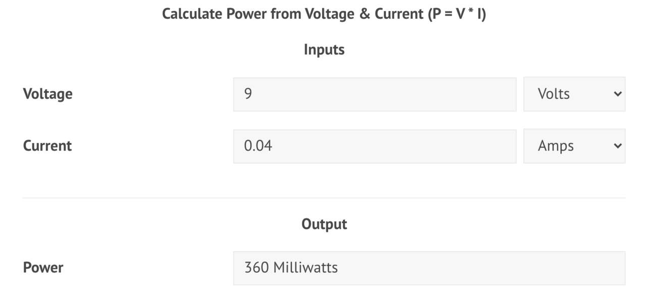
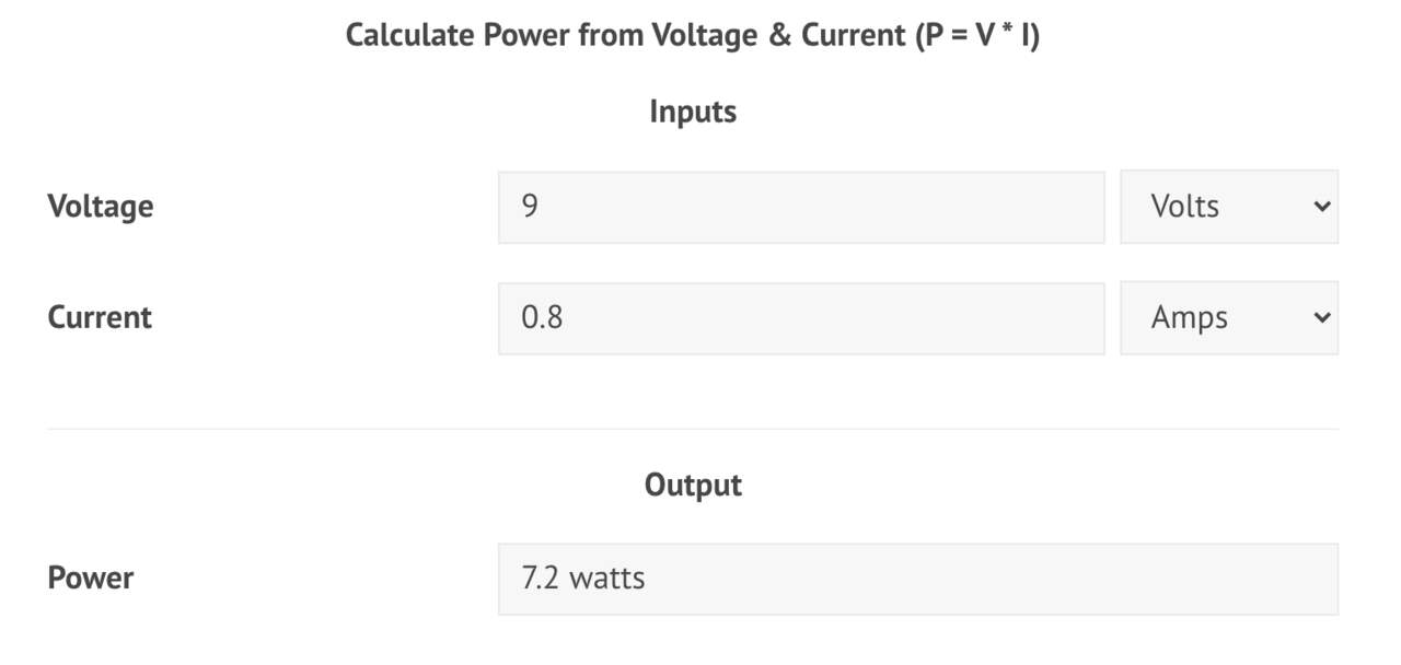
- For this week group assignment is measuring the power of an output device. As my group mates Solomon and Ranjit still work with their output devices we check the result of my motor. We concluded that when we set voltage as 9V and the motor starts rotating with minimum value - 20, current is 0.04 when values increase current also increases. The maximum value of current is when motor rotating with value 180 and current is 0.8.
- Then in online calculator we calculated power in minimumam and in maximum situations.