SETTING UP UPDI PROGRAMMING TOOLKIT WITH ARDUINO, MEGATINYCORE & PYUPDI
- As you always need to test your board you need a toolkit or development environment to do that.
- Downloading the latest version of Arduino. Downloaded ZIP files extract and put it in the Applications folder.
- Usually when you program your boards you need to choose the programmer and the board. In the default Arduino installation
you don't have any ATtiny chips and this is reason why you need to install an add-on which called MegaTiny Core and
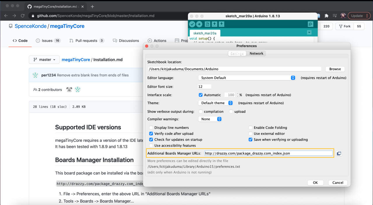
in order to install that - find github repository megatinycore (by SpenceKonde) and from Installation page copy boards manager URL:
http://drazzy.com/package_drazzy.com_index.json
and copy it in Arduino Preferences - Additional Boards Manager URLs. - Then go to Tools-Boards Manager, it will load the lists and you should be able to find megaTinyCore, then hit install.
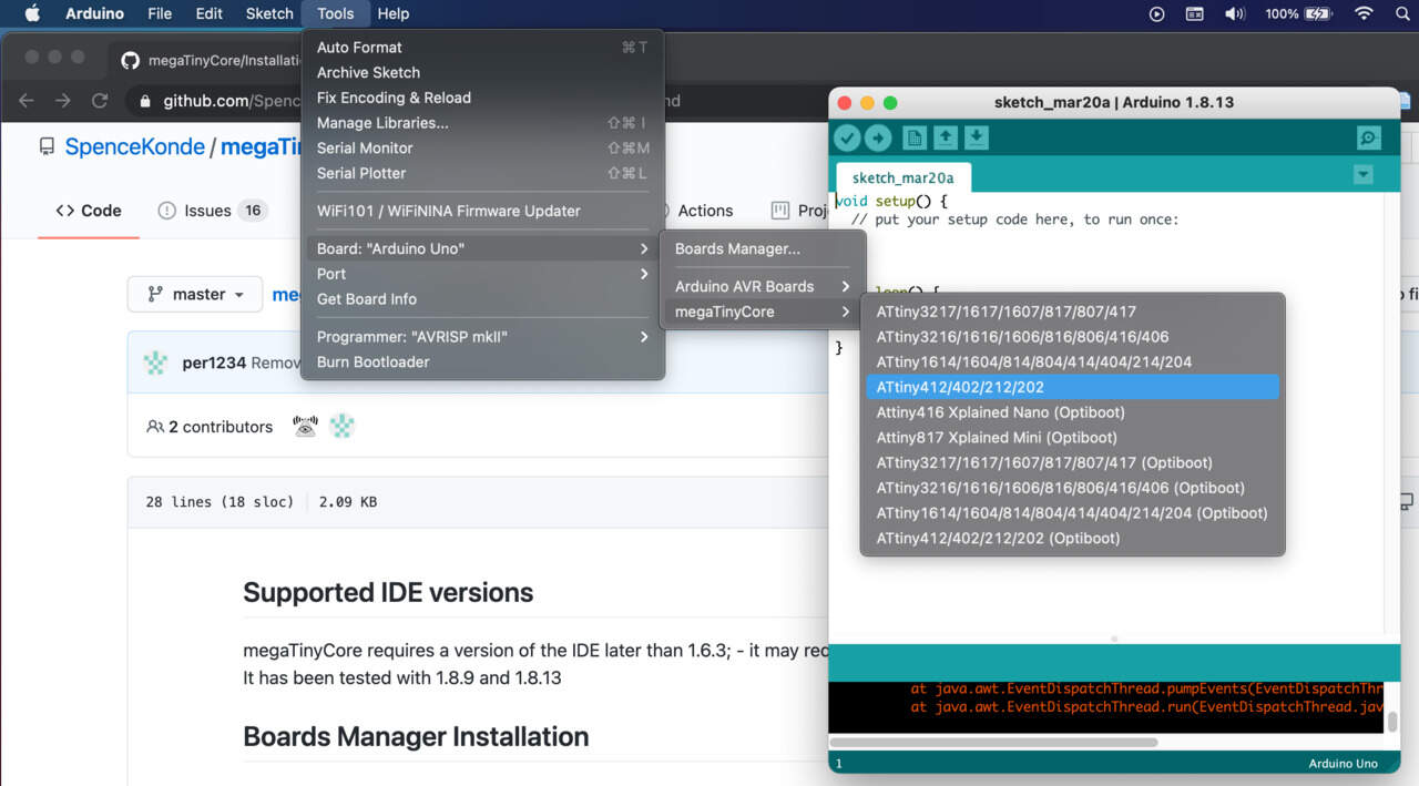
- Go to Tools - Board and now you can see all these ATtiny chips. In my case I choose ATtiny412/[..]. Also make sure that Clock Speed is 20 MHz. Check that in Chip:ATtiny412 was selected as an ATtiny412 chip.
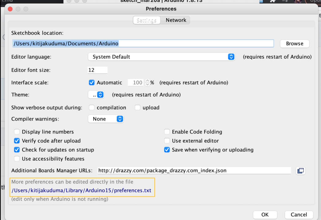
- Arduino IDE needs to be used for compile code and then another tool which is called pyupdi in order to upload it to the board, but in order to be able to find the compiled files you will need to edit configuration file. Go to Arduino Preferences and there should be a link to the preferences file. To edit this file, close Arduino software.
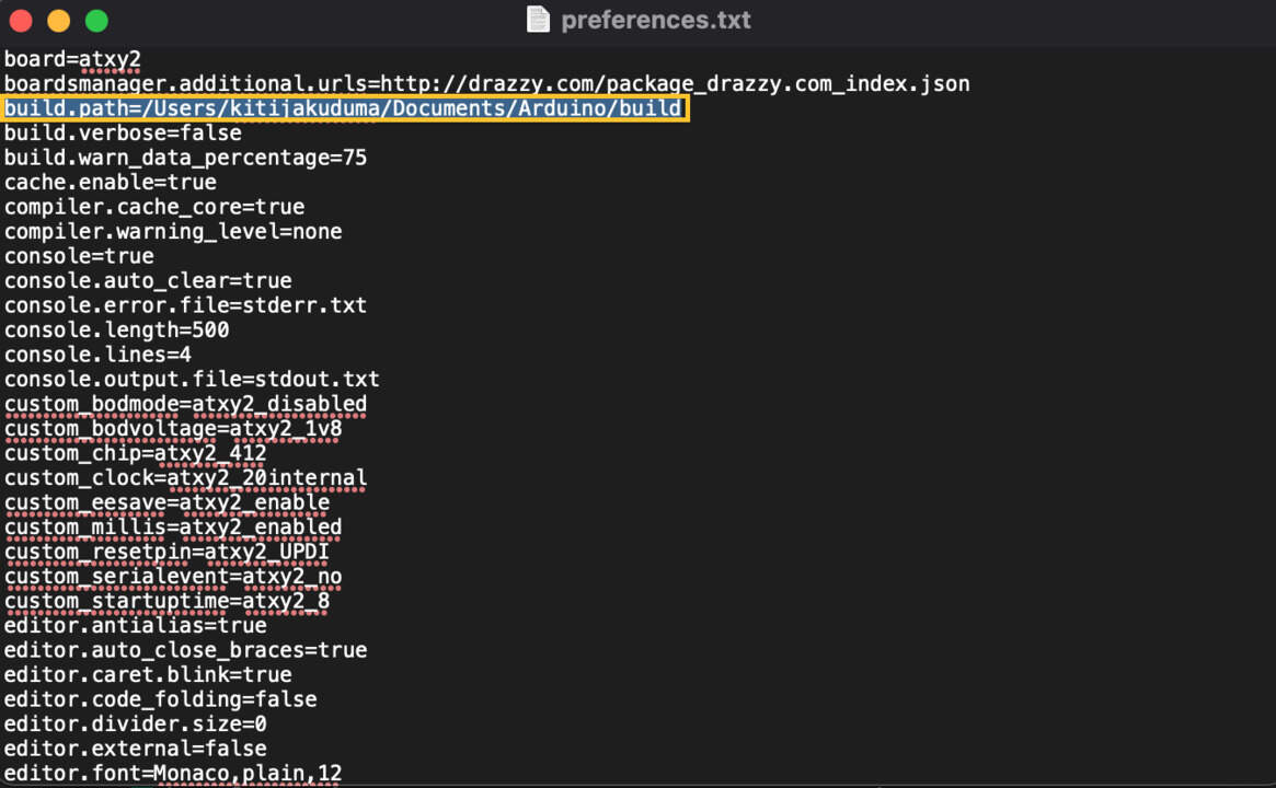
- Open preferences.txt and what you need to add is build path like this command line
build.path=[HomeDirectory]/[WhereYourArduinoFilesLive]/Arduino/build
in my case -
build.path=/Users/kitijakuduma/Documents/Arduino/build, then save the file and open Terminal. - When in Mac I try to use ls, mkdir, sudo etc. commands I receive message Operation not permitted for that I need to change Mac System Preferences.
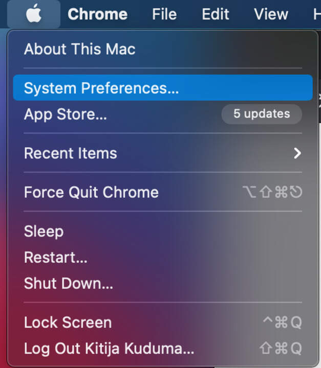
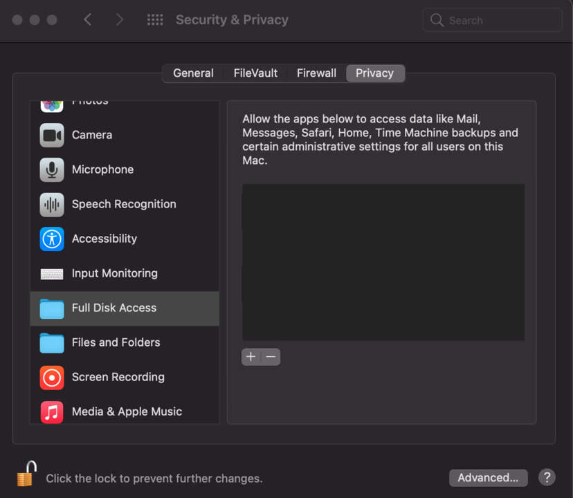
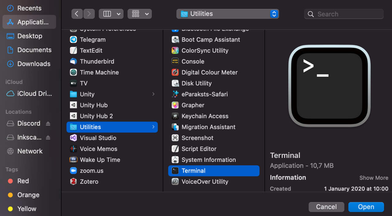
- Pull down the Apple menu and choose System Preferences, then choose Security & Privacy control panel. Then select the Privacy tab and from the left side menu select Full Disk Access. Click the lock icon and authenticate with an admin level login. After that click on the + (plus) button to add Terminal application with full disk access. Navigate to the Utilities folder and choose Terminal application. Click Open.
- Relaunch Terminal and look how you can't find the error message Operation not permitted.
For fix this issue I follow instructions step by step from osxdaily.com cd Documents/Arduinols[you see that there isn't build folder]mkdir buildls[now you can see that build folder was built- Now open Arduino IDE and put some example code, then compile it, make sure that you see the Done compiling message.
- Go to Documents-build and you will see there is a file [filename].ino.hex and this is thhe file that actually needs to upload to the board.
HOW DO YOU DO IT? - You need to find the github repository pyupdi (by mraardvark), download the ZIP file and put it in the same folder where Arduino lives. In my case - Documents folder.
- Then go back to the Terminal and go to this pyupdi folder with
cdcommand - Try to run it with
./pyupdi.pycommand. It's gonna tell you that Python3 isn't there, for that you need to install Python3. - ❗ I have Python2, one option could be uninstall it and install Python3, but you agree with me that notice by Stackoverflow if you do something wrong "you may break your whole operating system" is enough reason to try ignore the fact that I have Python2? How do I do that? Just before all commands add python3. Seems simple, right? This simple discovery took me a long time.
.. BUT BEFORE OPEN TERMINAL - EXPLANATION OF PROBLEM 1 AND HOW I FIXED IT!
.. FIXED! NOW YOU IT'S TIME TO OPEN THE TERMINAL
INSTALL PYTHON 3, WORK WITH PYUPDI
brew install python3
❗ Remember, for this step you need install homebrew before. Homebrew is a package manager for Mac OS.- After installation validate that you installed it by
python3 --version - In order to install package manager for Python pip3 you need to run
brew postinstall python3. You need pip3 in order to install dependencies for pyupdi package. postinstallcommand doesn't work, I received Warning: The post-install step did not complete successfully. Then I try to install in another way (following by ahmadawais.com), first of all try commandsudo curl https://bootstrap.pypa.io/get-pip.py -o get-pip.pythenpython get-pip.pybut this command doesn't work, then I triedsudo python get-pip.py- also it doesn't work, thenpython3 get-pip.py- and this works!- After installation go to the pyupdi folder with
cdcommand. - Then again try to run
python3 ./pyupdi.pycommand. You see a message - No module named 'serial'. - But in this folder is also requirements.txt file what usually in Python solutions is where the dependencies lives.
- You can use command in order to see what are these dependencies -
cat requirements.txt. pip3 install -r requirements.txt.- After that if you try to run
python3 ./pyupdi.py- it shows what is possible with it. - Type
python3 ./pyupdi.py -hand you can see a bit more details about what you should specify in order to upload things to the board. - First specify the type which defines by -d - all things that it is capable of programming and in my case especially - tiny412. Next thing is going to be the baudrate which is defined by -b - 19200. Then you will need comport - which is defined by -c and will basically deport your programmer.
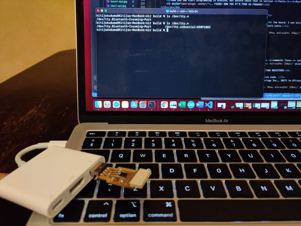
- Open another Terminal window and you need a list of the serial devices that are connected to the computer at the moment for that type
ls /dev/tty.*and connect your FTDI - this is what you need for comport. - Next is flash which defines -f - there copy path to build folder, then add a slash and then just copy .ino.hex file name. Then add -v in order
to make it verbose. The result of all these text paragraph is following command line:
python3 ./pyupdi.py -d tiny412 -b 19200 -c /dev/tty.usbserial-D30725LE -f /Users/kitijakuduma/Documents/Arduino/build/412blink.ino.hex -v - Then hit enter, but it receives the message "Exception: UPDI initialisation failed". It's because the board isn't connected to the UPDI port. Connect and then run the command again.
- Failed again!? Yes, in my case! Smells like an issue! Biggest challenge is that I don't know if that problem is in my board on the computer. 🇱🇻 Latvians have an expression "Morning is smarter than evening!" and as I am Latvian woman I went to sleep and will try to find a solution in the morning!
- Four weeks ago I made my board and when I check functionality it worked, of course I didn't believe that something now don't work, because with my eyes I see that everything is fine and
weird is in fact that when I use
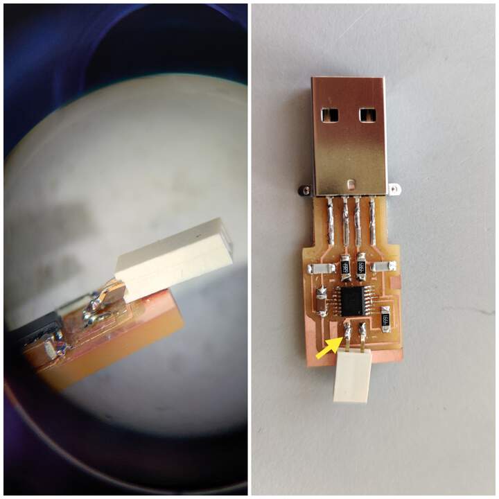
ls /dev/tty.*to check which devices are connected to the computer, it recognizes it! Then I understood that all is good with the USB connection part, but it can't recognize UPDI connection and then in FabLab I looked in microscope (only in FabAcademy I appreciate how useful it is) and I found, I found, I found! One part of UPDI is unsoldering - it is in air, it doesn't connect to traces. - Then I tried to run my board again and now it works! How can I know that? Because now I receive message Programming successful.
- Now you can start programming in Arduino, but before checking that in section Tools-Port and select number of your UPDI.
EXPLANATION OF PROBLEM 2 AND HOW I FIXED IT!
.. FIXED! NOW IT'S TIME TO GO FORWARD!
EXPLANATION OF PROBLEM 3 AND HOW I FIXED IT!
.. FIXED! NOW YOU IT'S TIME GO FORWARD!
USE OFICIAL FTDI CABLE OR MAKE BY SELF
- To see the result of your program you need an FTDI cable which gives power for the board. I was excited about the fact that with my previous FabAcademy weeks knowledge and skills I can make the same functionality cable by self! It would be interesting to compare costs.
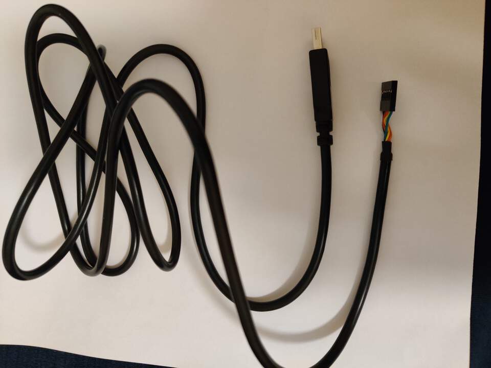
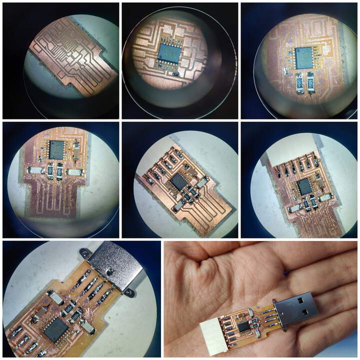
- Functionality of both are the same!
| Component | Costs |
|---|---|
| Chip FT230XS | ~2,14 $ |
| Capacitors 2 x 10pF | ~0,20 $ |
| Capacitor 1 x 1uF | ~0,10 $ |
| Resistors 2 x 49 | ~0,88 $ |
| Female connector (number 6) | ~0,20 $ |
| Mini USB connector | ~2,26 $ |
| Totaly: | ~5,78 $ (If oficial FTDI cable cost ~21,25$ then make by self is more cheaper and feeling of satisfaction are guaranteed) |
CLASSIC ARDUINO PROGRAMS
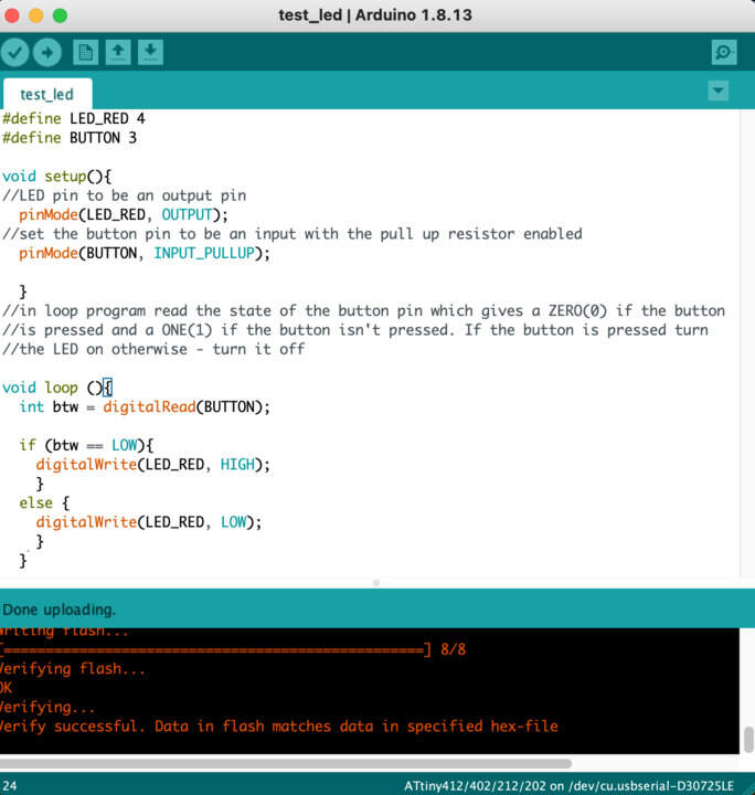
- Below you can see my program code which a little bit more I explain in comments lines but idea of program is when you press button, red led start to blink.
- Then I updated my program code including two LEDS and an activate button.
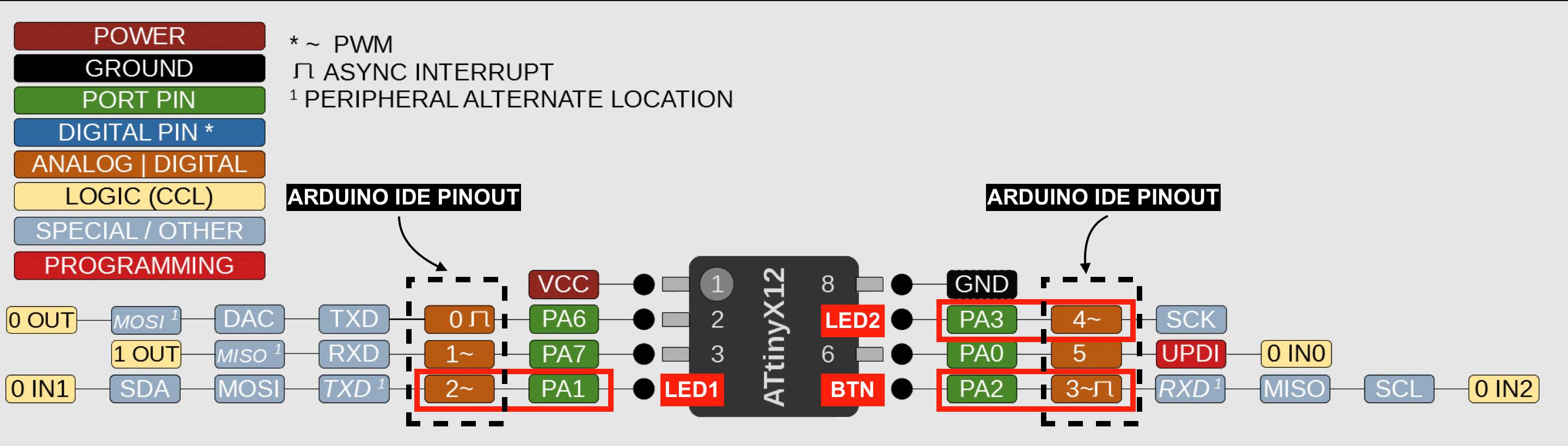
ATTINY412 & ARDUINO IDE PINOUTS RELATIONSHIP
- For understanding microcontroller pins, I used SpenceKonde. It should be remembered that the numbering of the microcontroller is different from that assigned to the variable in the Arduino. The numbers in orange color are those to be indicated on the Arduino.
"HERO SHOT" VIDEO
- Now I download the Neil Gershenfeld program to test serial connection also. The purpose of this is to test that when you send messages to the board and if the board's gonna give information back. For that it is needed to know that TX and RX are connected to PA6, PA7 pins and those you need for serial communication by Arduino.
TRY TO PROGRAMMING IN LANGUAGE C & GNU AVR Toolchain
- Year after year C is the most popular programming language. In TIOBE TOP100 I read that lowest position since 2001 for C was #2 in April, 2020 - yap, really low!
- But seriously where is the secret because C rarely is convenient? What is common to FORMULA1 drivers and programmers? Yes, they like speed! In this case C is like the formula's car, because it works faster than other programming languages.
- First of all I need to install GNU AVR Toolchain.
brew install avr-gcc- To check that it installed I type
avr-gcc --version - I wrote the simplest which is possible to upload to the board - just for testing.
int main(void){return 0;} - For compiling I use AVR. Go to the Terminal with
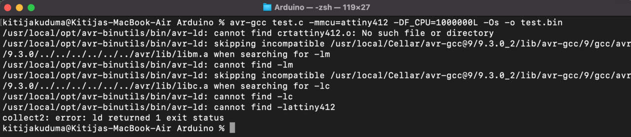
cdcommand go to the folder where the file is saved. Then try compile it with command line
avr-gcc test.c -mmcu=attiny412 -DF_CPU=1000000L -Os -o test.bin, but I received many errors (look at below). -DF_CPU- is the definition for speed which by default is 1 MHz. It's necessary if you use delay functions. For the test program it's not so important.Os- it's to optimize the size and output file is going to be called test.bin.- As I watched tutorial by Zero Amps who use ATtiny10 just for be sure where is the problem I try to replace command line
-mmcu=attiny412to-mmcu=attiny10and I checked the directory - it's compiled! - As I didn't find a solution for this, I skipped this step and went forward to see what was gonna happen!
- For upload file to the board I use
avrdude -vutility, but of course I received an error: Command not found: avrdude brew install avrdudeand now it's in my computer!avrdude -c usbasp -p attiny412 -U test.bin, but I received a list of valid parts and ATtiny412 I didn't find. I am sure that it is related to the previous step when I compiled the file, but as I didn't find a solution quickly for this, I skipped the next steps.- ❗ When I went back to Arduino and again try upload previous program in my board - it didn't work! This is reason why I uninstalled avrdude with command line
brew remove avrdude
TRY TO PROGRAMMING IN LANGUAGE PYTHON in VISUAL STUDIO CODE
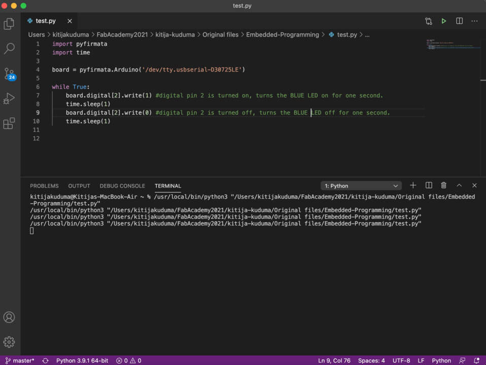
- Open VS Code, click on the Extensions and type python. Then click Install to download it. Then you will typically need to close out VS Code and reopen it in order to activate Python extension. Now it's time to start writing in Python.
- As I read on the Internet that for programming to board with Python, it's necessary to install Firmata. How wrote Fab Academy student Yazan Barhoush that this protocol can be used to control the board.
- For that I install it in Terminal with command
pip3 install pyfirmata
❗Reminder that I use pip3 not pip because I have python2 & python3 in computer. - Then in VS Code I wrote the program followed by Fab Academy student documentation, but I didn't receive any warning or error message but also at the same time the board didn't work.
THEORY ABOUT C + PYTHON = CYTHON
- As I haven't more time to understand how it works in practice, below I left some quotes for self don't forget learn more about it later
- First of all don't try to find it in TOP 100 - stable releases came just in 2020.
- It's important to understand why so often C compared with Python, these programming languages always at the top.
- (by educba) The main difference between C and Python is that, C is a structure oriented programming language while Python is an object oriented programming language. In general, C is used for developing hardware operable applications, and python is used as a general purpose programming language. C language is run under a compiler, python on the other hand is run under an interpreter. Python has fully formed built-in and pre-defined library functions, but C has only few built-in functions. Python is easy to learn and implement, whereas C needs deeper understanding to program and implement.
- (by IDG TECHtalk) As many Python users know that Python is convenient, but not always fast, but C on the other hand is fast but rarely convenient. Cython lets you get the best of both. Cython provides a custom set of type annotations and syntax elements that extend Python and allow it to be compiled to high performance C.
NOT A CLASSIC PR0GRAM OR HOW TO MANIPULATING REGISTERS
- This is about how to manipulate registers rather than relying on Arduino code.
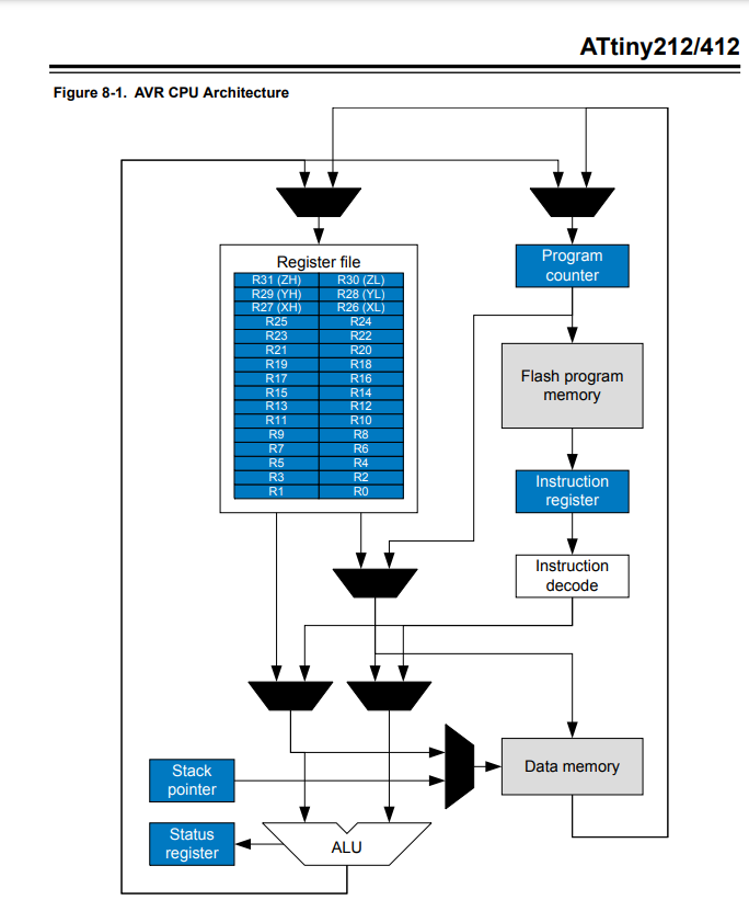
- To answer what is registers I read Datasheet (by Microchip Technology Inc., 2017) to ATtiny412. Answer I try to find in AVR CPU - Architecture. At first moment for me this block diagram was nice, but I understand .. nothing!
- Block diagram showing how the main processor is configured. The ALU (Arithmetic Logic Unit) is responsible for performing calculations like addition, subtraction, bitwise logical operations etc. Data can come from or be stored 32 general-purpose registers each holding 8 bits (or 1 byte). You are able to read and write to many but not all of these registers directly from code. Other registers exist like Instruction register or within Data memory space which are divided into I/O registers to assist with pin control.
- ATtiny has SRAM data memory, EEPROM data memory, and Flash program memory. The first is flash program memory - here lives your code. When you write code it is compiled into machine code and stored here. Next is SRAM which is static random-access memory. Registers have function registers also. To write to a special function register you need to first find its address in SRAM and then specify what value you want to write to it in the program. The rest of the SRAM is used to hold values for things like variables when you define them in code.
- Note that when you power down or reset microchip the SRAM is cleared.
- And finally EEPROM (Electrically erasable programmable read-only memory) it's often not considered part of the memory of the processor since it's usually on a separate bus. It also has much slower read and write time but it's useful for storing data that needs to be saved between resets or when power is lost.
- I watched a video by SparkFun Electronics and at the beginning thought that I will also try to build my program code with use registers, but actually I needed more time to understand that clearly.
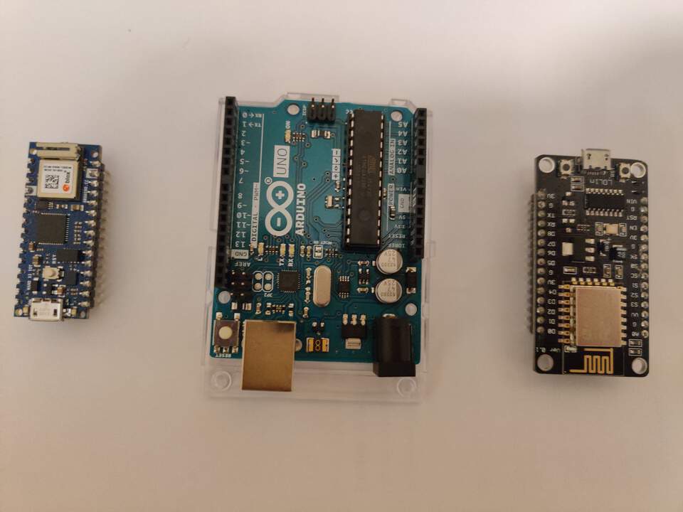
STORAGE BOX FOR ELECTRONICS MODULES
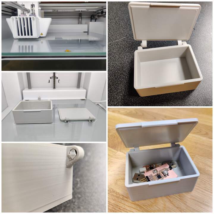
- As now I have three electronics modules I needed to start thinking about how to store them, because now I carry them in my wallet and there is a risk of them breaking. For solution I printed my storage box with Ultimaker S3+. Challenge was in the fact that I can't push the lid in the box. What was the solution? FORCE (Instructor Kris not mine)!
GROUP ASSIGNMENT
This week I also work together with Solomon and Ranjit.
ARDUINO NANO 33 VS ARDUINO UNO R3 VS LiLon NodeMCU V3
- Chip: ATSAMD21 vs ATmega328P vs ESP8266
- Flash memory: 256 KB vs 32 KB vs 32 KB instruction, 80 KB user data
Explanation of ESP8266 is interesting, actually we don't understand which of this would be flash memory, maybe user data, because how I knew after I read Datasheet in flash memory lives code. - SRAM memory: 32 KB vs 2 KB vs < 50 KB (when ESP8266 is working under Station mode, the max programmable space accessible is around 50)
- Digital Pinout: 14 vs 20 vs 17
- Analog Pinout: 8 vs 6 vs 1 (The ESP8266 only supports analog reading in one GPIO. That GPIO is called ADC0)
- NANO also has Wi-Fi and BLE 4.2 connectivity, but if you aren't so strong in electronics then all upper technical specifications couldn't give very good opinion of these boards, but what others tell about it? About NANO we can read that it is small, powerful, efficient & IoT connected, but UNO is the most popular Arduino board. A perfect choice for those starting out. But if compared with LiLon NodeMCU V3 then it has smoother LED fading and more precise motor speed control.
- We chose ESP8266 to test how it needed connect to Arduino software.
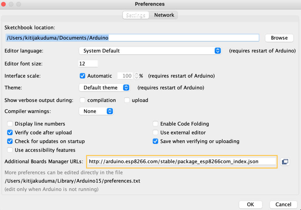
- First of all we needed to selecting Tools menu, then Boards - Boards Manager. And like in individual part install an add-on. In order to install that - find
github repository esp8266 (by d-a-v) and from Installing with Boards Manager section copy boards manager URLS:
https://arduino.esp8266.com/stable/package_esp8266com_index.json
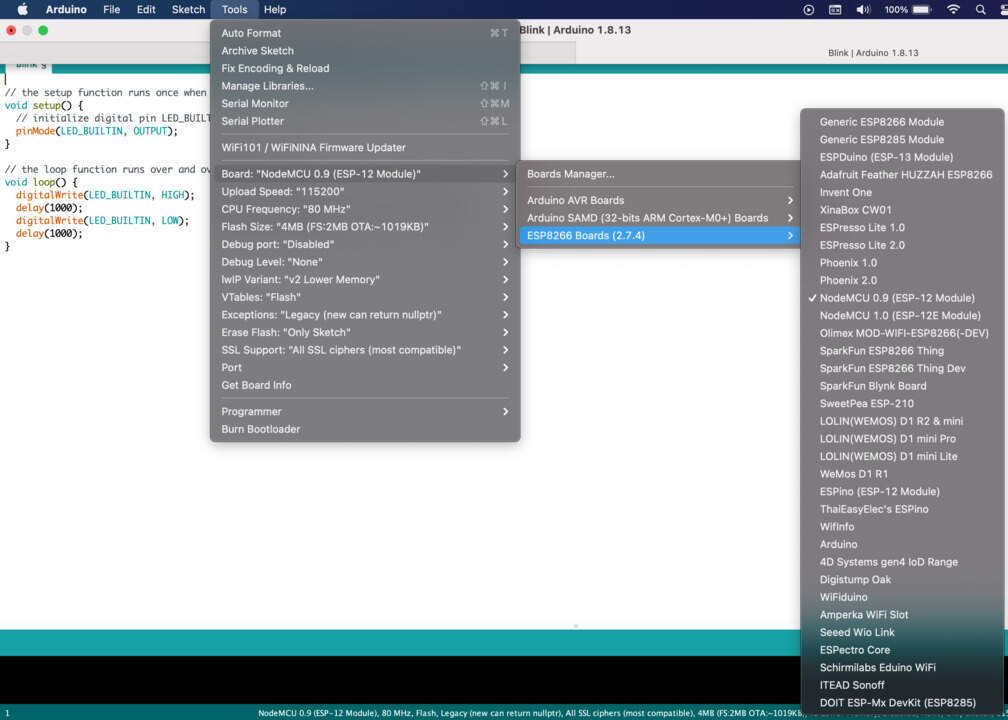
and copy it in Arduino Preferences - Additional Boards Manager URLs - Then go to Tools-Boards Manager, it will load the lists and you should be able to find esp8266, then hit install.
- Go to Tools - Board and now you can see all these esp8266 boards (2.7.4) chips. In this case we choose NodeMCU 0.9 (ESP-12 Module).
- When it's done final step is Select a port.