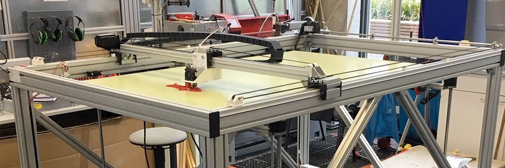
Big 3D-Printer
With a maximum volume of 150 x 90 x80 cm
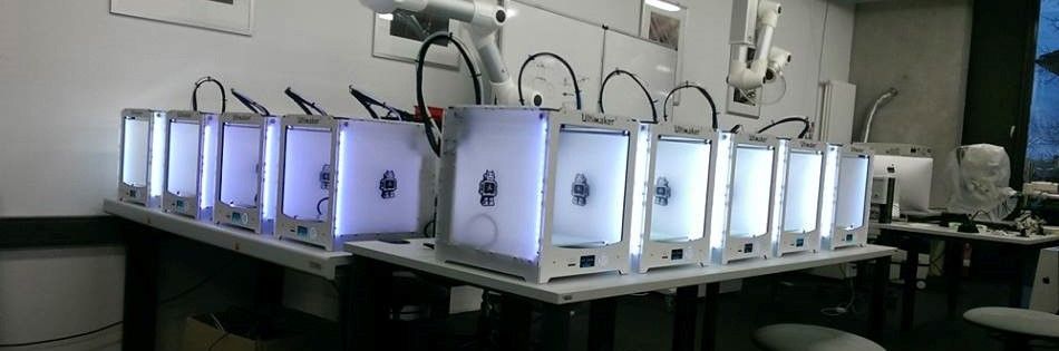
Some of our Ultimaker
We´ve got more than 25 3D-Printer of diffrent types
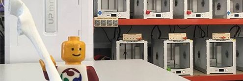
Greeting
Our best employee in HRW FabLab
Assignment 9:
Molding and Casting
Task:
- review the safety data sheets for each of your molding and casting materials, then make and compare test casts with each of them (group project)
- design a 3D mold around the stock and tooling that you'll be using, machine it, and use it to cast parts
Work
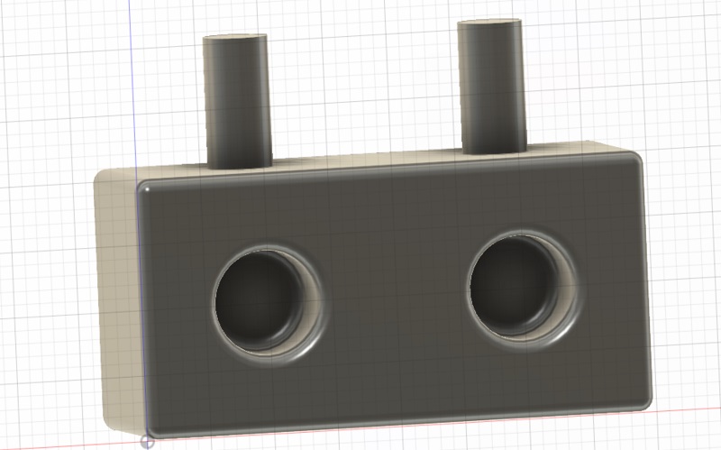
The big advantage of molding and casting is to produce a lot of identical parts with one form. So I wanted to design a casting part which makes sense in a bigger number. In addition I wanted to create a way to connect the single party with each other. So I tried to generate my own LEGO-Brick. Again I used Fusion 360 cause there is a CAM tool integrated. See the final design below: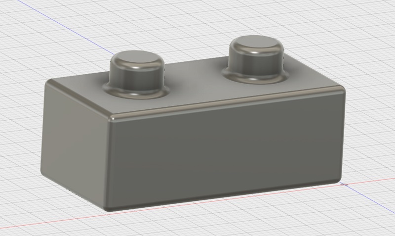
In the next step I added the parts where I can infill the form. Here you see the bottom of the brick and the filler tubes:
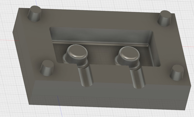
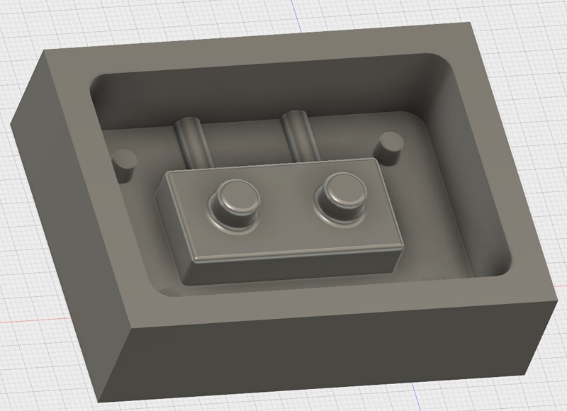
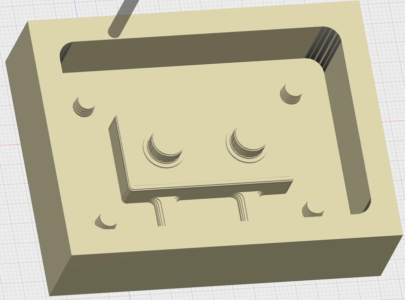
Now I had to generate a negative from my brick. That is a quite simple step in Fusion. Just generate a cube around the brick and subtract the brick from the cube. Finally separate the cube in two parts and you get the casting form below. There is a top and a bottom part. I added also four pins to connect the two parts with each other. That is what my casting form will look like:
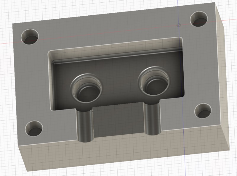
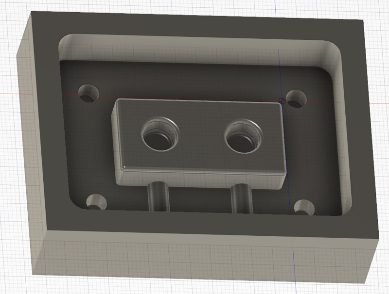
Because of we also want to cast the casting form I had to generate again a negative form of the negative form. The process is equal with the first negative. After this step I got my model for the 3d milling process:
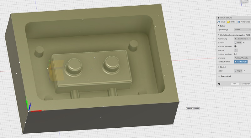
The next step is to generate the milling code. Therefore fusion 360 has ja CAM process included. Just chose the part you want to produce and click at the “CAM” process icon. The first step is always to generate a setup where you declare the settings of the process. So for example where the starting point is and in which direction the single axis are. You also set the area you want to cut.
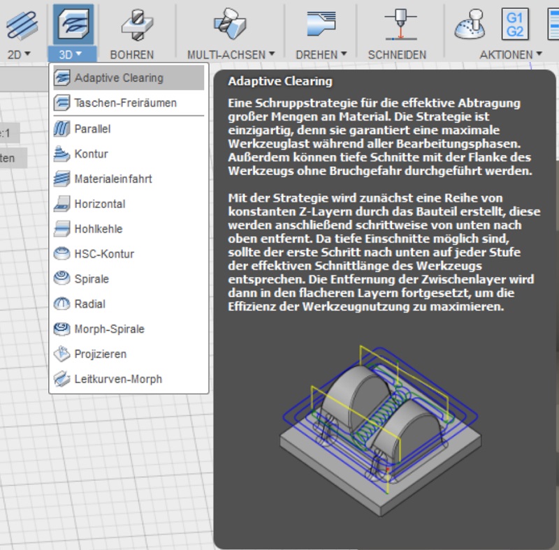
After finishing the setup there are a lot of different types of milling processes. Which one is the best depends on the geometry of the part you want to mill. Often you need more than one step to get the bets result. I started with the adaptive clearing process because it is a good option to remove a lot of material. The finishing follows in a second step.
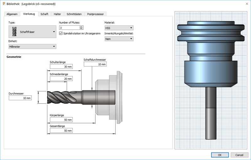
Now you have to insert the setting of the process to for example which tool you use. There are a lot of tools in the library but because I used a unknown milling machine I had to create a new tool for the library. You have to add a new tool and then describe it with a lot of dimensions and extra info. Therefore I had to measure the necessary dimensions directly at my milling machine. See below the surface of the tool adding process.
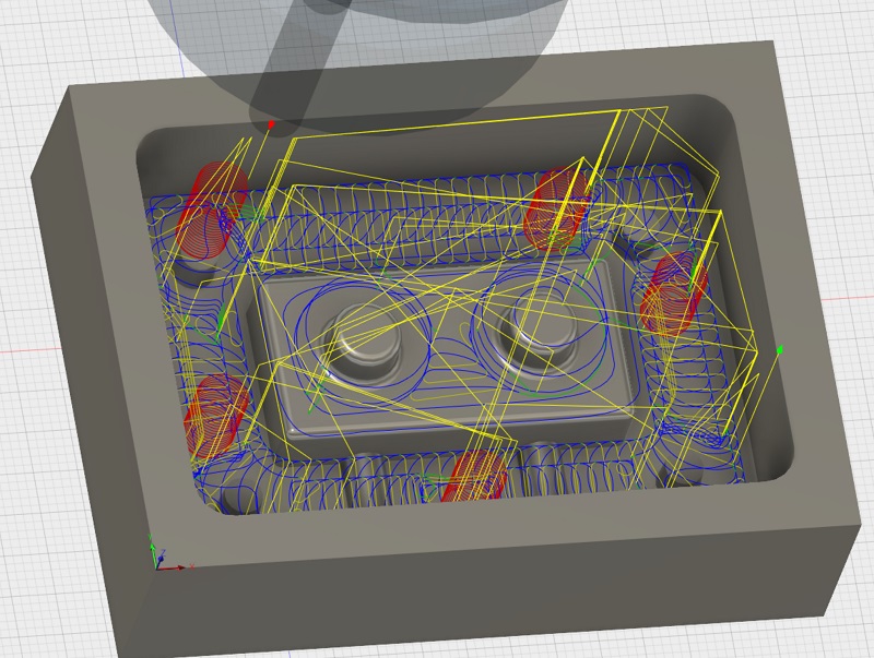
After I insert a few more settings to the adaptive clearing process like the maximum of tolerance fusion 360 automatically generate the toolpath. I didn´t changed the milling parameters at all because we used a quite simple to cut wax which didn´t need a optimization of the parameters. Also a had the option to control the speed later during the milling process manually. The red lines are the small spirals during a drilling process. The yellow lines are the ways without real contact with the workpiece and the blue lines are the path of the milling process. See below the first clearing process:
In Fusion you also can simulate the milling process like a video. Here you can find problems during the process and also see what is the result.
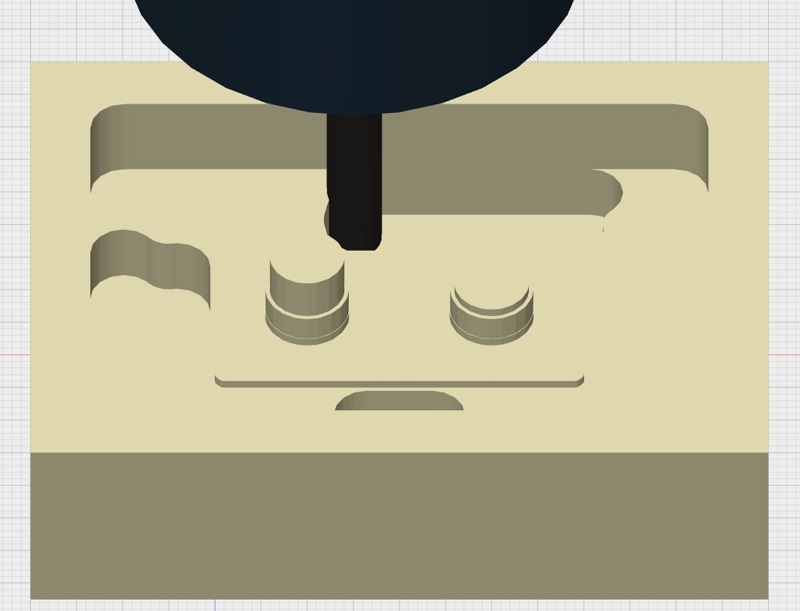
See below the workpiece after the adaptive clearing process and a shadow of the geometry I want to generate. As you see there is a lot of material left because I wanted to use a big 6mm milling tool for the first step to remove a lot of material. I also generated a offset of 0.5mm to finish the complete surface in the next step with the 3mm tool.
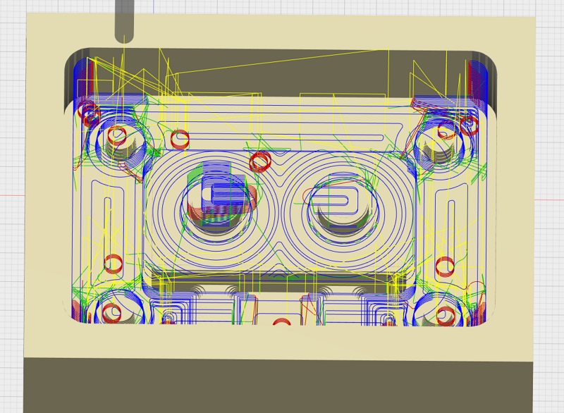
For the finishing I added a new 3mm tool and chose the “contour” process. This process allows to optimize the cliffy surfaces of my model and removes the missing corners. See the toolpath below:
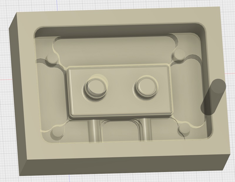
I minimized the tolerance to 0.05 and the maximum input depth to 0.1 mm to get the following result. I thought that this result looks good enough and I renounced a third milling process because they would need a lot of time without making the result that much better.
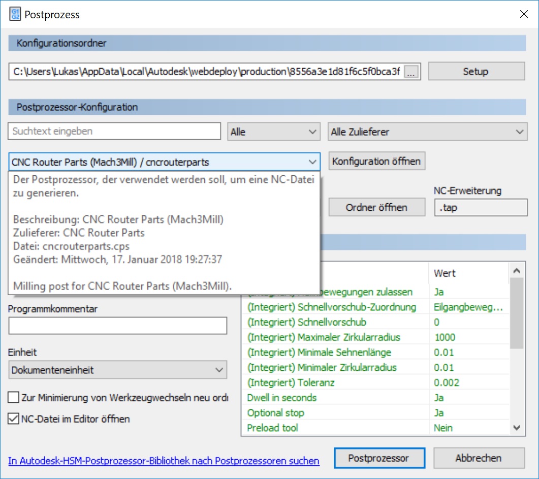
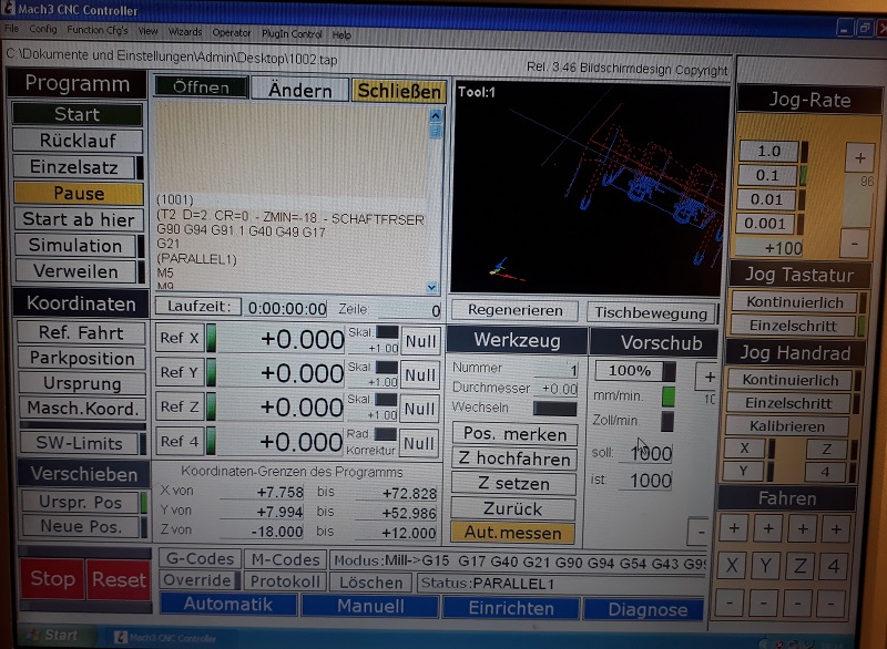
Now the final step is to export the toolpath as a readable file for the milling machine. I used the milling machine of Peter. It used the Mach3Mill software so I chose this option to get a .tap file. Now I can safe this file and transfer it to the working station if the milling machine.
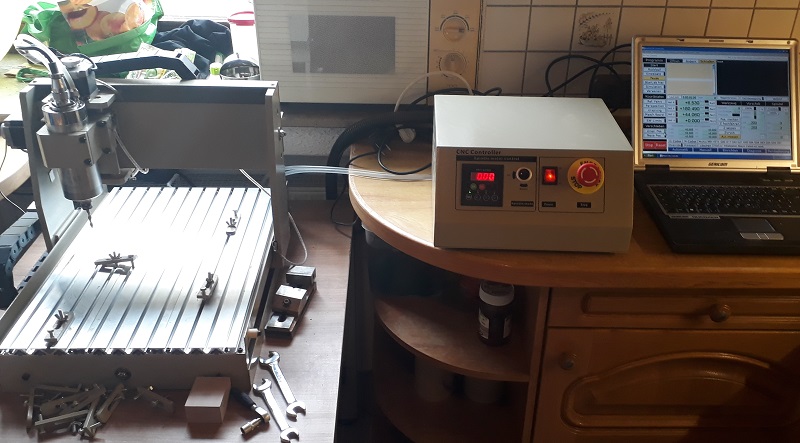
See below the used milling machine and the working station. The mill works with a water-cooling system. Thanks again to Peter who helps me to work with the machine. The milling machine in our FabLab doesn´t work in the last weeks because of to weak controllers for the motors. We have to fix it soon.
That is the surface of the milling software. The first step is to set the zero point. Therefor I moved the spindle manually to the correct point in X- and Y-direction above the workpiece. Not I zero the Y and X reference. After this I started the spindle and let is rotate as slow as possible. Now I drop the spindle in 0.01mm steps until it touch the surface of my workpiece. That is the zero point for my program.
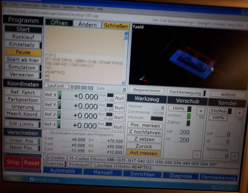
After opening the toolpath file you can see it in the black box at the right side. Also at the right site you can see the manually controlling panel for the movement of the spinde. There a steps up to 0.001mm possible.
Before milling the special wax I run a test process with a PU-foam plate. See the video below. It sounds good ant the movements are fluent precise.
See here the first trial with the milling wax. You find the safetydatasheet in the downloadsection below. Because the chips are fling around during the process I added a vacuum cleaner to remove the chips.
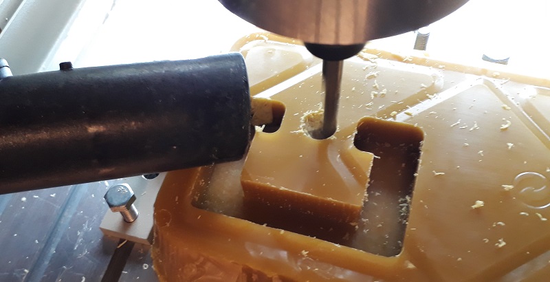 See here the workpiece after the first cleaning step. Now I had to change the tool to the smaller 3mm tool.
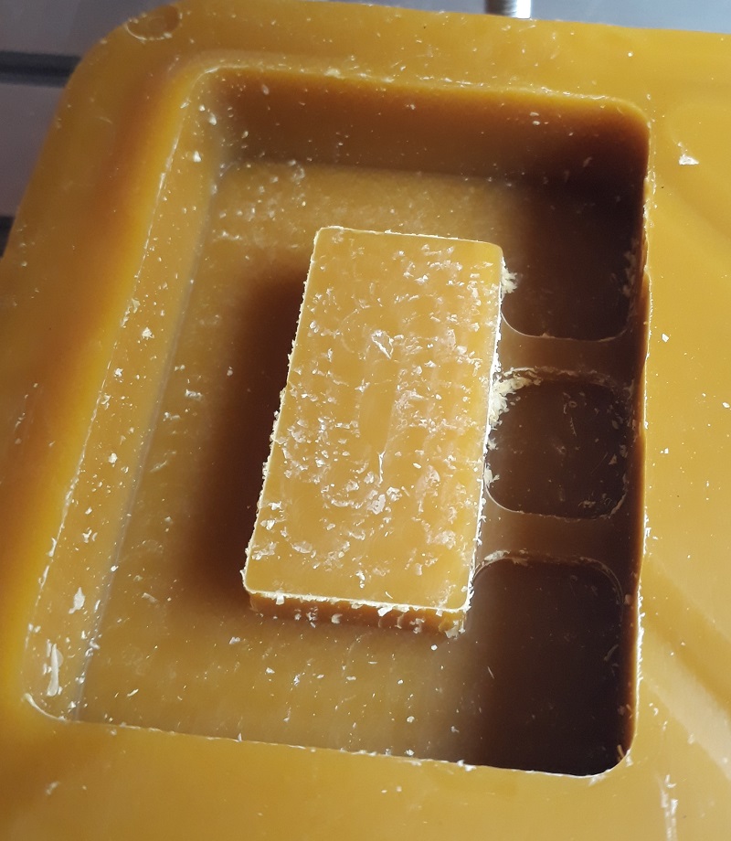
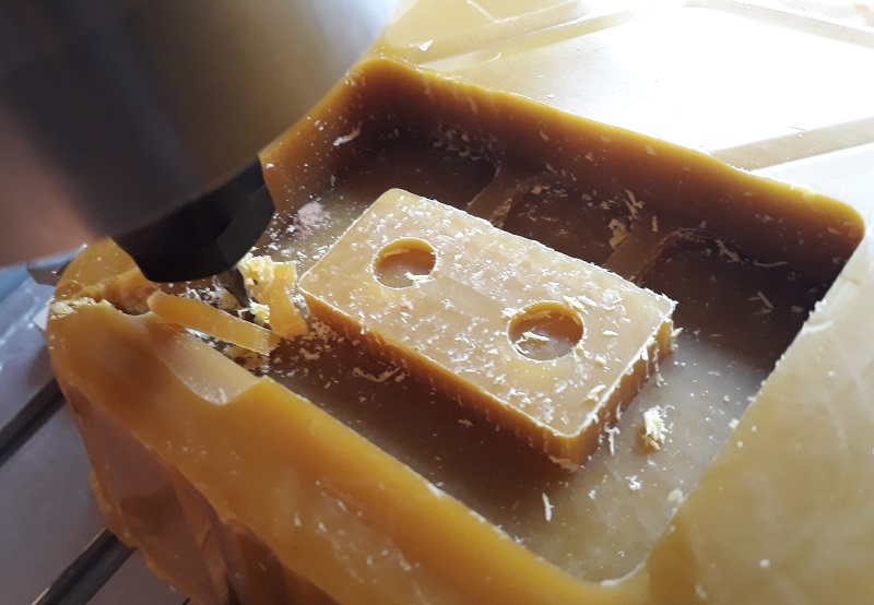
After changing the tool I had to zero the Z coordinate again. I used the same process than before for the fist leveling. But after starting the new job the process crashed. The reason is that the single chose the direct way from the starting position to the first job position. But in this setup the tool collided with the workpiece. Fortunately the wax is soft enough so there was no damage at the tool and also the broken part of the workpiece has no function so I could still use it. For the next tool changes I had to calculate this procedure for ne correct positioning.
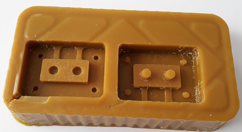
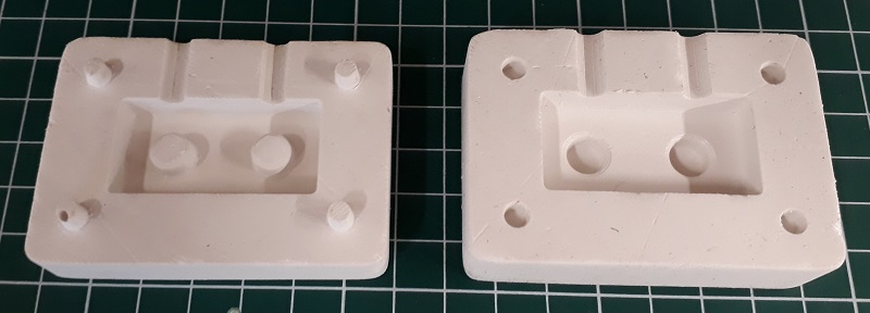
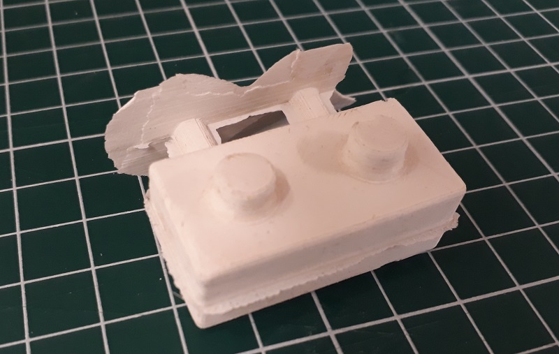
See here the both finished party after the second milling step and a little bit cleaning.
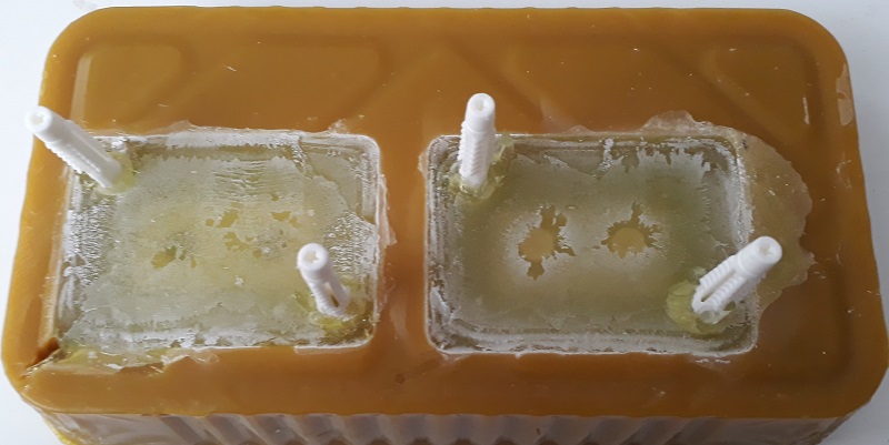
Couse I had not enough time to buy the correct form wax before my holydays during the break week, I tried to get the negative for with sanitary silicon. For a better remove I added the white sticks.

That’s what the silicone looks like after a week drying.
But after the first good looking impression I saw, that only the top 7mm of the silicone became hard. Also the transparent silicone become yellow and the wax faded. So notice: sanitary silicone is not the best chose for molding.
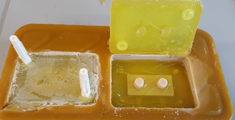
After removing the liquid silicone I noticed, that the wax became more soft under contact with the silicone. So the wax form was broken and I had to mill a new one.
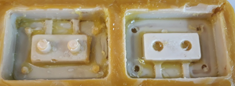
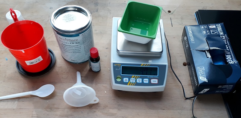
In the next try I used special sculpture silicone. I had to add 2% hardener and mix it . Therefore I used a precision scale and special containers. Find the important safetydatasheets in teh download section below.
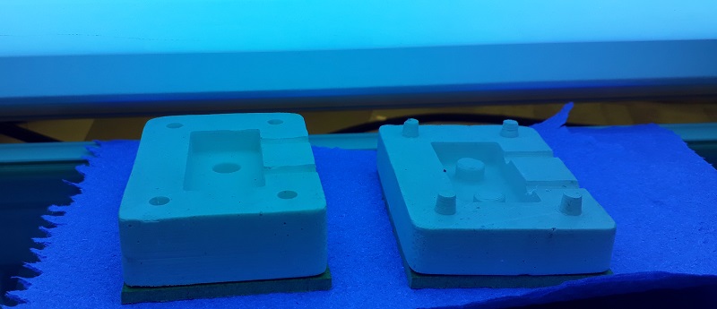
See here my finished negative forms. Think they look good enough for the next step. But they were very flexible so I had to cover the form with a back of wood.
I used a light activated glue so I used our UV-lamp to speed the process up.
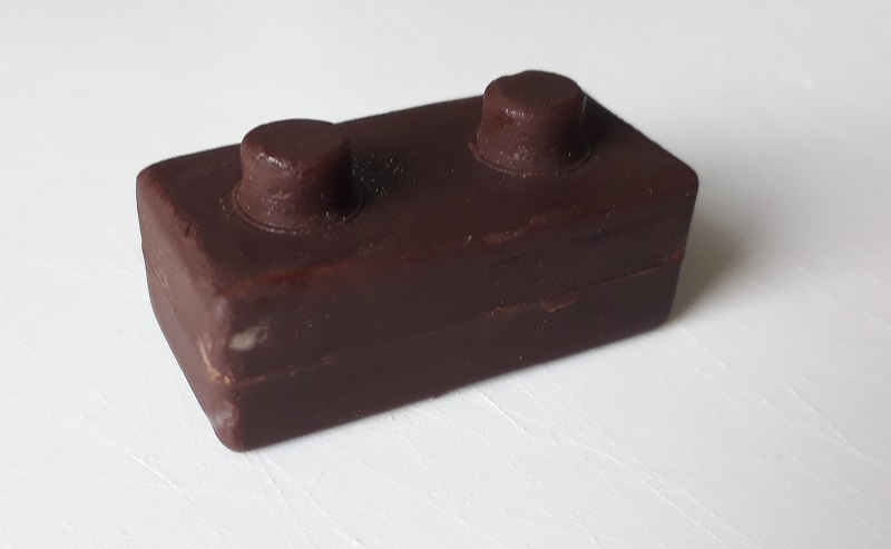
See here the final brick out of chocolate. After placing it for a few minutes In the freezer you can simply remove the brick. The next step is to build a chocolate brick wall.
Finally I casted a silicone brick.
Downloads
| Stl-files Molding and Casting | download |
| Safetydatasheets | download |
