Assignment 3:
Computer-Controlled Cutting
Task:
- make lasercutter test part(s), varying slot dimensions using parametric functions, testing your laser kerf and cutting settings (group project)
- cut something on the vinylcutter
- design, make, and document a parametric press-fit construction kit, accounting for the lasercutter kerf, which can be assembled in multiple ways
Work
In this assignment I like to start with a few test with our Lasercutter (Epilog Zing 24) with 50W. After I know the best settings I´d like to design my own press-fit system.Cutting setting
I decided to start with some test with the cutter-settings. We use our lasercuter with the Visicut software so I took a look at the setting possibilities. I found some propositions for different materials and thickneses. But for my prefered material of multiplex-wood with the thickness of 3,4mm there werent any given options so i had to test by my own. I designed the matrix below with Inkscape and tested it with diffend combinations of power and speed of the laser.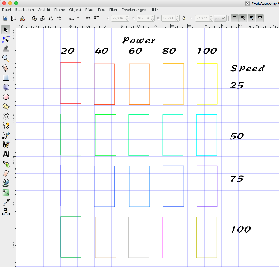 As you see I tested the range of power from 20 to 100 percent. Also I tested the speed from 25 to 100 percent. So i got 20 diffrent combinations of settings. To differ the single test rectangles i used diffrent colors. So I could choose different settings to each rectangle in Visicut.See here the result:
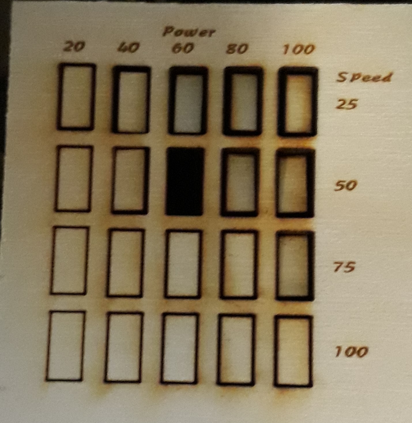
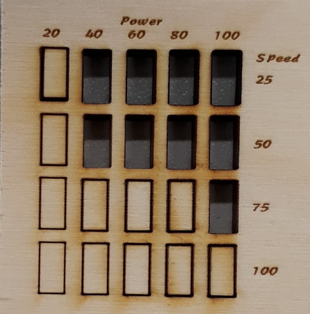
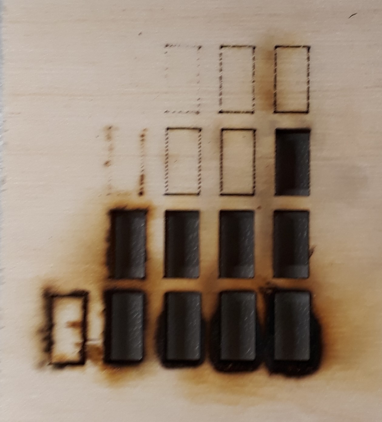
the first picture shows the finished testmatrix in the laserutter. The next picture shows that some settings are not able to cut the 3,4mm thick woodplate. the third picture shows the backside of the cutted matrix. As you see some of the rectangles looks like they werent cutted but burned out. So more power and less speed isn´t allways the best solution. Sometimes less is more. At this point I decided, that a setting of Power 60% ans Speed 50% looks like the best cutting result for my 3,4mm thick woodplate. The next step is to find out how thick the cutting-gap is. Therefore I designt the following testsheet with inkscape and cutted it out with the choosen setting.
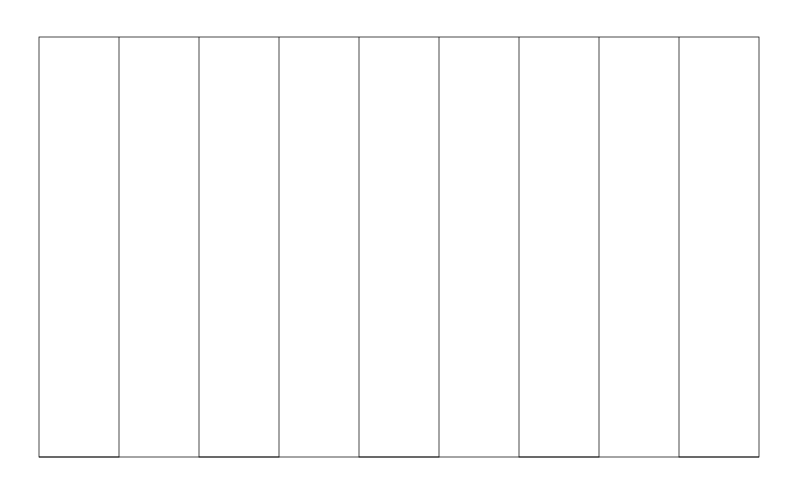
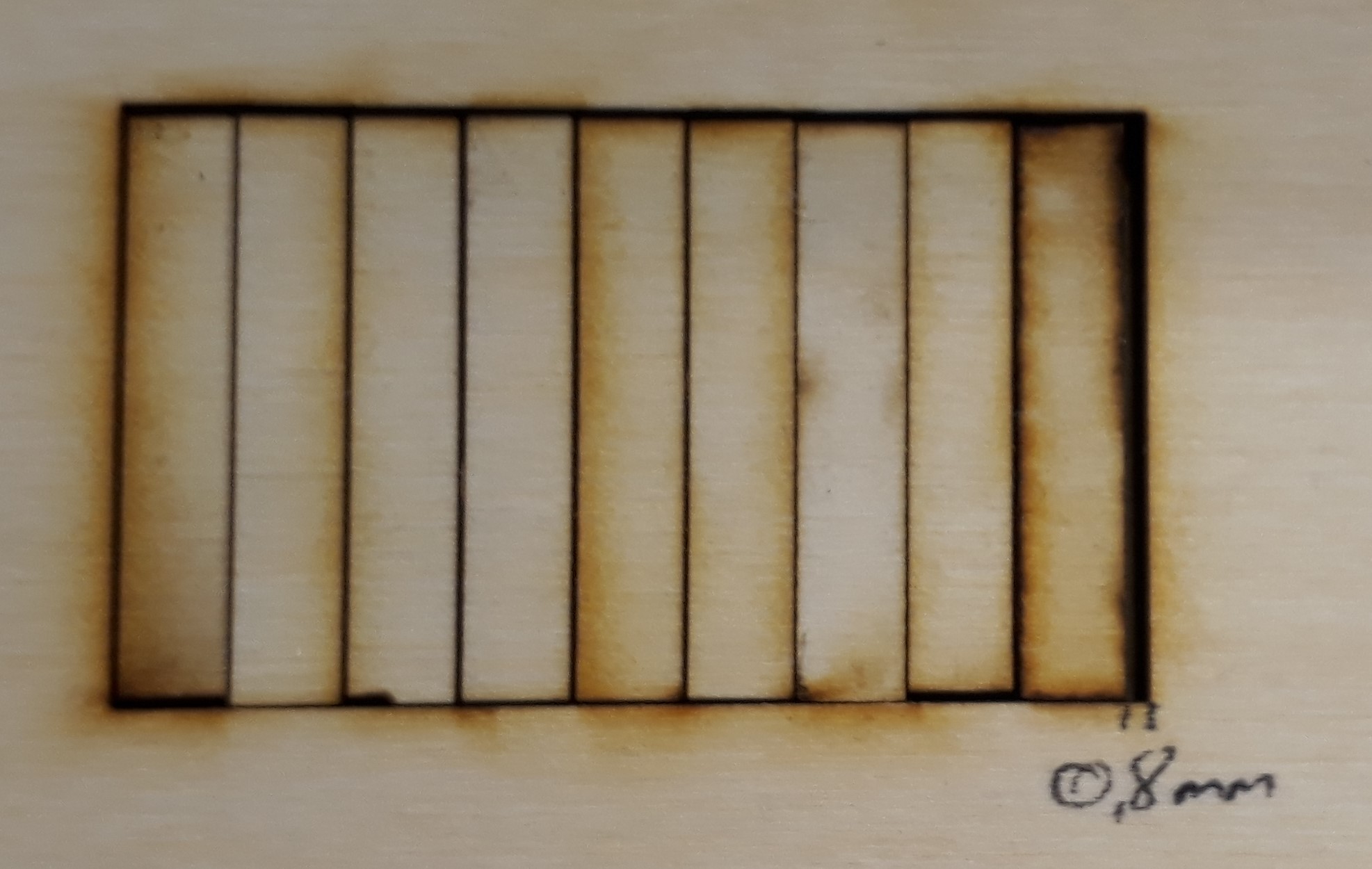
As you see the testsheet uses ten lines whitch makes the result more measurable. After the cutting I pushed all single rectangles to one site and measured the gap on the other side. The result is 0,8mm. So each cutting line results in a 0,08mm gap. With this knowledge i can start to design my press-fit system.
Press-fit system
At first I sketched some designs with the Adobe Sketch App I presented at Week 2. I´d like to design a system that offers a lot of possibilities to connect to each other without using a lot of different parts. So I choosed a system with two diffrent types of connection: A circle with nine gaps and a bar with six options to connect. Also the thickness should be the same like the width, so you can turn the single parts and it also fits. So here my first sketch: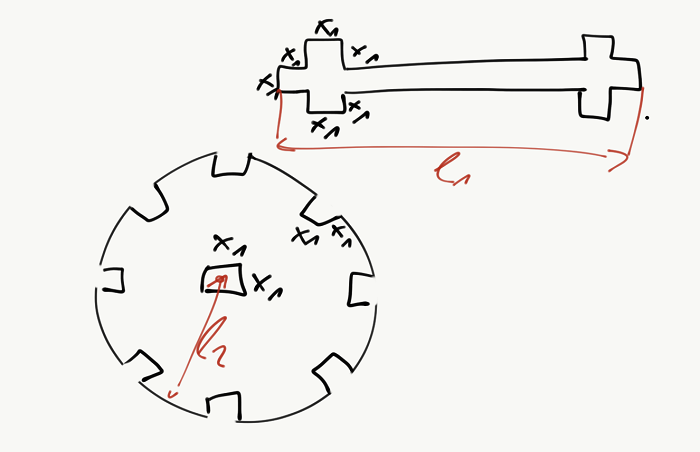
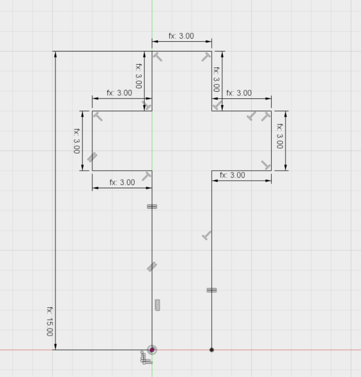
As you see I used a defined parameter "x1" for nearly each dimension. So there are a lot of possibilities to connect the single pieces with each other. The next step is to design a file for the lasercutter. Therefore I used Fusion 360, becaouse it is very simple to design a 2D-model for the lasercutter with this tool. First I opened a new 2D-Sketch and draw the rough contour of the bar of my press-fit system. As you see below I added some connections between the single lines. For example these "T" you see in nearly each corner means that the two lines should allways be orthogonal to each other. Aso if you edit the lengh of the lines they always will ne orthogonal. See the first contour below:
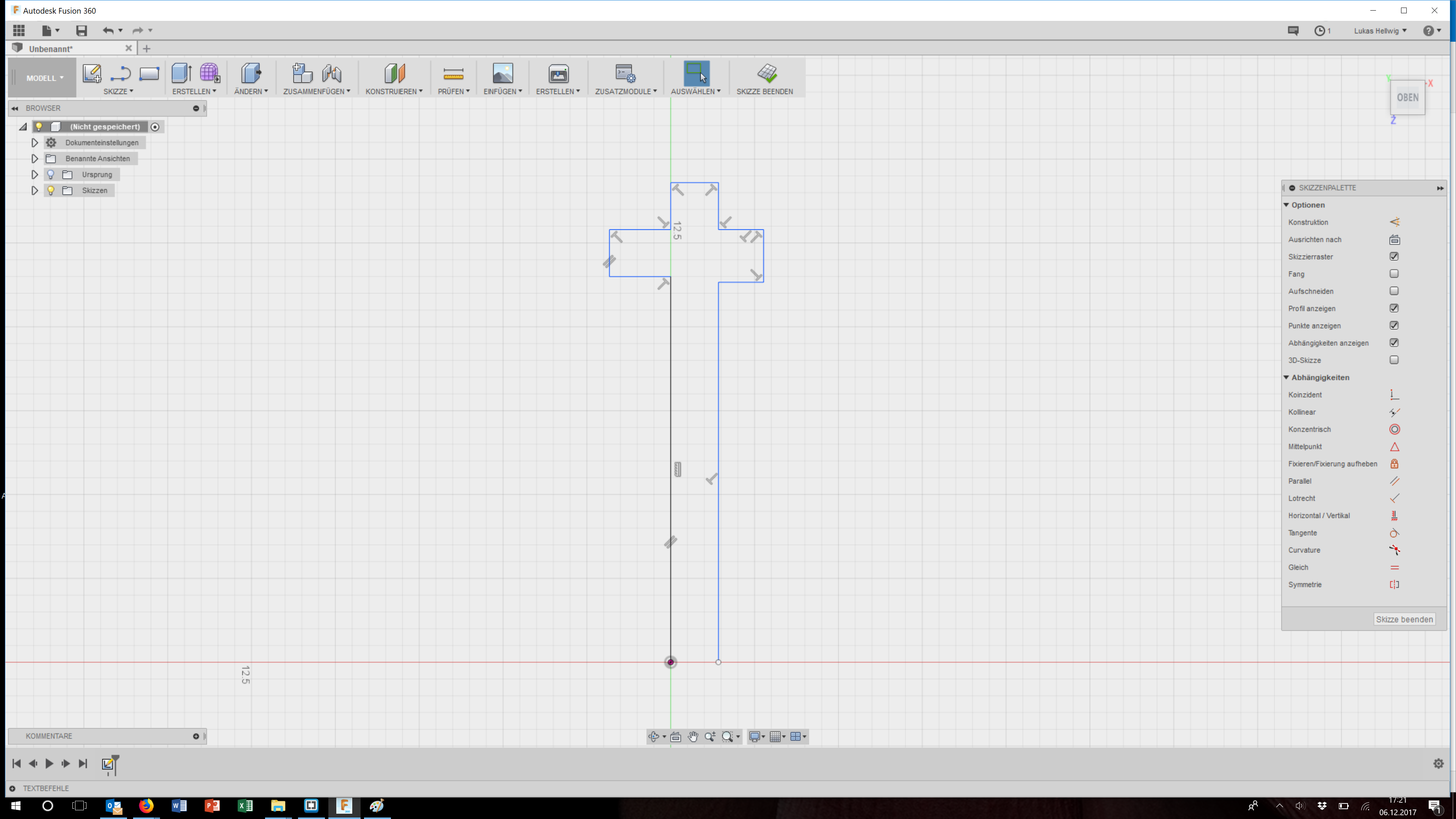
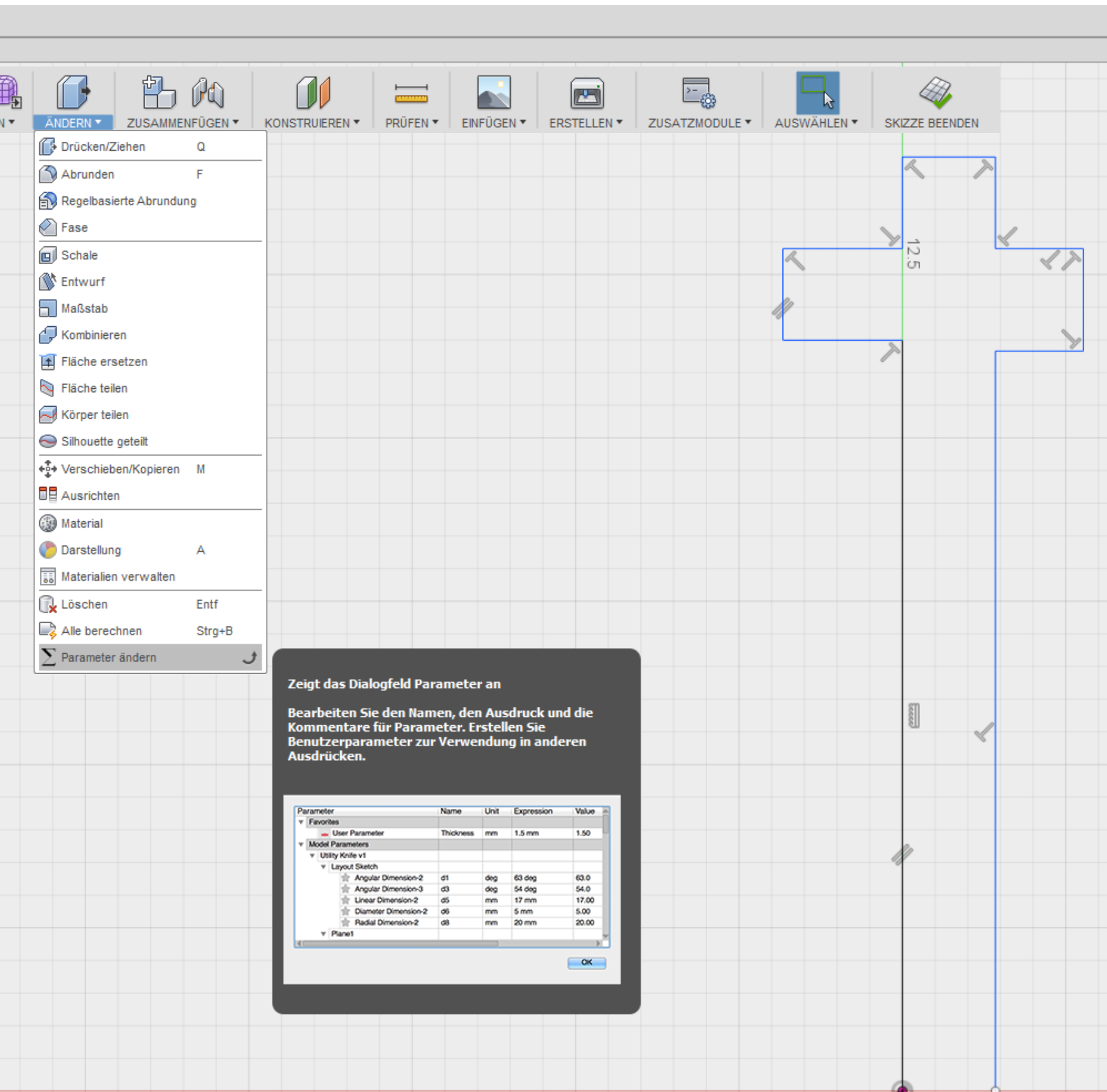
The next step is the dimensioning of the single lines. As I said before I´d like to use allways the same width of the conection points. So there is a good use of a fix parameter. Fusion 360 allows you to define paramter quite easy. Hope it is not a problem, that I used my Fusion360 in german, so the following pictures allwasy shows the german wording. But unter "Edit" you can find the option "change parameter":
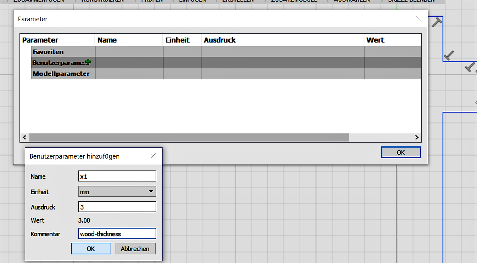
Here you can define diffrent parameters. As you see in the picture below I named my standart parameter "x1" like in the first sketch. In this picture i defined "x1" with a value of 3.00. In the commentar you can for example say what the parameter is for. In my example the 3.00 (mm) should be the thickness ot the wood i´d like to use for the cutting. As explained in the testing phase I´d like to use wood with the thickness of 3,4mm, so I can show later how easy to edit the single parameter to use my system with diffrent materials and thicknesses.
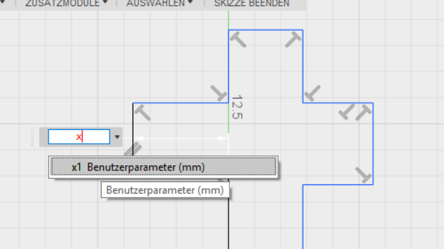
The nextstep is the dimensioning of my rough contour. Therefor you have to start the dimensioning modus and click at the line you want to define. If you defined a parameter before you can now use this parameter for example for the lenght of a line. Only type the name of the parameter in field for the lenght. Fusion automatically chance the coutour.
After defineing all single lines my coutour looks like below. You see the that I used only parametric dimensionings. Fusions allows you to use functions for dimensioning, so you can realize connections between single lenght. As you see on the left site there is is length defined as: 'fx: 15.00'. Here I used a function to define the lenght, in this example: 'x1*5'.
Now it is possible to chance the parameter 'x1' and Fusion360 edits the complete contour with new lenghts. As you see I also just draw one site of thr bar because i used in the next step the mirror function of Fusion to copy the same contour on the other site of the red line you see at the bottom. That finished my parametric designed bar of my press-fit system.
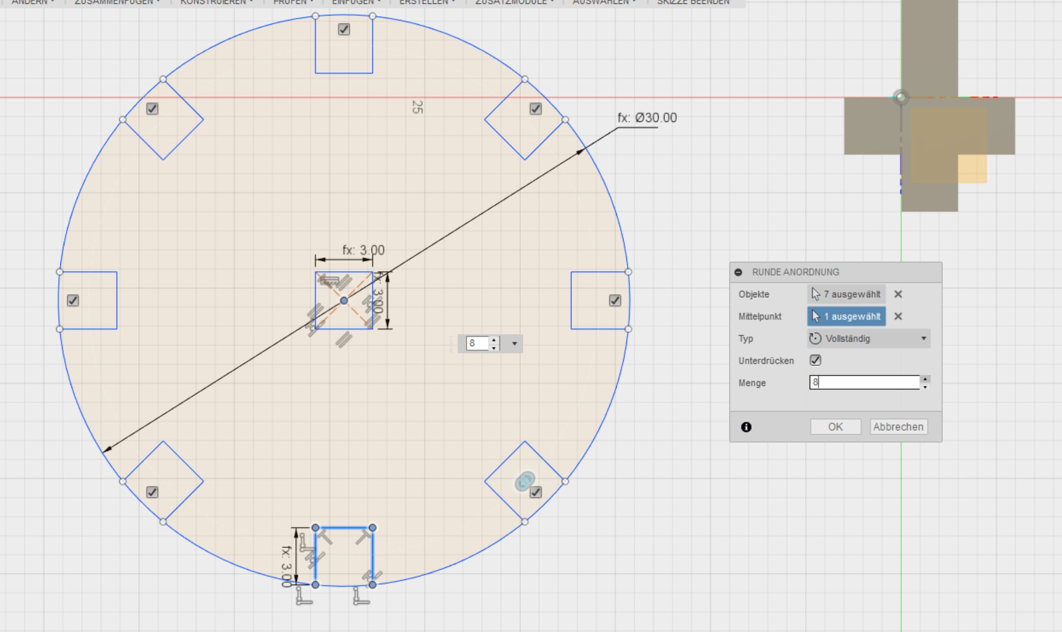
In the next step I designed the circle. I used the same parameter then before as you see in the picture below. Here I also used another function of Fusion to save some work. As you see the gaps in the cirle are alwasy the same. So I designed just one of them and circle it around the middlepoint of the circle. So i generated seven copys in the same distance.
As you see I didn´t use an chamfers. Normally they are very usefull to get a more easy connetion between single parts. I didn´t use them, because they reduce the contact surface between the parts and make the connection less stronger. I used quite elatic wood, so also a connection without chamfers works pretty good. SO i tried to keep the design simple and decided not to use them.
The next step is to export the contours to use them as a LaserCutting file. Here you have to click on the Sketch in the navigation-tree of Fusion 360 and choose the option "Save as DXF". This filetype is compatible with our Lasercutter so I only had to open it with the visicut software, choose the ideal cutting setting and send it to the cutter. during the first test cuts of my press-fit system I find out that our cutting-bed isn´t perfectly flat, so the focus isnt able to adjust ideal. SO I hat to 'try and error' to find a setting with with it is possible to cut more than one peace. So I Find out the following setting:
- Fokus: 500
- Power 70
- Speed 40
.jpg)
.jpg)
.jpg)
Vinyl-cut
It was my very first time I used our vinyl-cutter so I had to learn the process from te begin. We use different types of vinyl-cutter in our lab. The Silhouelle CAMEO3 and the Silhouette portrait2 for our daily business and our open evening. And in addition we have got the Roland CAMM-1 GR-540 for bigger project with a maximum width of 1600mm. The Roland-cutter wasn´t in use before so I had to install it. I documented the instalation below.I started with the small CAMEO3 cutter because it is quite simple to handle. My first cut I´d like to do was a sticker for my phone. I choosed the logo of my favorite nfl-team: The Atlanta Falcons (sorry the Patriots are only number two ;-)). I searched in the web for a logo with high contrasts, because for the next step a high contrast ist usefull. The silouette-cutter have their own software which is quite powerfull. You can design your own logos in it our create cutting-files out auf fotos. So the software can detect color-differences and generate there a cutting line.
There are some adjustment bars with which you can set the correct setting to chose the right lines to cut.
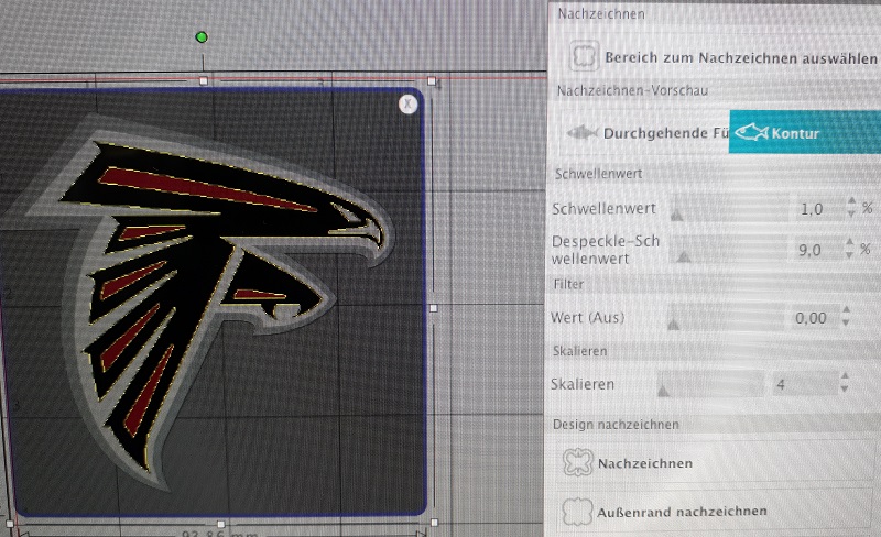
So it is very simple to generate cutting files out of high-contrast pictures. You also have a lot of options to change the settings.
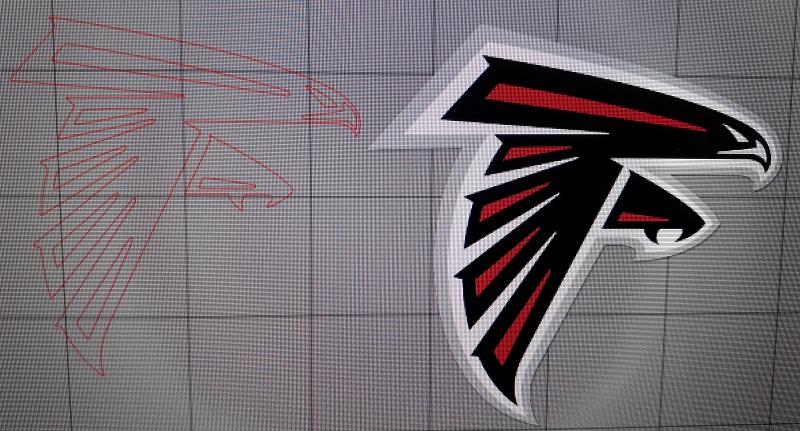
See here the generated cutting path.
when the cutting file is generated it is time to prepare the cutter. You have to put the foil you´d like to cut (in my first setting it is a sticker-foil) on a special surface and then load the cutter. The CAMEO3 is able to autoadjust, so you only need to select the correct foil in the software and the cutter uses the right settings himself. So the next step is to send the file to the cutter and watch him doing his job.
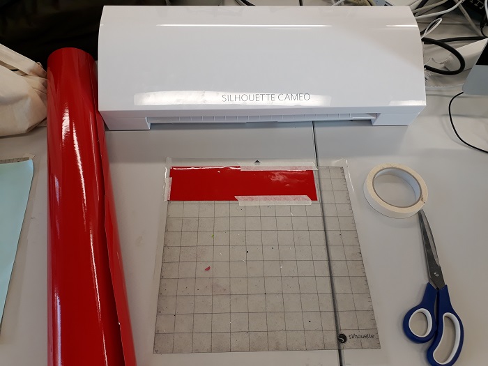
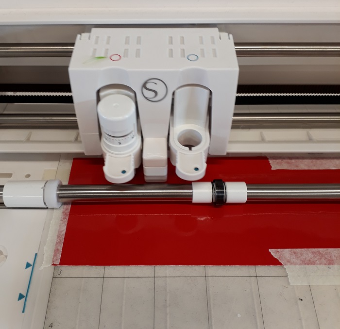
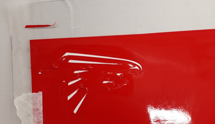
As you see in the picture below, the resolution and the necessary curves was very small so the cutter moves some of the cutted parts from the underfoil. Luckily all of these party i had to remove anyway.
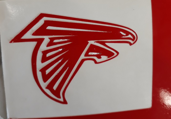
Becaouse my sticker was separated in diffrent party I had to use a transfer foil. For this small part i used masking tape. See the result below:
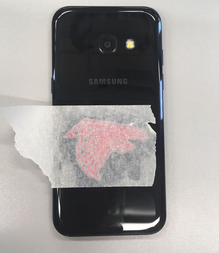
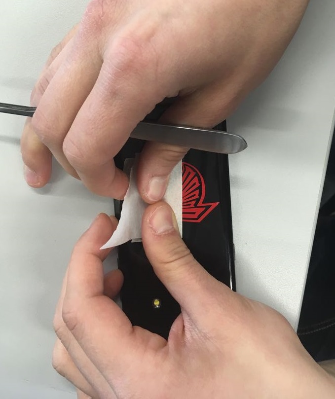
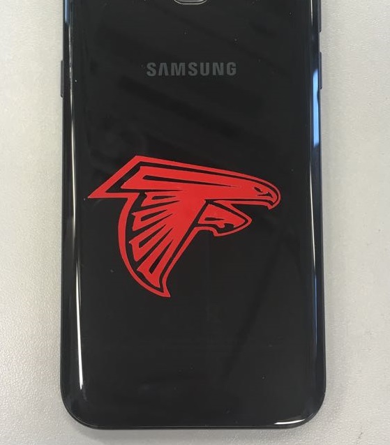
In the next step I´d like to create a Fab-Academy-Shirt for our team. The proces was quite the same, but you have to mirror all your picures and use a thermal foil. Also chance the settings to termal foil in the software for the right cutting settings. After the cutting i had to remove the unnecessary parts, stick the foil on the right place on the shirt and put it for 35seconds in our 180 degrees celius thermopress. The last step is to remove the carrier foil.
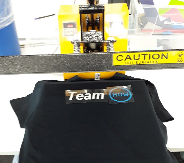
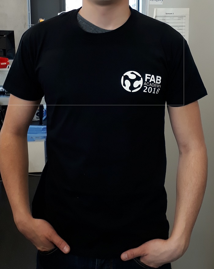
If you would like to add a sticker on the backside of your shirt it is important to use a special foil in the thermalpress to save the sticker at the frontside. Yout can find the design of our FabShirts in the downsload area below
In the next step I wanted to use our big Roland cutter for the very first time. It is a quite more powerfull cutter which can also cut cupperfoils for example. It was quite hard to install all necessary drivers and software tools. You need to create a account and register your cutter. The documentation isn´t very precise so it was more 'try and error' to get this cutter work.
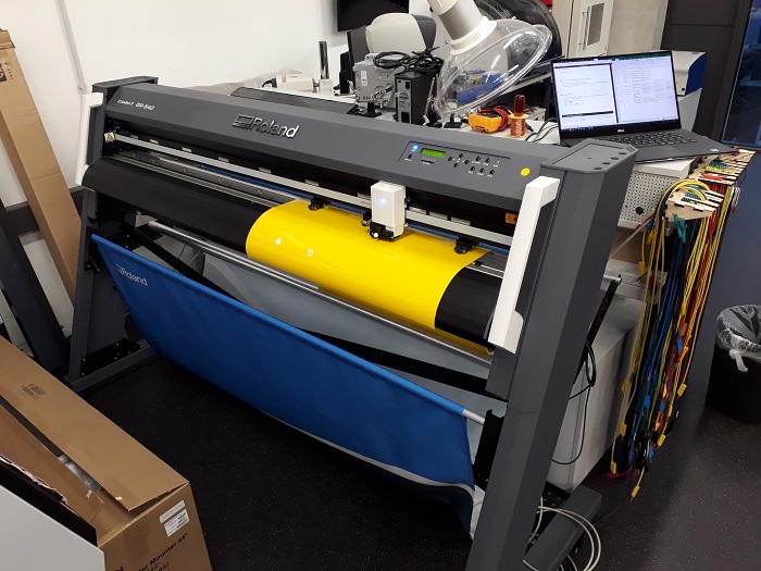
The software the Roland-cutter work with isn´t that powerfull than the silouette software but you can connect it with profesional software like illustator. The basic tools are also included in the Roland software so I started a first try with a world map. The process was quite similar with the silouette software, but you can´t edit the cutter-settings in the software and there is no help which setting is the best for which material.
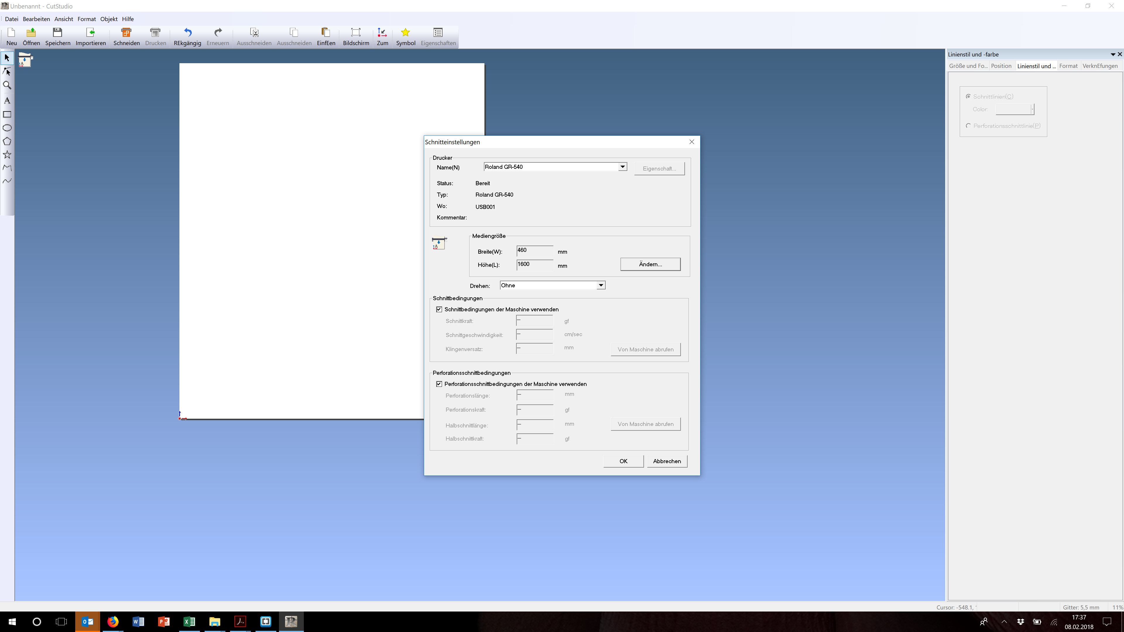
See the settings to generate ja cutting path out of a black and white picture below:
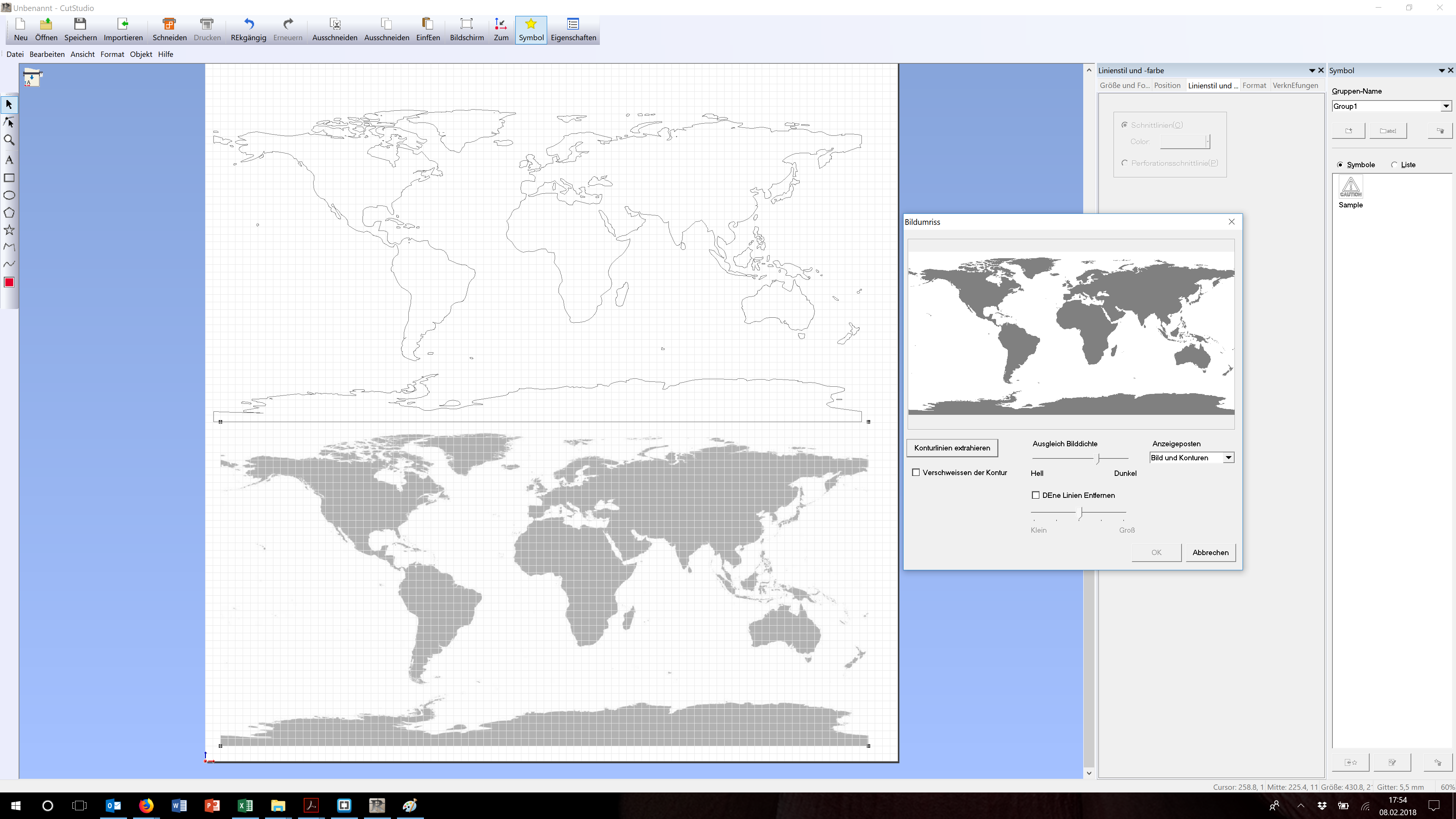
So before i started the big cut I used the option to do a testcut directly on the cutter. With the first standart setting the power of the knife was not enough to cut the foil completely so I set the force with the slide control from 0 to 1 and started a new test cut. This looks better so i started the big cut.
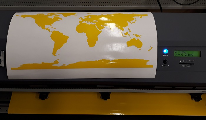
The final product looks great an the cutter works well. In the future i have to learn more about the settings and how to connect the cutter with professional software. During the next weeks there will be a lot of ideas for great cuts.
Downloads
| Cutting Tests(zip) | download |
| Pressfit sketch and model(zip) | download |
| FabAcademy shirt design (zip) | download |


