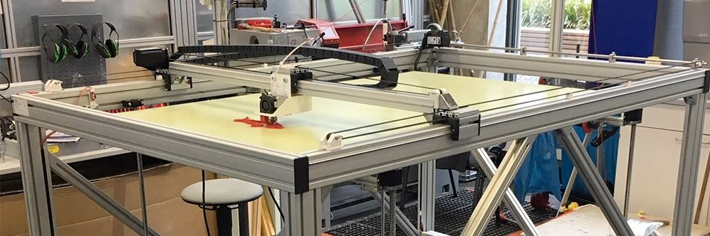
Big 3D-Printer
With a maximum volume of 150 x 90 x80 cm
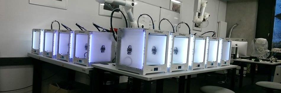
Some of our Ultimaker
We´ve got more than 25 3D-Printer of diffrent types
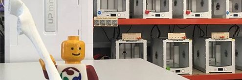
Greeting
Our best employee in HRW FabLab
Assignment 6:
electronics design
Task:
- use the test equipment in your lab to observe the operation of a microcontroller circuit board(group project)
- redraw the echo hello-world board, add (at least) a button and LED (with current-limiting resistor) check the design rules, make it, and test it
Work
I started my assignment with the addition of the fab-library to my eagle. Here I will find all necessary footprints so I thought. Before we ordered all electronic party we wanted to use. Later I noticed that the footprints aren´t fit to the fablab-library. So I had to search for the correct ones.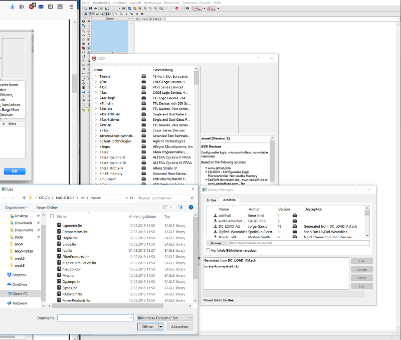
At first I added all necessary elements to my circuit diagram. Also a switch and two leds. One I wanted to use to show the power supply. The other for a onboard programmable led.
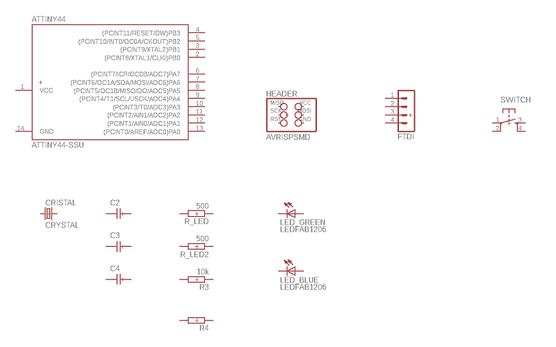
As you see I like the label function a lot. In my opinion the circuit diagram becomes more clear and I don´t miss any connection.
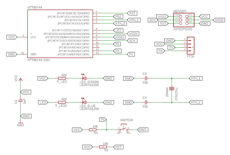
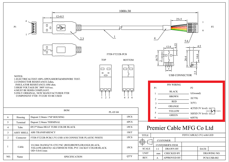
As you see I started with a FTDI-connection with four pins, but then I noticed, that my ordered cable uses six pins. So I had to take a look in the datasheet to update the diagram. See the necessary information of the cable in the red box below.
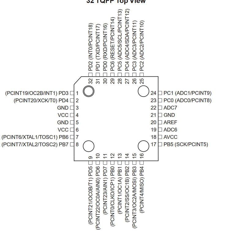
With the change of the ftdi connection I decided to upgrade the controller to a Atmega328P to get more power and more options to develop the board. Also I hat a lot of trouble with the setting of the fuses with my programmer, so I decided to use the Arduino software to burn the bootloader.
For this step I had to upgrade my layout and to find out witch are the necessary pins. Therefore I took a look at the datasheet of the Atmege328P. See the relevant figute below.
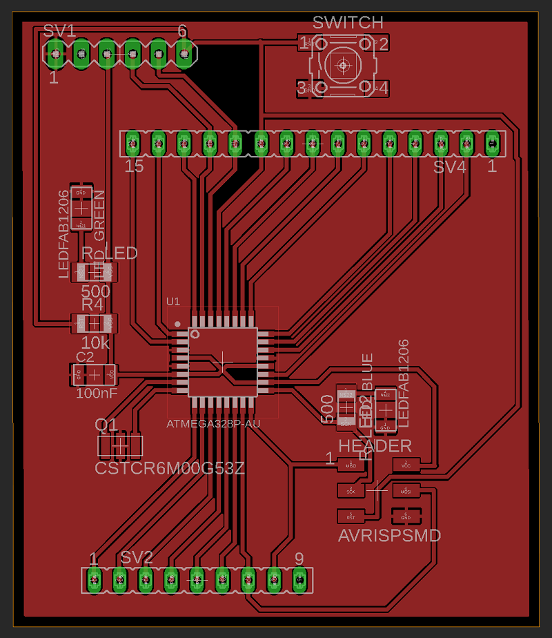
See below my upgraded circuit diagram with the new controller, FTDi and also a resonator. I decided fore a resonator to save space. Also I added pin headers for all othe pins to make the board a great base for next development steps.
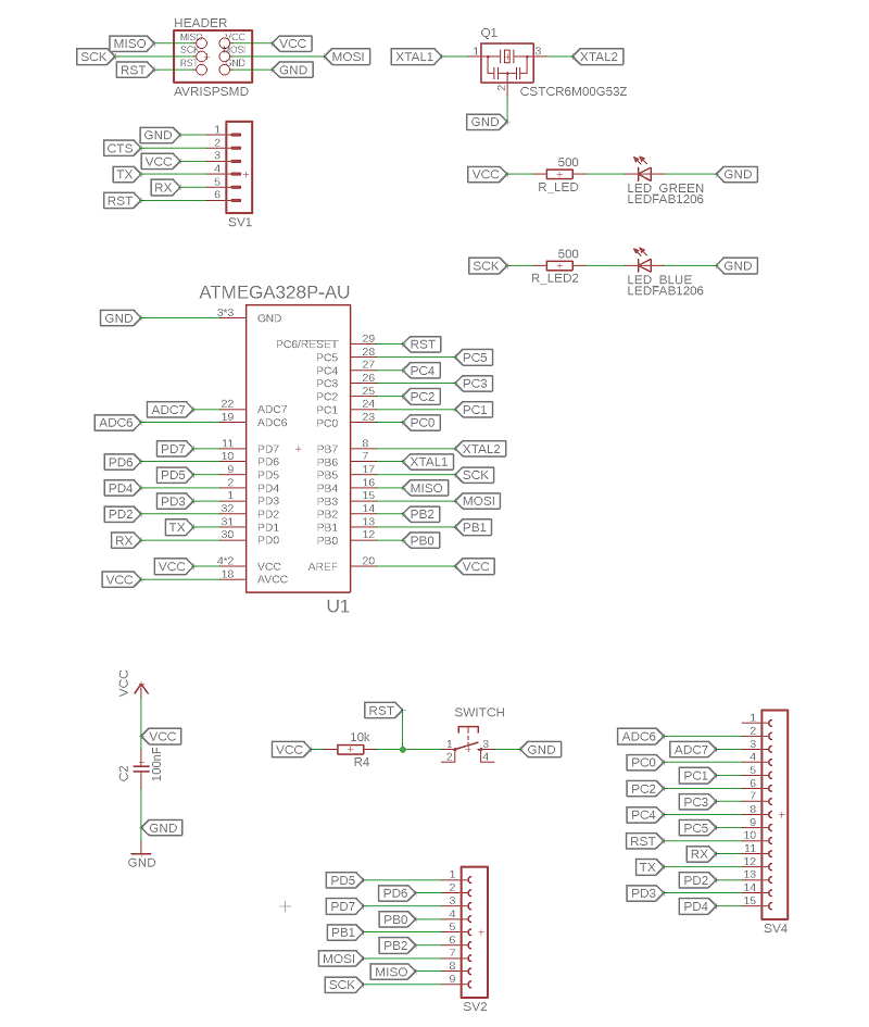
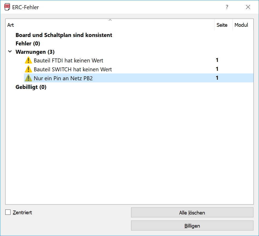
The ERC gave me three warings, but they were not critical. Only the PB2 net wasn´t connected so I changed it.
In the next step I designed my board layout. I tried that before with my programmer so there was not a lot of problems. To check my Layout I used the eagle DRC. I used the standard adjustment, because there are no special requirements and the standart settings are a good chose for a milled board. So see the settings below:
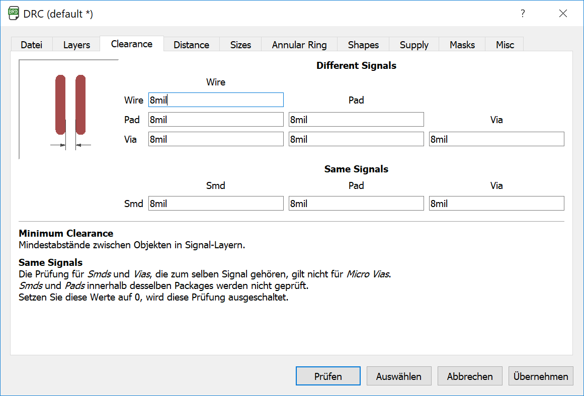
Here I set the clearance for the single contours.
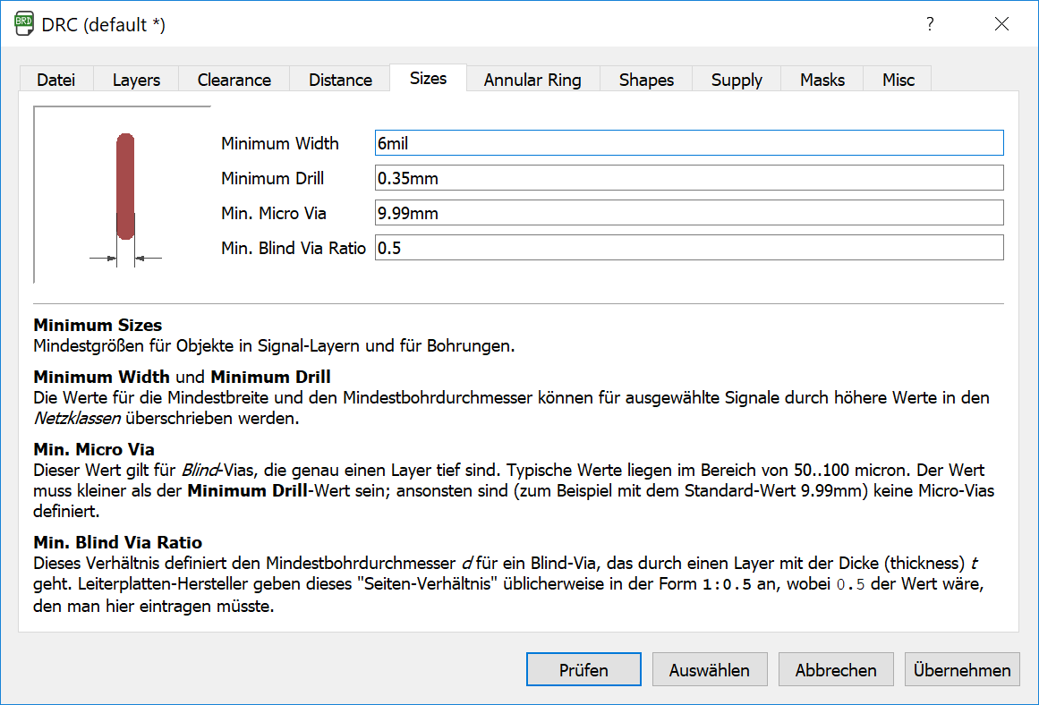
Here I set the with of the single cuts. Blind-Vias were not expected so i didnt touch this values. After setting the wise values I startet the DRC:
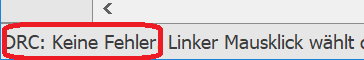
In the first step I had one air-wire, because I didn´t connected the wire exacetly to the footprint. After this small correction there was no more mistakes.
You find more informations about the setting of the DRC in
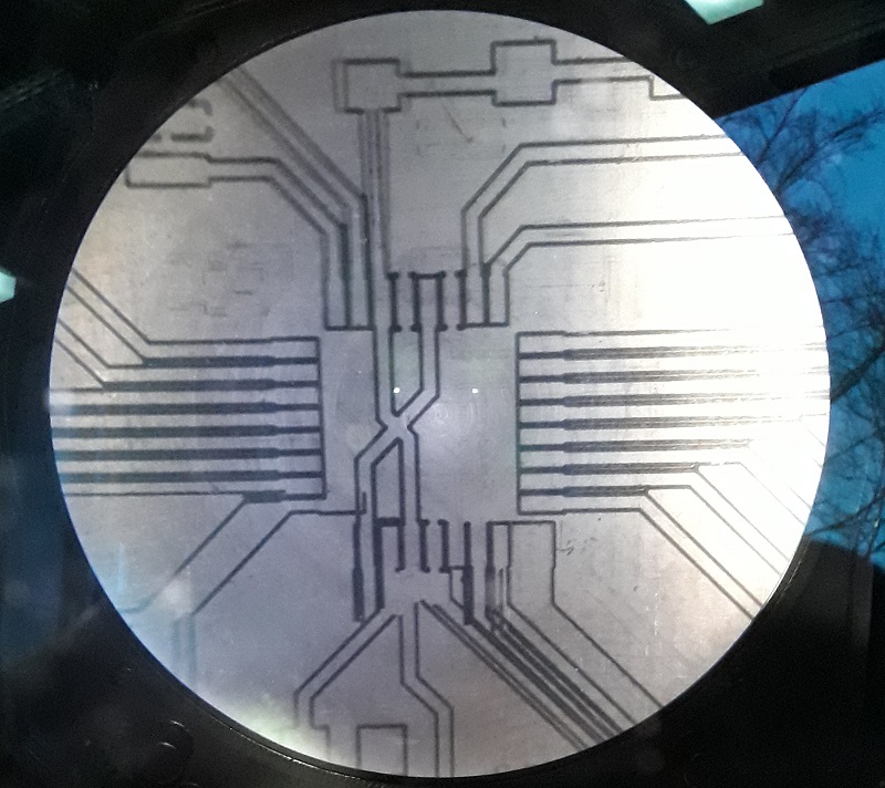
Now It is time to mill my board. Therefore I used again our LPKF milling machine. It was the same process than in the programmer-assignent.
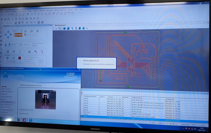
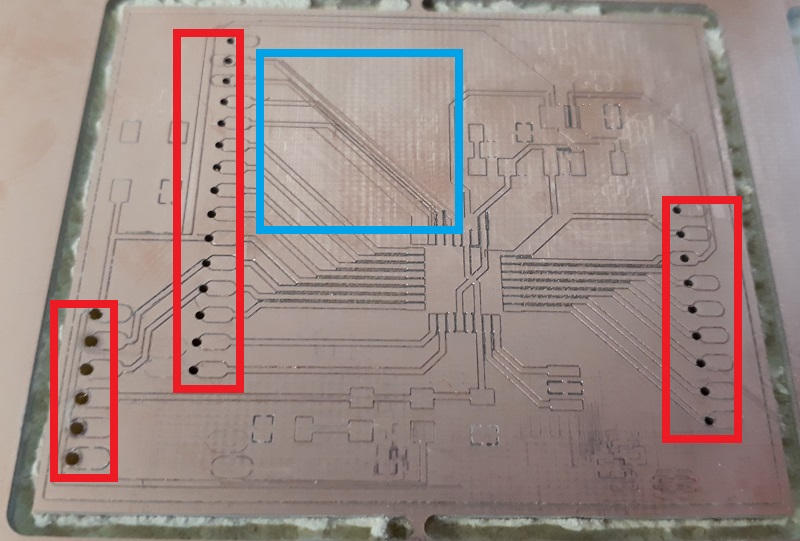
After the machine finished the job a noticed some big mistakes. As you see in the red frames the holes weren´t in the centre of the footprints and also the lines In the blue frame crosses each other. During the milling process the board moved a little bit so the board fails.
See below the first try and the finished board after fixing it at the surface. I looks definitely better than before and there weren´t any problem with movement again.
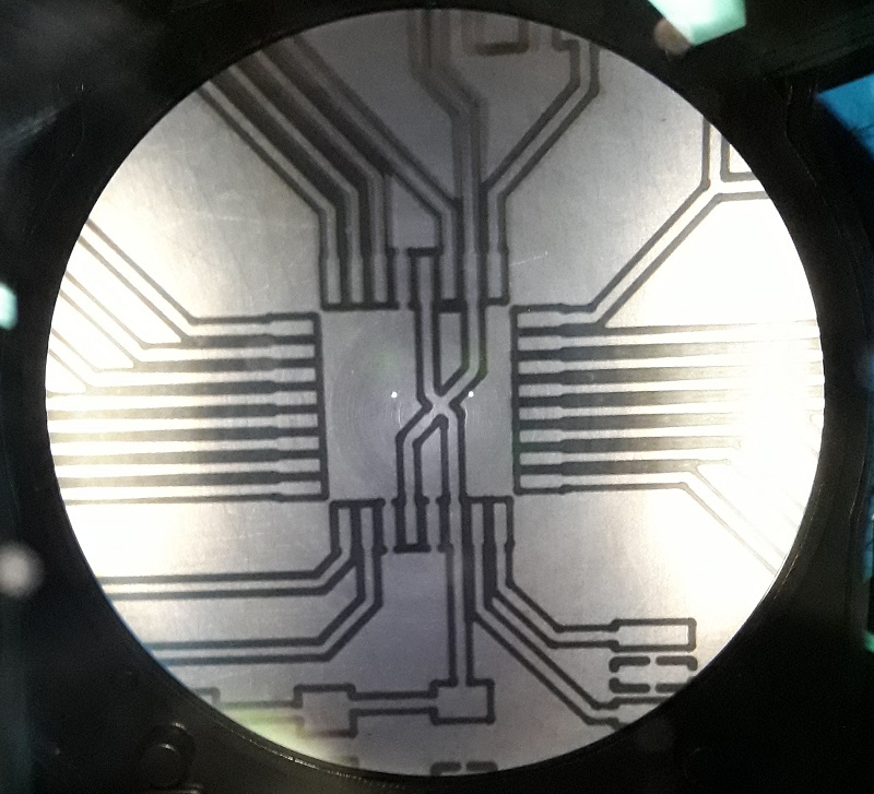
See here the complete and finished board:
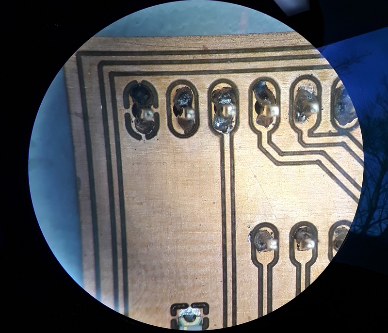
After putting all electric parts on the board I had to solder the single pins by hand. I used our microscope to fix the pins without connect them with each other.
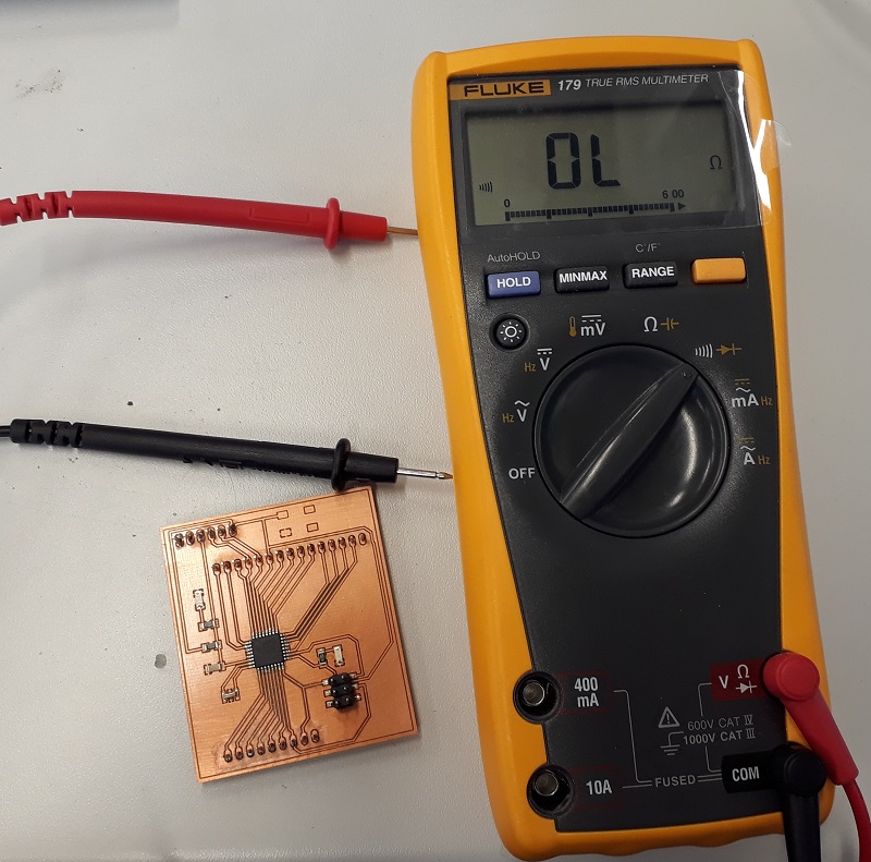
In the next step I tested if all parts were connected correctly. Therefore I used our multimeter. Here I found a problem with my GND. I don’t get connection in all my parts of the board. The reason was the changed setting of the milling process. I doubled the lines around the footprints so the last connection gets lost.
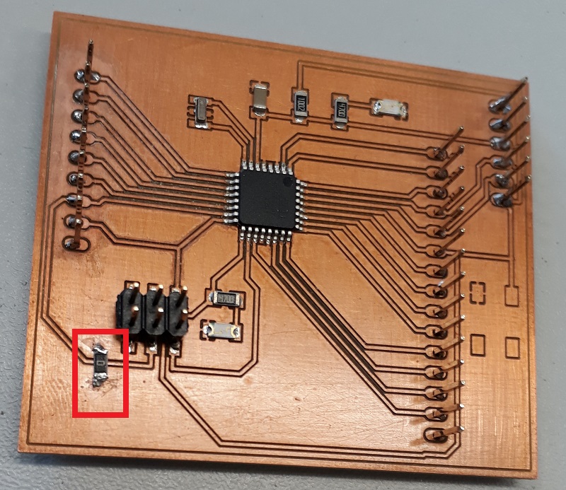
To solve this problem I used a 0ohm resistor to connect the both GND fields. See the red frame below. Doesn´t look really pretty but for a first test is will work.
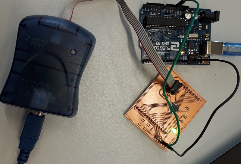
Now I tried to burn the bootloader at the board. I used first my ISP-programmer and a Arduino for the external voltage. As you see the voltage led works, but the bootloader cant burned at the board. Lets start searching for mistakes….
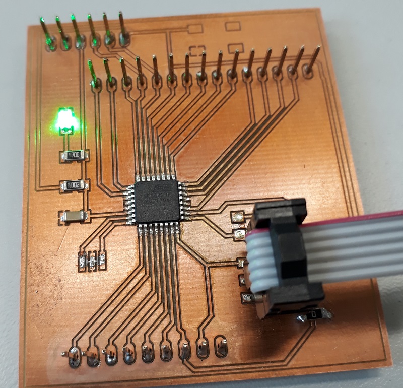
First I changed my programmer to a Diamex-AVR, that doesn´t work better. After that I cut the led but that also doesn´t change anything. The last step I removed the resonator and changed is to a non-smd type. The footprint of the smd resonator wasn´t correct so there was a problem with the connection. With the new cristal and the two resistors it works:
Now I could burn the bootloader and also send programs via Arduino. But every time I tried to contact the board it chrashed. Until now i have no idea why this happens. In the next step I will try to build a new upgraded board with the repair of the problems.
Update
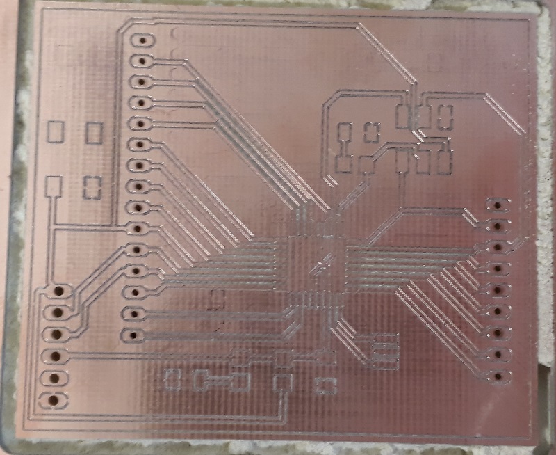
After my first self-developed board had some problems I upgrated the design and fixes the main Problems. As you see in the picture below the new board get a little bit bigger cause i used a cristal instead of a smd resonator. Also I changed single lines to avoid the GND bridges.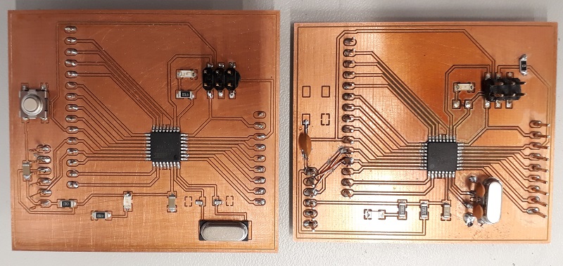
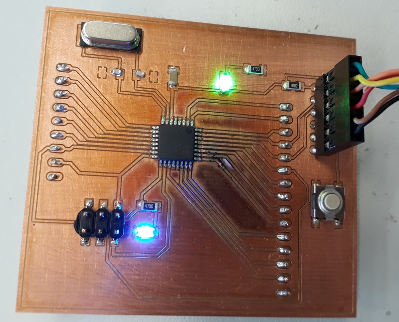
After this small update there are no problems with the bootloader anymore and also it is possible to program the board. So for example the led blinking program with the onboard led works well.
After some programming processes there are again problems and the programmer can´t find the connection again. It only works every third time. After a lot of research I found out that the AtMega has got problems. So after a rebuild of this design everything works well. So it was a hardware problem not one of my design.
Downloads
| Fab-library | download |
| Datasheet FTDI | download |
| Datasheet Attiny44 | download |
| Datasheet Atmega328P | download |
| Hello-Board Eagle Data | download |
| Hello-Board Eagle Data-Update | download |
