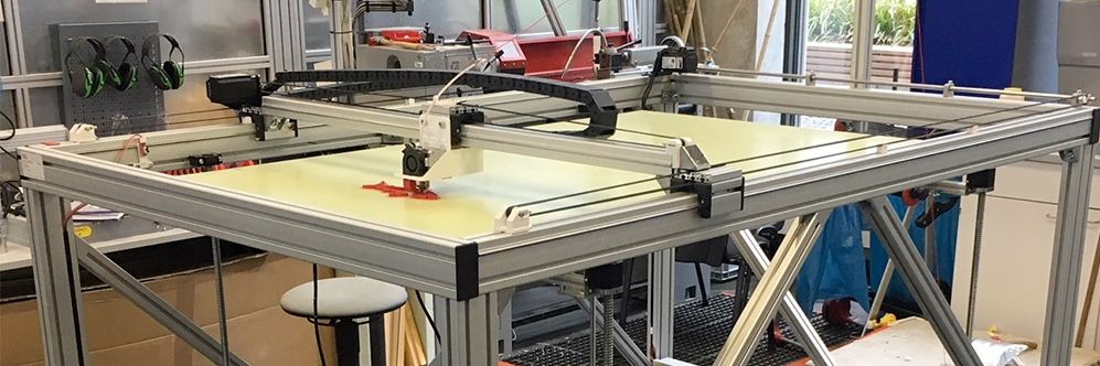
Big 3D-Printer
With a maximum volume of 150 x 90 x80 cm
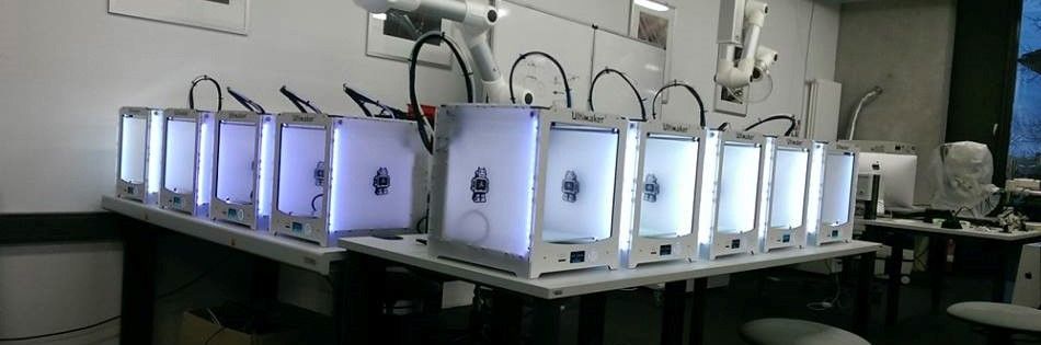
Some of our Ultimaker
We´ve got more than 25 3D-Printer of diffrent types
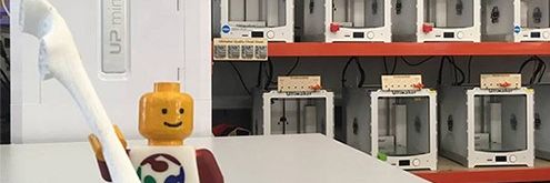
Greeting
Our best employee in HRW FabLab
Assignment 10:
Input devices
Task:
- measure the analog levels and digital signals in an input device (group project)
- measure something: add a sensor to a microcontroller board that you have designed and read it
Work
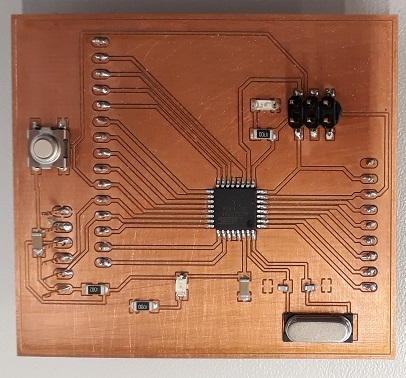
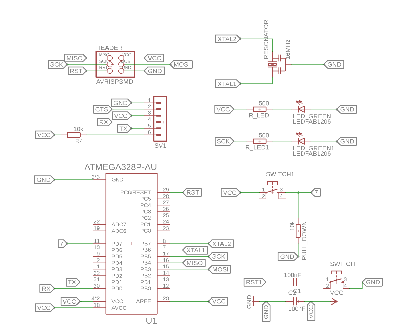
For this Assignment I wanted to use my own developed board from week 6. I developed it as a Arduino remake to use the Arduino IDE for the programming process. There are a lot of sensors for Arduino I wanted to try out but they use special pin configurations. I used the same controller than a Arduino Pro (AtMega 328 with 5V and 16MHz) so I could transfer the pin names of a Arduino Pro to my layout. In the Arduino IDE they are named with raising numbers from 0 to 17.See below again the layout of my used board:
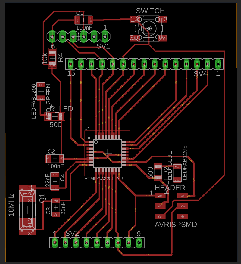
As you see in the finished board below additional to the FTDI and ISP-headers I have got two rows of pins. Until now I didn´t know exactly which pin is connected to which controller pin.
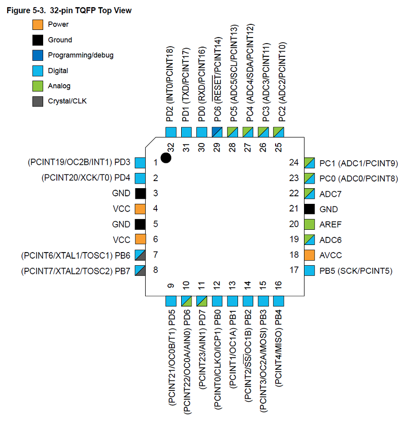
In my board scheme I named the lines like the controller outputs (For Example “PC2”) but sometimes they have different names like PD0. That is also the RX connection. In the first step the function as a RX-pin was necessary but for the next step I need to know the controller name. So I had to check again the names with the datasheet. See the names below:
Now I had to check how each controller Pin is named in the Arduino IDE. Therefor I used these pinout diagram below. Here you find the missing information So for example the controller pin PB1 is the pin number 9 in the Arduino IDE.
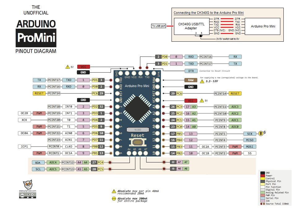
Now I know which pin at my personal board equates to which number in the Arduino IDE. See the translation in blue below:
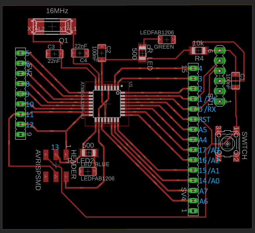
As you see I missed to connect the pin 13 external the ISP header. Also there is no additinal pin for the VCC. In the first step i Can use the ISP header to connect the 5V but thats not the best solution. I have to upgrade my board for the next weeks.
Taster
I started with tha most simple input device I found: the button. In the first step I wanted to learn how to connect a input device to my board and how to use it. Because I´m able to use the Arduino IDE I could also use the Arduino sensors and the quite good documentation of it. So for example you can find HERE the explanation and some example code for the button.The button has only two pins. It works like a switch which is normally open and only closed during the pushing. You can use it to open/close a electric circle but also with a microcontroller to track it as a input.
In my first step I wanted to show both types of use. Therefor I used the following example code as a basis.
int LEDblau=6;
int taster=7;
int tasterstatus=0;

void setup()
{
pinMode(LEDblau, OUTPUT);
pinMode(taster, INPUT);
}

void loop()
{
tasterstatus=digitalRead(taster);
if (tasterstatus == HIGH)
{
digitalWrite(LEDblau, HIGH);
delay (5000);
digitalWrite(LEDblau, LOW);
}
else
{
digitalWrite(LEDblau, LOW);
}
} See in the next step my program with the insert explanation.
int LEDgreen=6;                 //a variable with the name "LEDgreen" and the value "6" is initialized
int taster=7;                   //a variable with the name "taster" and the value "7" is initialized
int tasterstatus=0;             //a variable with the name "tasterstatus" and the value "0" is initialized, this will be my the varable whitch saves the status of the button
int LEDred=5;                   //a variable with the name "LEDred" and the value "5" is initialized

void setup()                    //Here starts the setup of the program
{
pinMode(LEDgreen, OUTPUT);      //the pin with the name LEDgreen (number 6) is set to an output
pinMode(taster, INPUT);         //the pin with the name taster (number 7) is set to an input
pinMode(LEDred, OUTPUT);        //the pin with the name LEDred (number 5) is set to an output
}

void loop() // here the program starts
{
tasterstatus=digitalRead(taster); //here the pin number 7 is readout. The call is saved under the variable “tasterstatus”. Because it is a digital readout the variable can get the status “high” and “low”
if (tasterstatus == HIGH)         //if-question. If the status of the variable “tasterstaus” is “high” the following brackets starts
{
digitalWrite(LEDgreen, HIGH);     //the green LED is turned on
digitalWrite(LEDred, LOW);        //the red LED is turned off
delay(500);                       //wait for a half second
}
else                              //the programm of th efollwong bracket starts if the "tasterstatus" isn´t "high"
{
digitalWrite(LEDgreen, LOW);      //turn green LED off
digitalWrite(LEDred, HIGH);       //turn red LED on
}
} 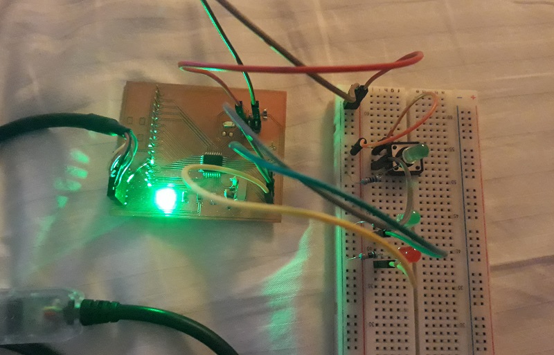
Below the working program. As you see I added a additional green Led in the electric circle of the button to show when the button is really pressed. The other green and red button are controlled by the board. That is the reason why the green LED is lighting longer than the one in the circle. Here I implemented a delay of a half second.
Potentiometer
In the next step I wanted to learn more about a analog input and how to manage it. Therefore I used the most basic input device I could find: a potentiometer. I found again a very good documentation online:HERE!The potentiometer has three pins. One VCC, one GND and one of the analog signal. Here it is important so connect this pin with one of the analog input pins of my board. Now I can use my scheme of the first part of the assignment to find the fitting analog pins.
The potentiometer generates a voltages in the range from 0 to 5V. It works as an voltage divider which is able to divide the income voltage by moving a slider or turning a button. in a potentiometer there is a resistive element on which you move a slidin contact. By changing the position of the slider you divide the complete resisor into two parts. The outcomming voltage depends on the ratio between the both single resistors. For more information click HERE!.
It is readout as a analog signal from 0 to 1023.
There was also a example code for a blinking led which blinks in the frequency of the Potentiometer, so from 0 to 1023ms delay.
int eingang= A0;
int LED = 13;
int sensorwert = 0;

void setup()
{
pinMode (LED, OUTPUT);
}

void loop()
{
sensorwert =analogRead(eingang);
digitalWrite (LED, HIGH);
delay (sensorwert);
digitalWrite (LED, LOW);
delay (sensorwert);
} int input= A0;
int LEDred = 13;
int LEDyellow = 12;
int LEDgreen = 11;
int sensorvalue = 0;
void setup()
{
pinMode (LEDred, OUTPUT);
pinMode (LEDyellow, OUTPUT);
pinMode (LEDgreen, OUTPUT);
Serial.begin(9600); //start the serial monitor. You need this code to use the monitor later
}
void loop()
{
sensorvalue =analogRead(input);
Serial.print("Sensorvalue = " ); //this is what the serial monitor shows.
Serial.println(sensorvalue); //here the monitor writes the value of the variable "sensorvalue"
if (sensorvalue > 680 ) // for the range from 680 to 1023 the green LED should turned on
{
digitalWrite(LEDgreen, HIGH); //here the green LED is turned on
}
else
{
if (sensorvalue > 340 ) // for the range from 340 to 680 the yellow LED should turned on
{
digitalWrite(LEDyellow, HIGH); //here the yellow LED is turned on
}
else // for the range less than 340 the red LEd should turned on
{
digitalWrite(LEDred, HIGH); //here the red LED is turned on
}
}
delay(100); //10 loops in a second
digitalWrite(LEDgreen, LOW); //at the end of a loop every LED is turned off
digitalWrite(LEDyellow, LOW);
digitalWrite(LEDred, LOW);
} 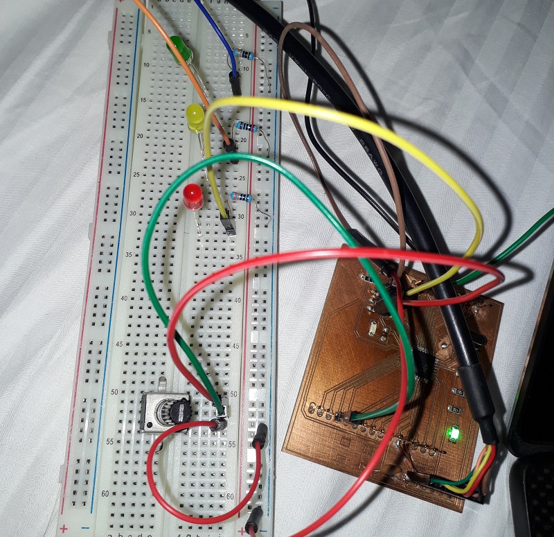
Below the working program. Ass you see on the right side the serial monitor at my laptop shows the exact value of the potentiometer and the LEDs are working like a bigger scale.
Distance measurement
In the next step I wanted to use the analog input option to measure a more real live scenario. For this case I would use a ultrasonic sensor as a distance sensor. This ultrasonic sensor is again a standard sensor of Arduino so there is a great documentation of hw to use it: HERE!The ultrasonic sensor has four pins. Again one VCC and one GND pin. Additional there is one trigger-pin and one echo-pin. With the trigger pin you are able to send ultrasonic signals and with the echo-pin you are able to detect incoming ultrasonic signals. If there is something which reflects the signal you measure the output signal after a defined period of time at the echo pin. With the measurable period of time you can calculate the distance of the reflecting object.
I used the following example to create my own distance control like you find in every new car:
int trigger=7;
int echo=6;
long dauer=0;
long entfernung=0;
void setup()
{
Serial.begin (9600);
pinMode(trigger, OUTPUT);
pinMode(echo, INPUT);
}
void loop()
{
digitalWrite(trigger, LOW);
delay(5);
digitalWrite(trigger, HIGH);
delay(10);
digitalWrite(trigger, LOW);
dauer = pulseIn(echo, HIGH);
entfernung = (dauer/2) * 0.03432;
if (entfernung >= 500 )
{
Serial.println("Kein Messwert");
}
else
{
Serial.print(entfernung);
Serial.println(" cm");
}
delay(1000);
}
int trigger=7;
int LEDred = 13;
int LEDyellow = 12;
int LEDgreen = 11;
int echo=6;
long period=0;   //initialisied a new variable named "period" with the vaule "0". "long" instead of "int" to save greater numbers, but that needs more storage
long distance=0;


void setup() //Hier beginnt das Setup.
{
pinMode (LEDred, OUTPUT);
pinMode (LEDyellow, OUTPUT);
pinMode (LEDgreen, OUTPUT);
Serial.begin(9600);
pinMode (trigger, OUTPUT);
pinMode (echo, INPUT);
}

void loop()
{

Serial.print("period = " );
Serial.println(period);
Serial.print("    " );
Serial.print("distance = " );
Serial.println(distance);

digitalWrite(trigger, LOW);
delay(5);
digitalWrite(trigger, HIGH);   //send a signal with the trigger
delay(10);
digitalWrite(trigger, LOW);
period = pulseIn(echo, HIGH);  //measure the period of time from the trigger to the echo
distance = (period/2)*0.03432; //calculate the distance in cm


if (distance > 40 )
{
digitalWrite(LEDgreen, HIGH);

else
{
  if (distance > 20 )
{
digitalWrite(LEDyellow, HIGH);
}

else
{
digitalWrite(LEDred, HIGH);
}
}

delay(500);
digitalWrite(LEDgreen, LOW);
digitalWrite(LEDyellow, LOW);
digitalWrite(LEDred, LOW);
} 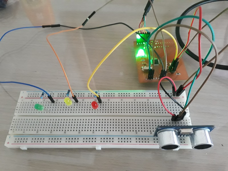
Below you can see a short clip with the working sensor. Ass you see is tracks the distance very well but it needs a plane surface of the reflecting object.
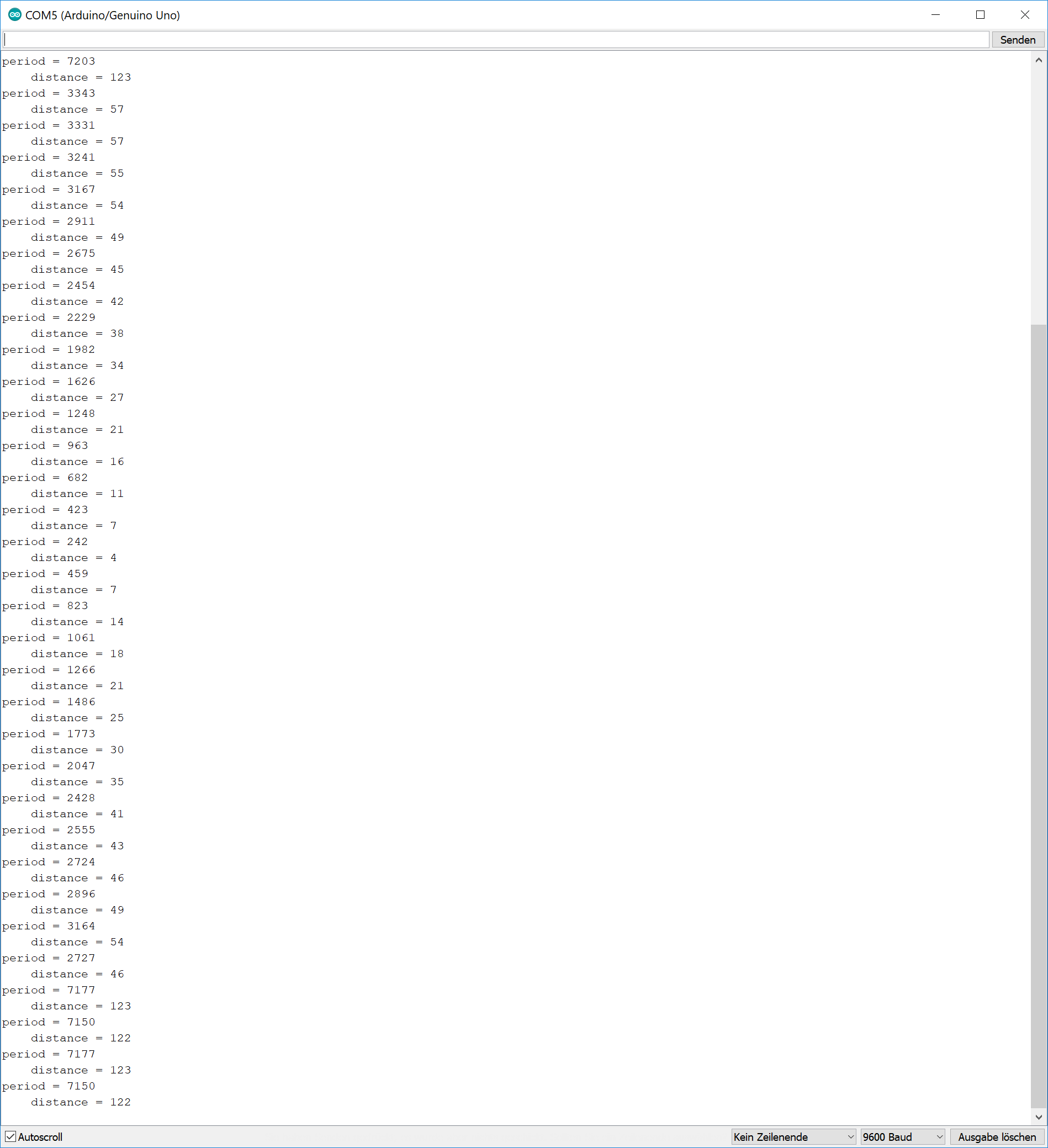
See here the serial monitor.
Additional Board Development
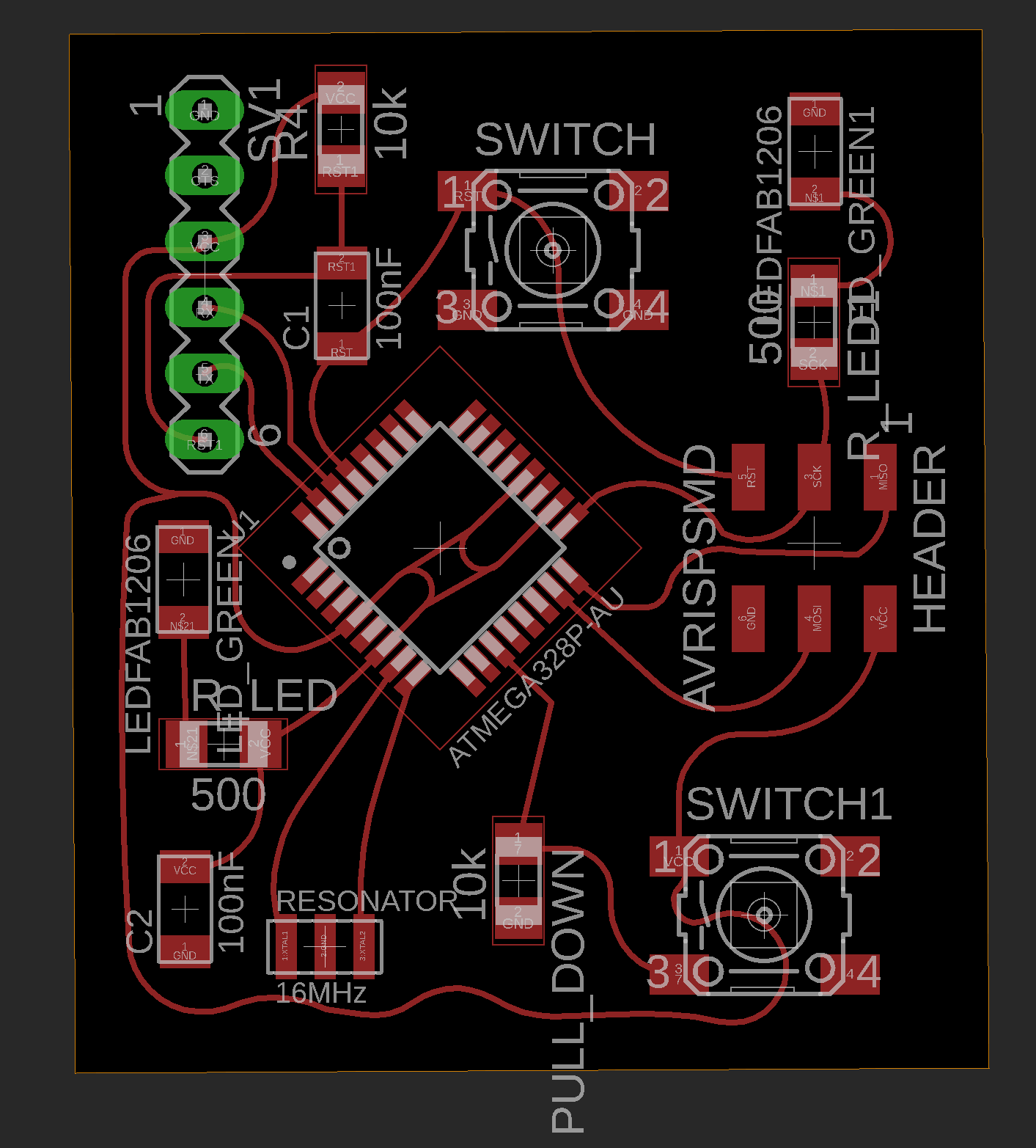
To show my design and production skills I developed a new micrrocontroller board for this week. See here my final layout.It is a simple board with a button as a input device. There are additional LEDs on it to show the functionality on a simple way. See the scheme below:
This time tried a different types of routes. See the final design below:
The first milling process failed as you see in the picture below. After a short research i found the mistake: The tool was outworn.
.jpeg)
See here the final milled board next to the first failed one.
.jpeg)
See here the functional test. By pushing the button the greed LED will light up for 5 secounds:
Downloads
| Arduino Programs | download |
| Boarddesigns | download |
