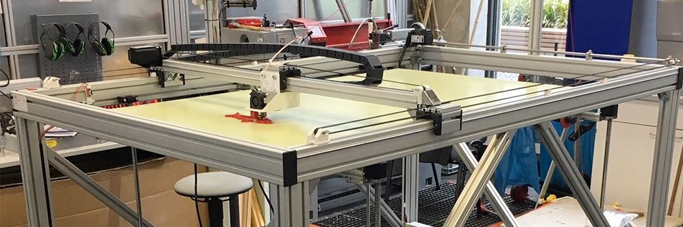
Big 3D-Printer
With a maximum volume of 150 x 90 x80 cm
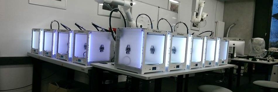
Some of our Ultimaker
We´ve got more than 25 3D-Printer of diffrent types

Greeting
Our best employee in HRW FabLab
Assignment 8:
embedded programming
Task:
- experiment with other architectures(group project)
- read a microcontroller data sheet
- program your board to do something, with as many different programming languages and programming environments as possible
Work
The following assignment is based on the Atmel ATmega328. The reason I chose this controller is that this controller is also used in the Arduino boards and this controller also should be strong enough to solve all my needs. I also can use the arduino interface to load my selfdeveloped boards. For me as a noob in informatics thats a great option. So let´s first take a look inside the datasheet:At the beginning of each datasheet you can find a list of features the controller has and some important info about the performance. In the following the list of features of the Atmega328P:
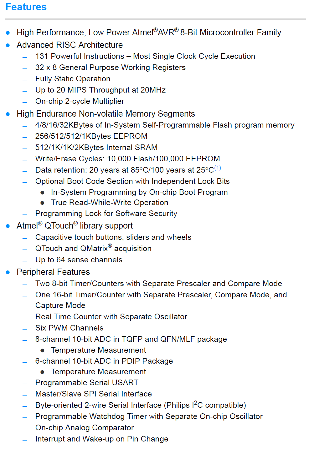
This info are important to decide of the controller is able to solve the problems of the project you want to start.
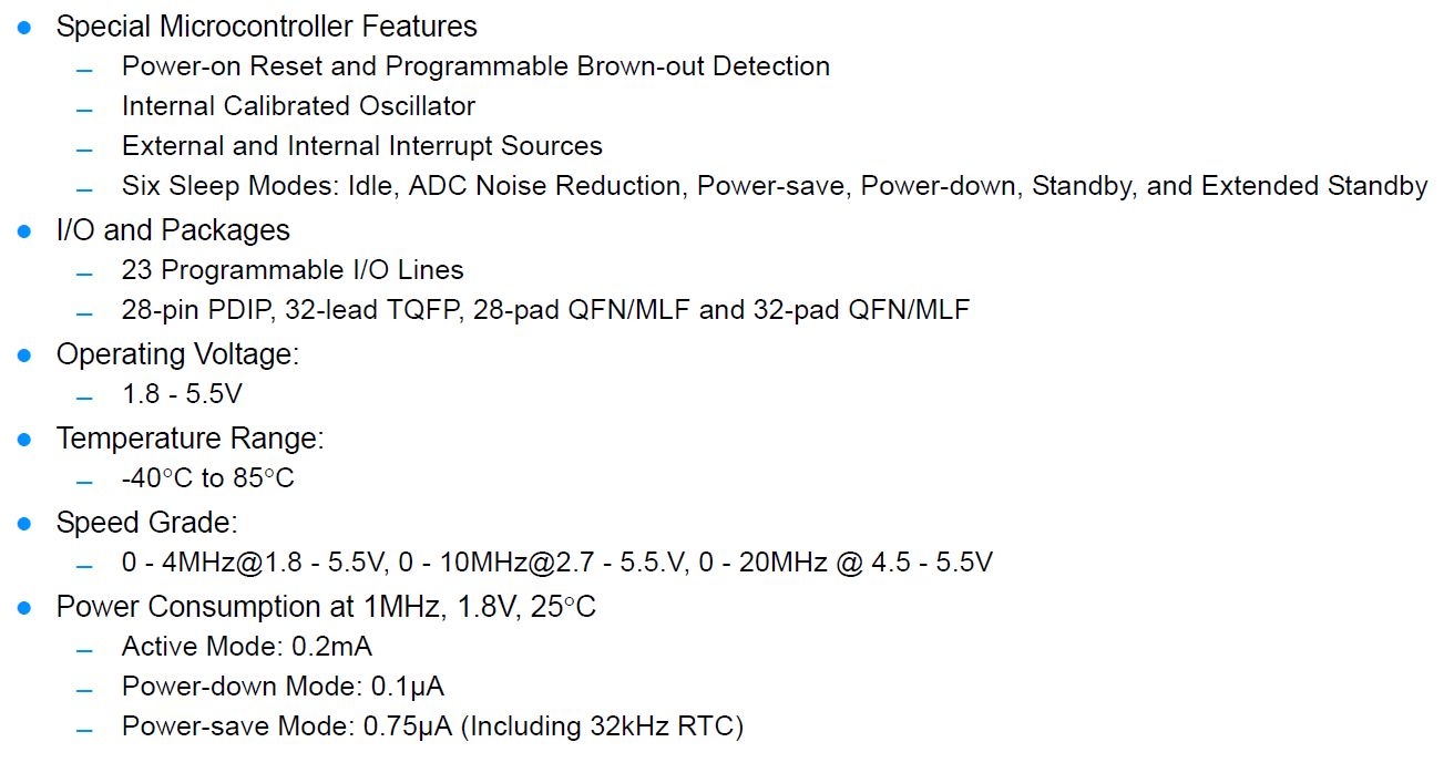
This info are important to decide of the controller is able to solve the problems of the project you want to start. On the next side you can find the physical properties like the operating voltage or temperature range. This is also important to plan the infrastructure of your board and the necessary voltage source.
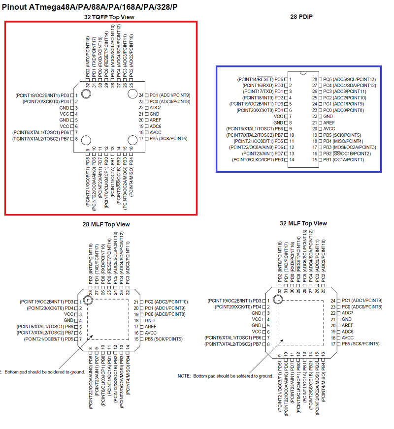
There are different building types of a Atmega328P. For my own board I used the layout in the red box. Arduino used the PDIP Layout with only 28 pins on the One boards.
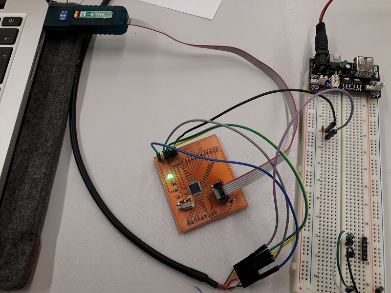
I used this board to test my programming code before using my own developed board. So I can find mistakes in my code before searching for mistakes in the board design.
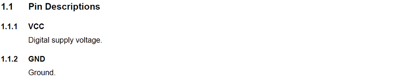
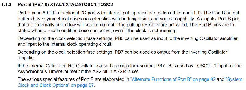
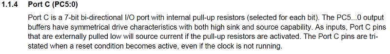
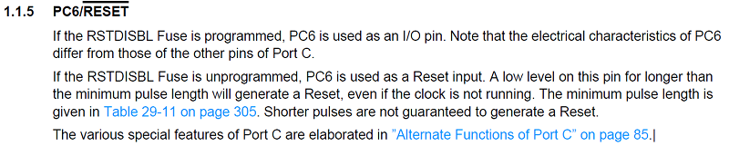
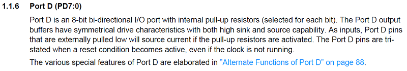
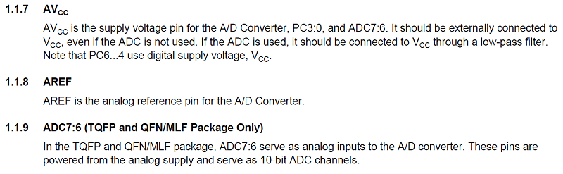
This special controller offers three different types of pins. Port B, C and D. At this point of the datasheet you find only quite rudimentary info about the single pin, but there is always a link to the complete description of each pin and how to use them. Additional there are different types of voltage pins which allows extra functions.
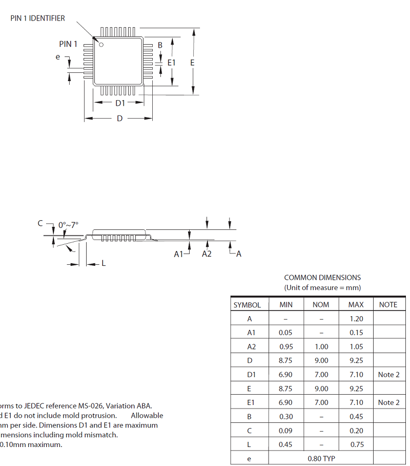
You also can find a description of all measures of the physical pin. You need this info for the footprint. Here you find all necessary measures of the single pins and the distances.
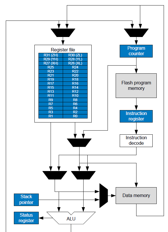
See in the next picture the internal layout of the controller. The Atmega328P works with 32 registers. With this picture it is able to understand the internal process of the controller.
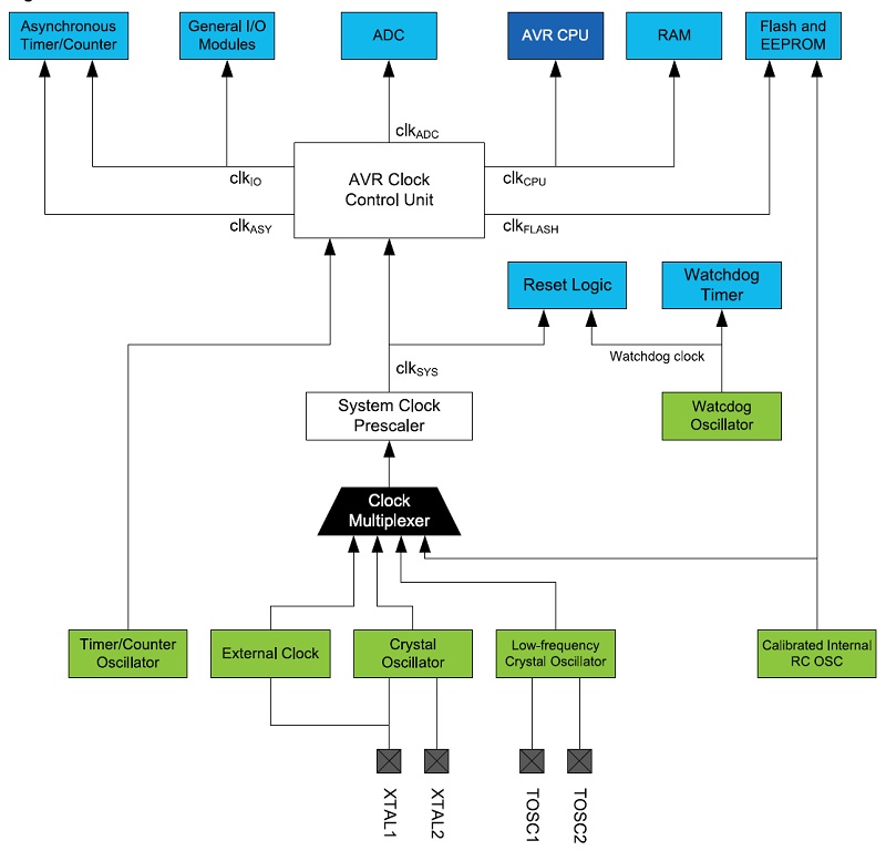
In the next step you also can find all info about the different types of use of a clock. There is a system clock inside the controller but there are also different options to add a external clock. The figure below shows the options and also the process at the inside of the controller. So for example here I found the info about which pins I had to use to connect my external resonator(XTAL1 and XTAL2).
After this first overview of information and ideas how to work with the datasheet of a microcontroller I used this datasheet in the following assignments nearly every week with programming workload. See the following assignments I used the datasheet again:
- 10. input devices
- 11. output devices
- 12. interface and application programming
- 13. networking and communications
- 10. input devices
- Electricity
Programming the board
Cause my programming skills are very rudimentary I wanted to start with a simple program and then go on step by step. So I also started first with the Arduino to check if everything works before using my own developed board. See here the first step with a blinking led.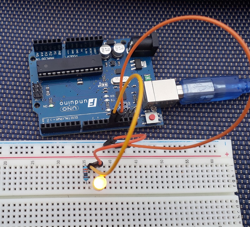
Arduino Program
int ledPin = 13;                //initialize the 13. pin and name it "ledPin"

void setup() {                  //set the setup
pinMode(ledPin, OUTPUT);        //declare the "ledPin" as a output pin
}
    void loop()                     //set the loop
{
digitalWrite(ledPin, HIGH);     //set the "ledPin" to high
delay(1000);                    //wait 1000ms /1s
digitalWrite(ledPin, LOW);      //set the "ledPin" to low
delay(1000);                    //wait 1000ms /1s
}                               //begin the loop again
C Program
To programm a board with C as programming language you have to know about the architecture of a microcontroller. Here the single pins are not simply numbered and you also cant set them easily to "high" or "low" as you do it in the arduino IDE. Because I´d like to use the Arduino IDE also to program with C as programming language I had to insert a special library to read the C code. I chose the arduino IDE as my favorite programming programm bacause here i had some pre experiences and was able to focus on the C language. Later I´ll show you how to programm your board with atmel studio.See here a first simple blinking C programm and the explanation below:
#include <stdio.h>           //include the libary for reading C
#include <avr/io.h>
#include <util/delay.h>      //include the function "delay"

int main (void) {                 //that is the main program

  DDRB |= 0B00100000;             //activate the 5. PB pin

while(1){                         //that is the loop program which starts again after finishing
  PORTB |= 0B00100000;            //set the 5. PortB pin to high
  _delay_ms(1000);                //wait 1000ms /1s
  PORTB &= 0B11011111;            //set the 5. PortB pin to high
  _delay_ms(1000);                //wait 1000ms /1s
  }
  }
#include <stdio.h>
#include <avr/io.h>
#include <util/delay.h>
These libraries are necessary to use the arduino IDE to programm my board. The stdio library is needed to "understand" the the C programmm also in the arduino IDE.the avr.io library is necessary to define the ports and pins of an microcontroller with avr architecure.
The delay library allows to use the comand "_delay_ms()" i liked to use in the code.
DDRB
"DDR" stands for "Data-Direction-Register" and the following letter discribes the port. Here you are able to set the single pins to input or output ports.|= / &=
With this functions you are able to set or delete single ports and pins. With |= you can set the defined pin and with &= you can delete it.0B00100000
This phrase descripe which pin you like to set. IN the Datasheet you can find the following explanation of how to adress the single pins. To adress the 5. pin, you have to change the 5. 0 from behind to 1. We just want to set this single pin, so we don´t need to adress more than this shown pin.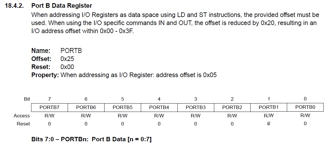
There is another way to descripe the pin:
(1 <<PB5)
this phrase would do the same, it is only a different way to write it. Also here you set the pin PB5 to 1.
PORTB
With this function you are able not only to activate a pin but also to set it high or low. The adressing auf the pin is the same as in the DDR comand._delay_ms()
This function is a simple delay function which let your program "wait" for the defined time in ms in the brackets.After checking this small blinking programs I started to program my own board. As you see I found one problem with a missing capacitor. Also I noticed that I inverted the RX and TX pin at the FTDI-cable so I had to use a separate cables to get the right connection. After these small fixes the codes also works at my own board.
additional new C-Program
To show how to work with different ports and registers I decided to write my own more complexe C Programm. See here the program with the additional description:#include <stdio.h>
#include <avr/io.h>
#include <util/delay.h>
int main (void) {
DDRB |= (1 <<PB1); //activate the 1. PB pin of Port B
DDRC |= 0B00000100; //activate the 2. PB pin of Port C
DDRD |= 0B00100000; //activate the 5. pin of Port D
while(1){ //that is the loop program which starts again after finishing
PORTB |= (1 <<PB1); //set PB1 to high
PORTC |= 0B00000100; //set PC2 to high
PORTD |= 0B00100000; //set PD1 to high
_delay_ms(500); //wait 0.5 seconds
PORTB &= (0 <<PB1); //set PB1 to low
_delay_ms(500); //wait 0.5 seconds
PORTC &= 0B11111011; //set PC2 to low
_delay_ms(500); //wait 0.5 seconds
PORTD &= 0B11011111; //set PD1 to low
_delay_ms(1000); //wait 1 second
}
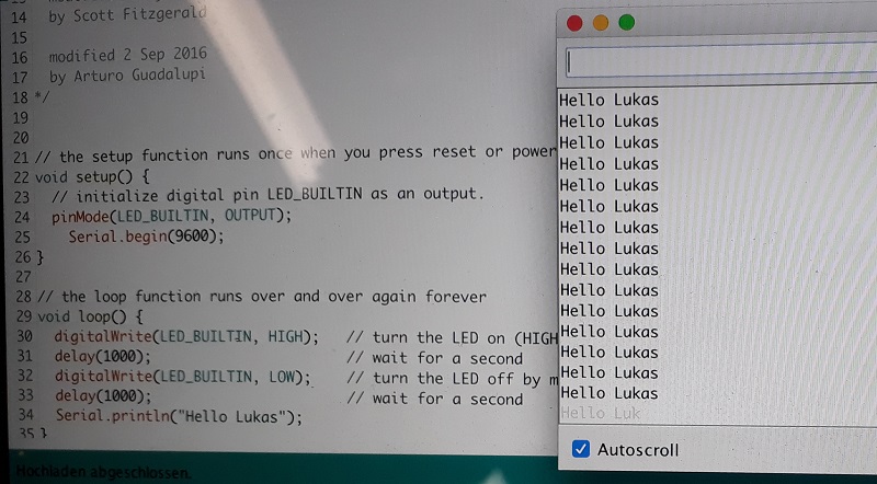
} With these fixes also the “Hello World” program works at my board. So I updated my board layout and build a new working one.
Additional I installed Atmel Studio 7 to programm my own board. It is a very powerfull programm so programm nearly any controller with diffrent languages. So I tried to programm my own board also with the blinking LEd programm with Atmel Studio. See the working programm under downloads.
To use Atmel Studio also for the Arduino Framework there is a way to insert the Arduino bootloader. It is a little bit tricky so I want to explain in a few steps:
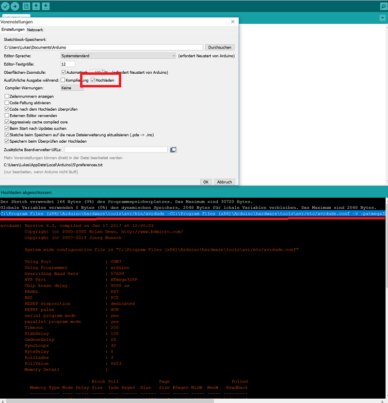
First activate the option in Arduino settings in the red box of the picture. Then upload any programmcode with the Arduino framework and open the console. Here you find the link over the red line. This link you need in the next step in Atmel Studio.
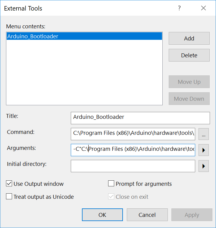
Here add a external tool and paste the link in the fields like in the picture below.
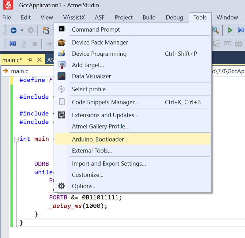
Now there is a new tool with which you can use Atmel Studio also with the arduino bootloader and code like you do in the Arduino framework. So it is quite simple to use Atmel Studio for all types of controller and programming languages.
But why using C as programming language? I heard that the Arduino language is quite more slowly and so there are often problems with fast programs like for motors. I wanted to see the difference so I used the blinking program and connected the output pin with the oscilloscope.

Here you see the voltage jump from high to low of the Arduino program. It jumps between the two orange marks. It is a time span from more than 11.5 uS. So the signal isn´t precise at all. To control a motor or another dynamic system it wont work well. So lets try the same program with C language:
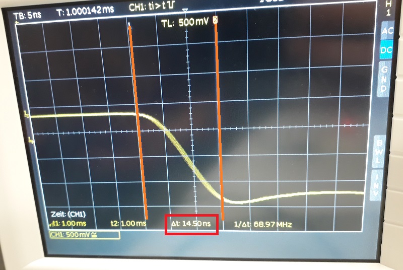
As you see in this picture the jump is quite more precise. I had to zoom in to realize a small flickering. As the orange marks show the complete jump only needs 14.5 nS. So the C language is quite more dynamic. To control a motor the C language will be the better choice.
Downloads
| Datasheet AtMega328P | download |
| Arduino Program LED blink | download |
| C Program LED blink | download |
| Atmel Studio Program LED blink | download |
