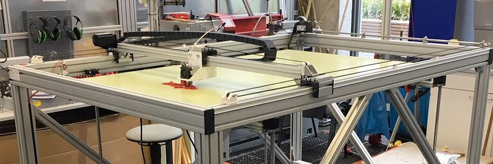
Big 3D-Printer
With a maximum volume of 150 x 90 x80 cm
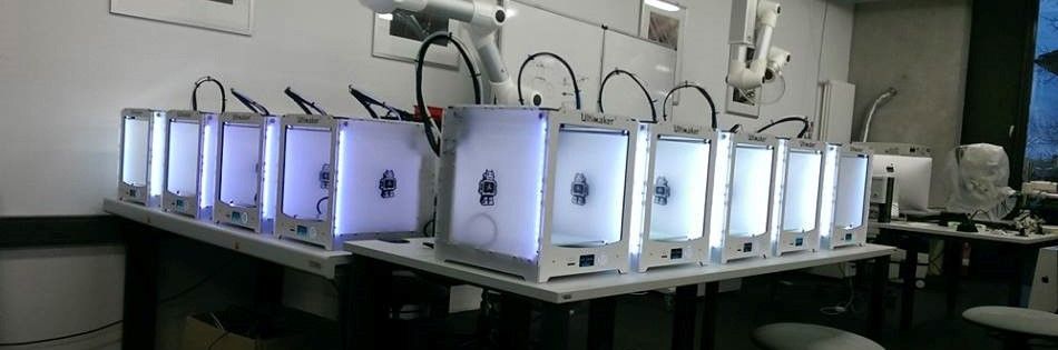
Some of our Ultimaker
We´ve got more than 25 3D-Printer of diffrent types
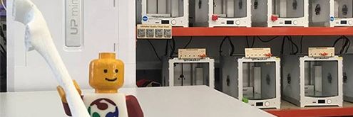
Greeting
Our best employee in HRW FabLab
Final Project
Hardware
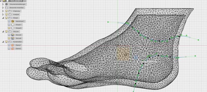
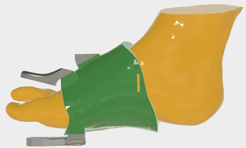
With my aim of my final project to show the potentials of a FabLab especially for people with disabilities I started the hardware design with a scan of my foot. Here my college peter helped me, because its impossible to scan his own foot with a hand-operated 3D-scanner. The generated .obj file I opened in meshmixer. Here I fixed some small errors in the 3d object and added a plain cut. See the scan below.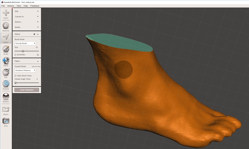
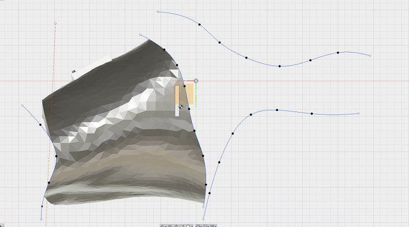
Now I opened the file in fusion because I wanted to design a individual holding around the 3D-scan. To do so I had to generate a model out of the .obj file. Fusion is only able to handle up tp 10.000 surfaces to generate a model so I had to reduce my file. At the beginning there are more than 150.00 surfaces so I badly loosed a lot if accuracy but the result also looks nice. To get a fitting holding I generated a offset to my real scan and divided the scan. Now I cut with splines all unnecessary parts.
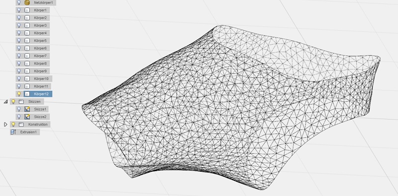
See here the first design of the holding.
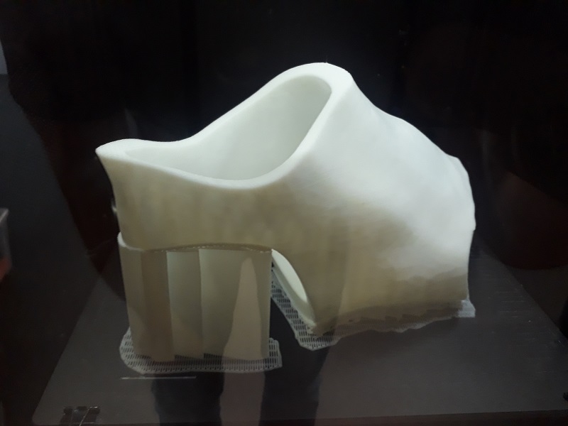
To test the accuracy of fit I 3d printed this design. I needs a lot of support structure but the result looks quite good.
The first idea was to print the holding in flexible material so you can put it on like a sock. But after the first tries with flexible materials I noticed, that I need hard parts to get reproduceable data of the motion sensor and also to install the necessary buttons. The connection of flexible and inflexible material wont work well. See here the fitting of the holding.
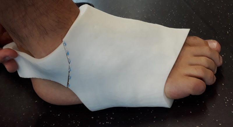
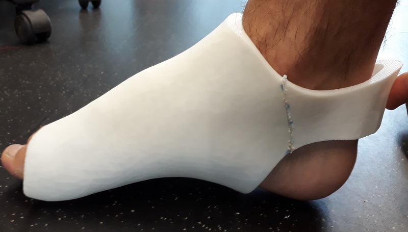
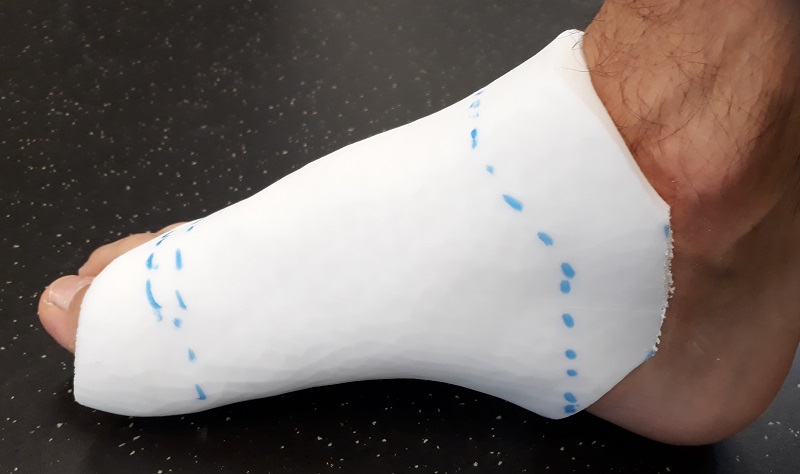
The holding fits perfectly but I noticed it fits to good to get the necessary moving space. So with the holding on I´m unable to rotate or tilt my foot. So I had to update the design to get the needed free space. See in the picture below the disturbing parts.
See here the updated holding also included two holes for a elastic band to keep the holding in position.
Here I also added the plate for the sensor to get a plain surface.
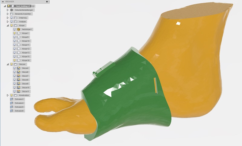
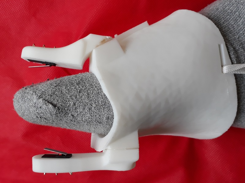
In this picture you see the complete system with the additional adapter for the sensor an the addons for the necessary button i´d like to control with my big toe. Also here they are developed around the 3D-scan so they are absolutely fitting to my individual foot geometry.
See here the finished 3D-print. It fits perfectly and the buttons are easy to reach but not to close to activate them by mistake.
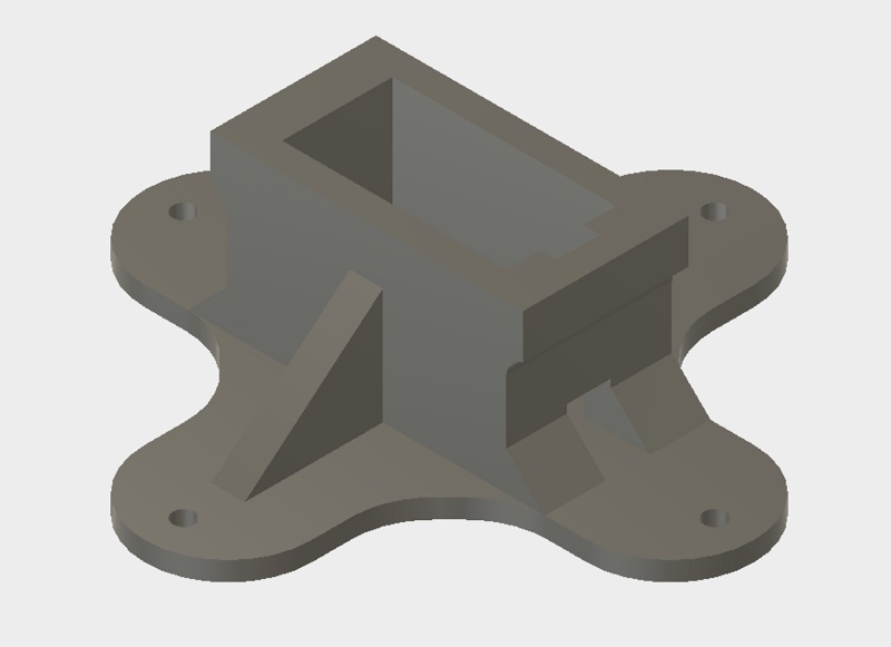
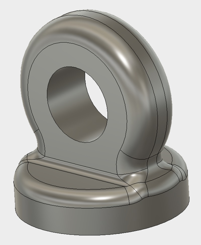
in the next step I need to design my robot arm. As you see in the concept I need to design several parts. The first stage is the base of the robot arm. See the design below:
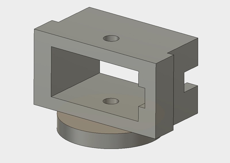
At the top of the first servo the second stage is installed. As you see I´m able to use always the same frame for the servos. As I tested before the servos fits perfectly in this frame so there are no additional screws or glue needed.
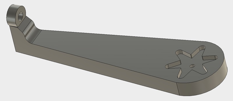
The next stage is the first part of the real arm. At the end you are able to install the third servo. Especially this part could be used more than one time to get more degrees of freedom.
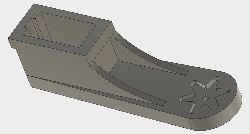
The final stage contains the holding for the vacuum cup.
The following part is needed to direct the vacuum flexible tube to avoid folding.
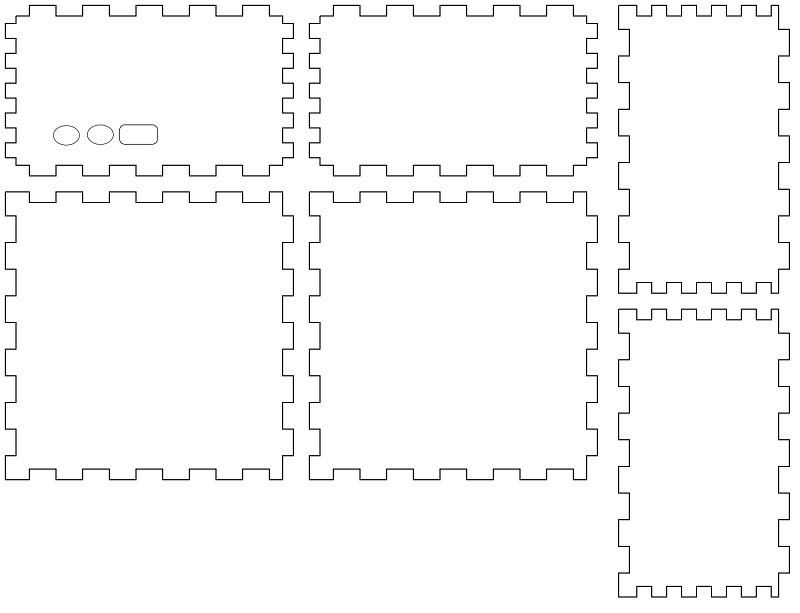
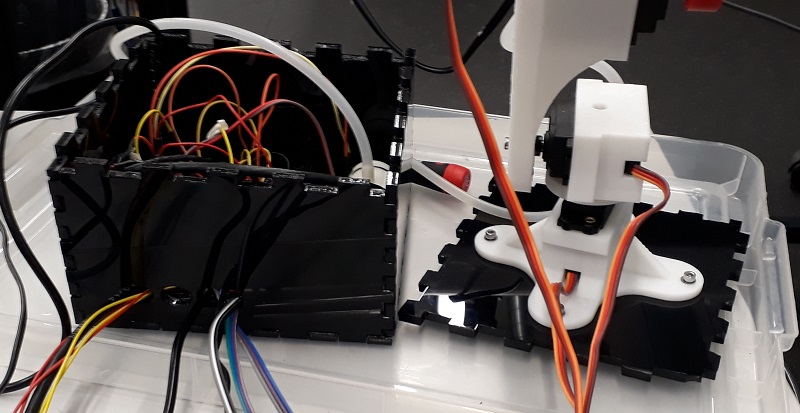
Additional to the 3d printed parts I designed a simple box to keep the electrical parts in it. Here I used peters box generator and added the necessary holes.
See here the finished box cut out of black acryl. The robot arm could be added on top to get a fix standing.
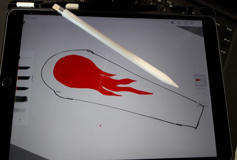
In addition to the mechanical parts I wanted to add some optical features. So I designed some super cool flames with my digital sketchbook.
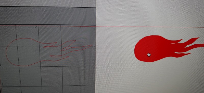
In the next step I prepared the file to cut it in vinyl.
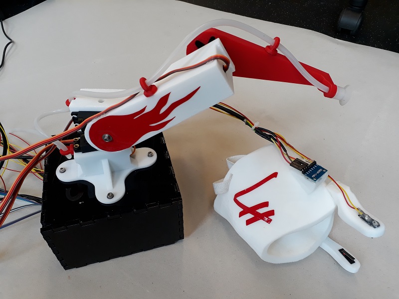
See here our vinyl cutter doing his job. I also added some “LH” tags to show the individuality of this project.
See here the final hardware setup. A lot of 3D and 2D design with a lot of different tools and technologies.
Downloads
| Holding data | download |
| Robot arm data | download |
| Box data | download |
