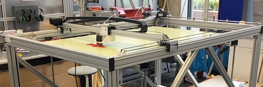
Big 3D-Printer
With a maximum volume of 150 x 90 x80 cm
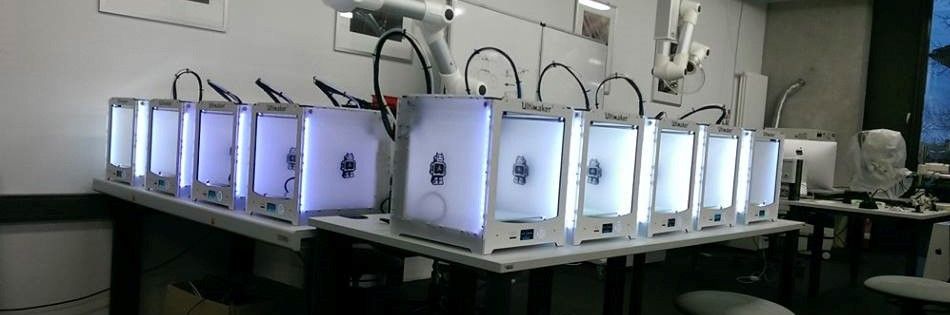
Some of our Ultimaker
We´ve got more than 25 3D-Printer of diffrent types
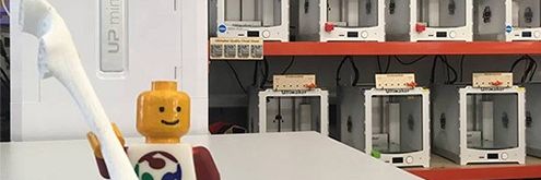
Greeting
Our best employee in HRW FabLab
Final Project
Electricity
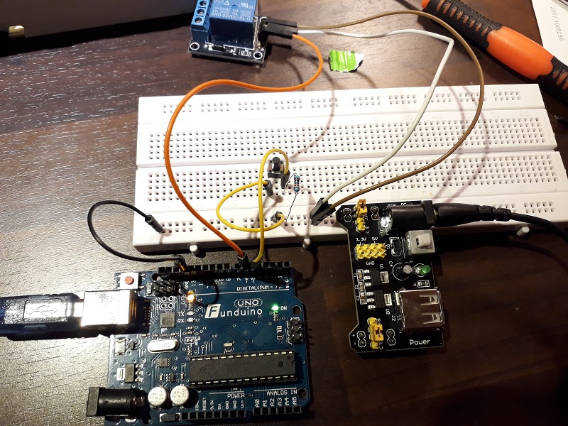
For the electrical part I divided the complete system in some subsystems to get the single parts work. Some parts were new for me so I had to test them before. For example the relay needed to be tested. In the first step I used an Arduino to make the first tests and to develop a scheme for my own board. It makes more sense to build the complete system and develop a PCB with the finished scheme than making a new one for every single step.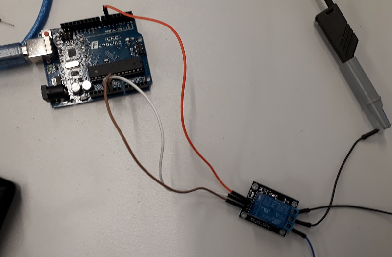
After testing the relay, I added a button to simulate the button at my foot holding. This button should start the vacuum pump to grap objects with the robot arm.
In the next step I added the sensor and the servos. It was a lot of work to generate repeatable sensor data and transform them into moving operations. As you see in this stage I used a breadboard to wire the single parts. In the final project I wanted to find a more professional solution.
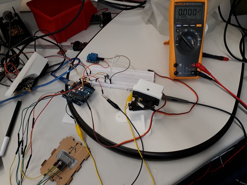
See here the first moving test with the combination of the sensor an the servos.
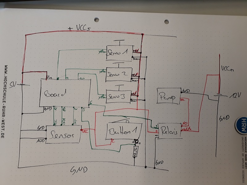
Take a look at my scheme. It becomes more complex with every new part. This is a intermediary result. There is a second button missing which interrupts the robot motion and some pull-down resistors for the I2C communication of the sensor to enable longer wires.
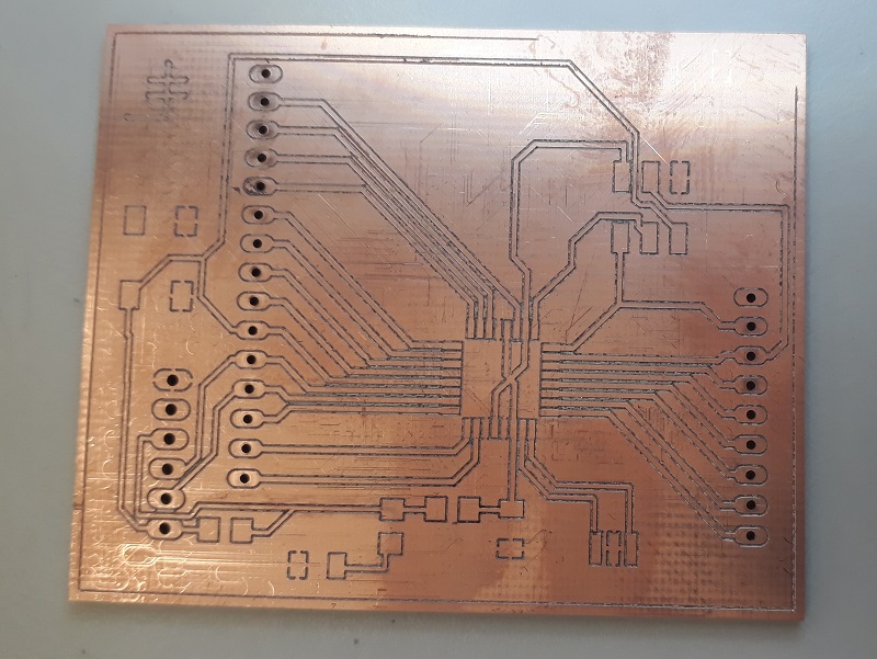
After finishing the scheme I started the PCB production. I decided to build a “standard” PCB to enable the development of the complete system. In my mind I will create a platform with my final project with which anybody who is interested in could build his own systems. So my PCB allows to add different parts and has enough free ports to make the systems more complex in the next stages.
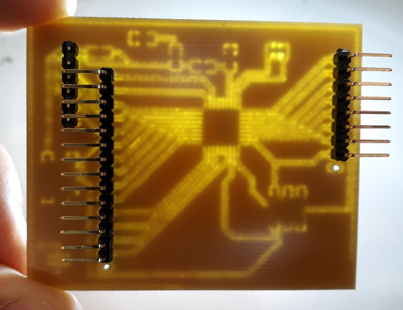
See here the milled board. During the postprocess I found a bridge in the layout but with a sharp knife I could fix it.
I decided to divide the programming and the programmable ports so my board gets his pins at its back. That also makes the box looks more sorted.
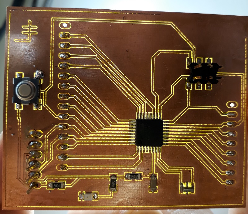
See here the front of my board. I also added my LH sign.
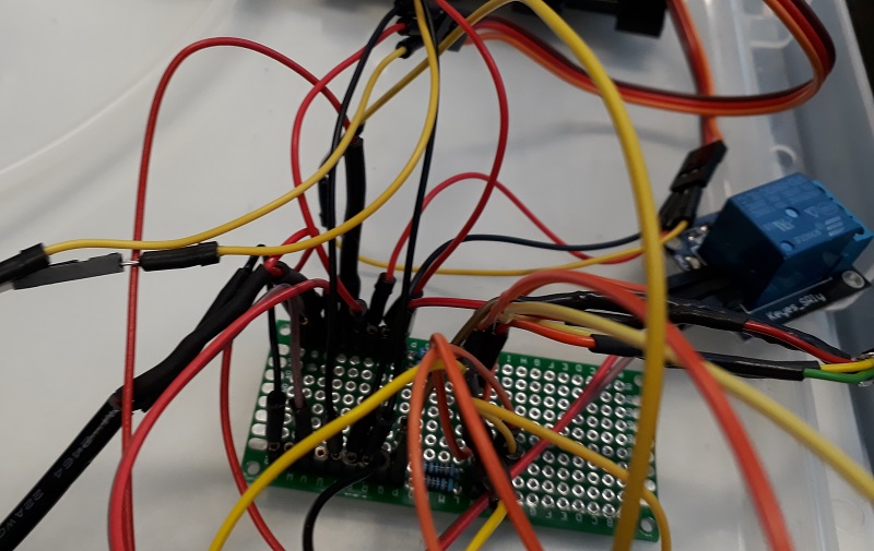
To order and wire the mass of cables I added a second board. These boards are designed and build quite fast so for developing a individual assistant system at the platform of my final project you don´t need to have a PCB milling machine. Just solder the individual parts by yourself.
Finally I added two dip switch to activate the voltage source for the 12V pump and the 5V for the rest of the system.
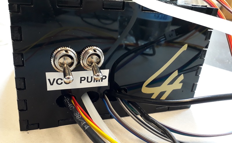
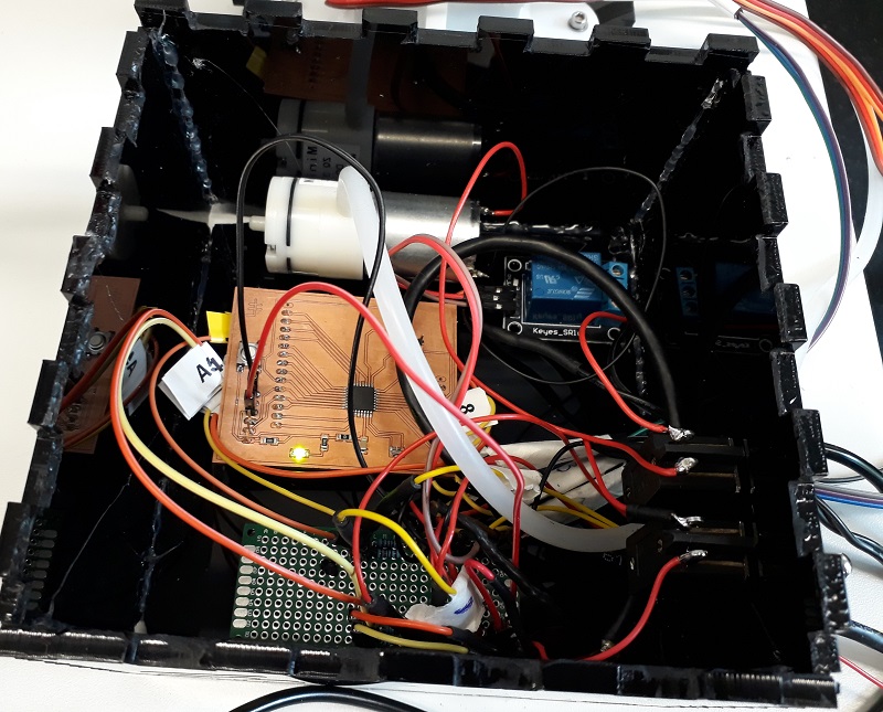
Take a look inside the black box. Looks pretty unordered but it works 😉
After wiring all the parts and put them together let´s make them move in the software part
Update
To join the electronic components I decided to design and fabricate a new board especily for my final project. The design and layout process is the same as I showed befor in Week 04 and Week 06.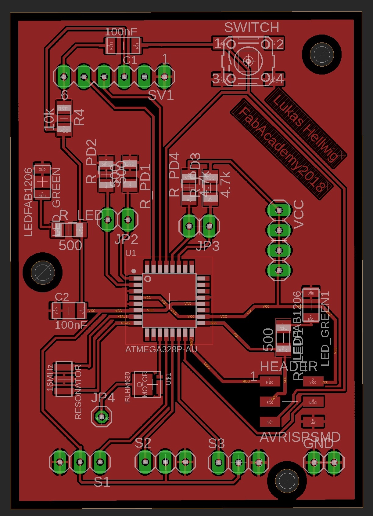
In the first step the DRC noticed a problem with my label, but that is not critical and could be deleted.
.jpg)
See here the partlist of my Board.
.jpg)
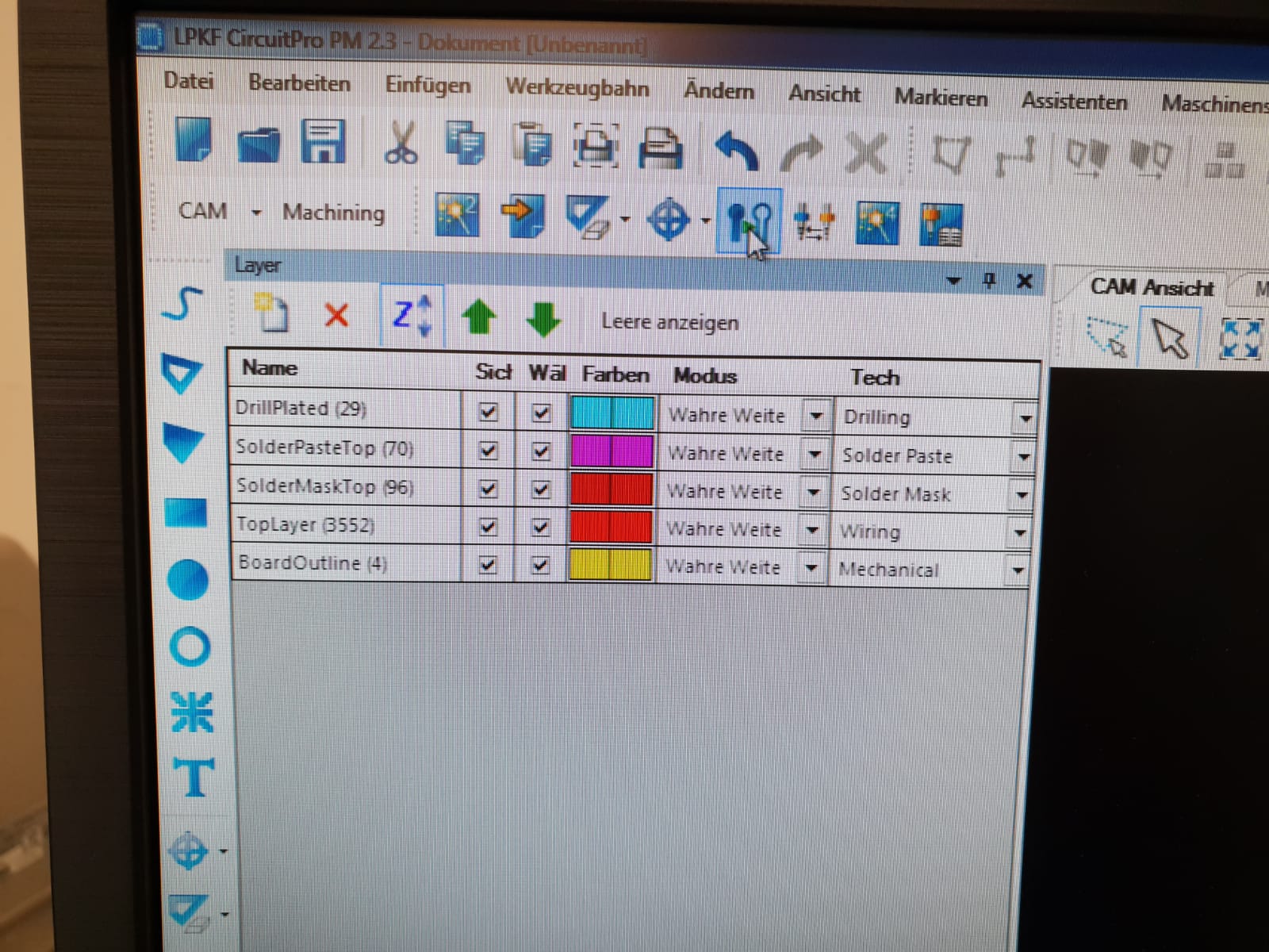
Here you see the layer setings durig the preprocess of the milling. Here I only had to deleted the empty layer to avoid problems.
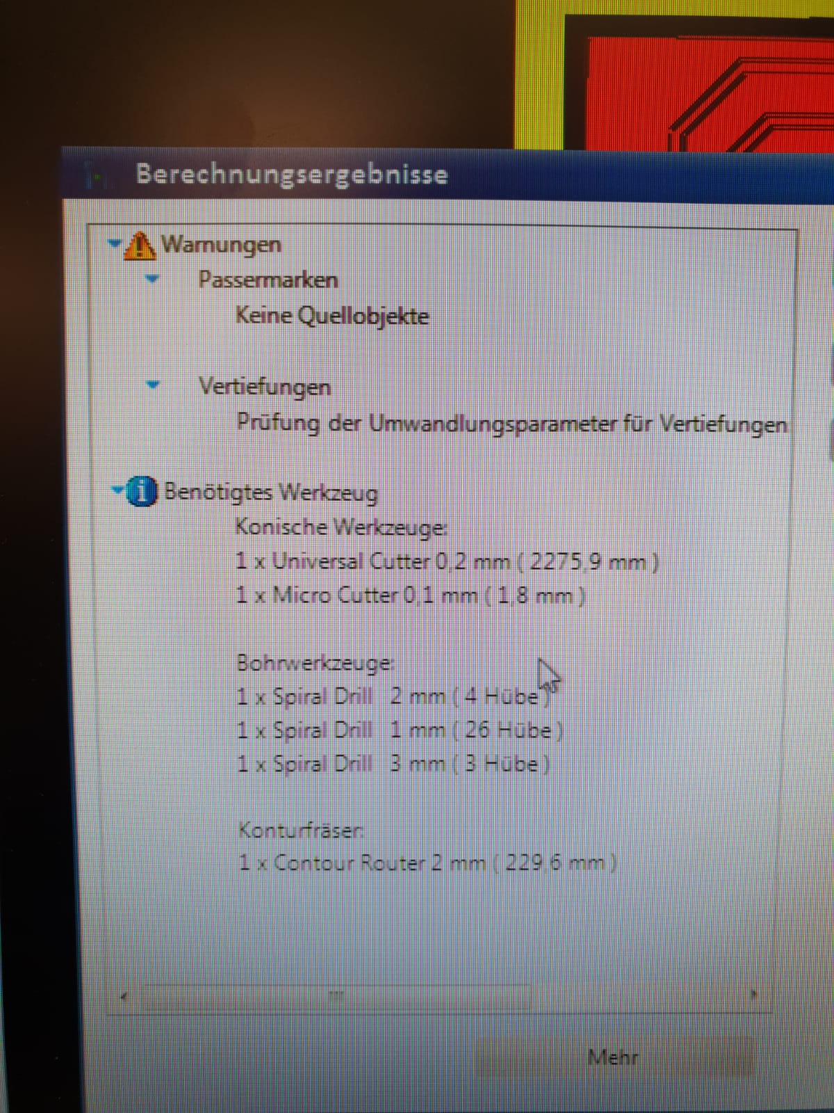
The result of the calculation process with the necessary tools.
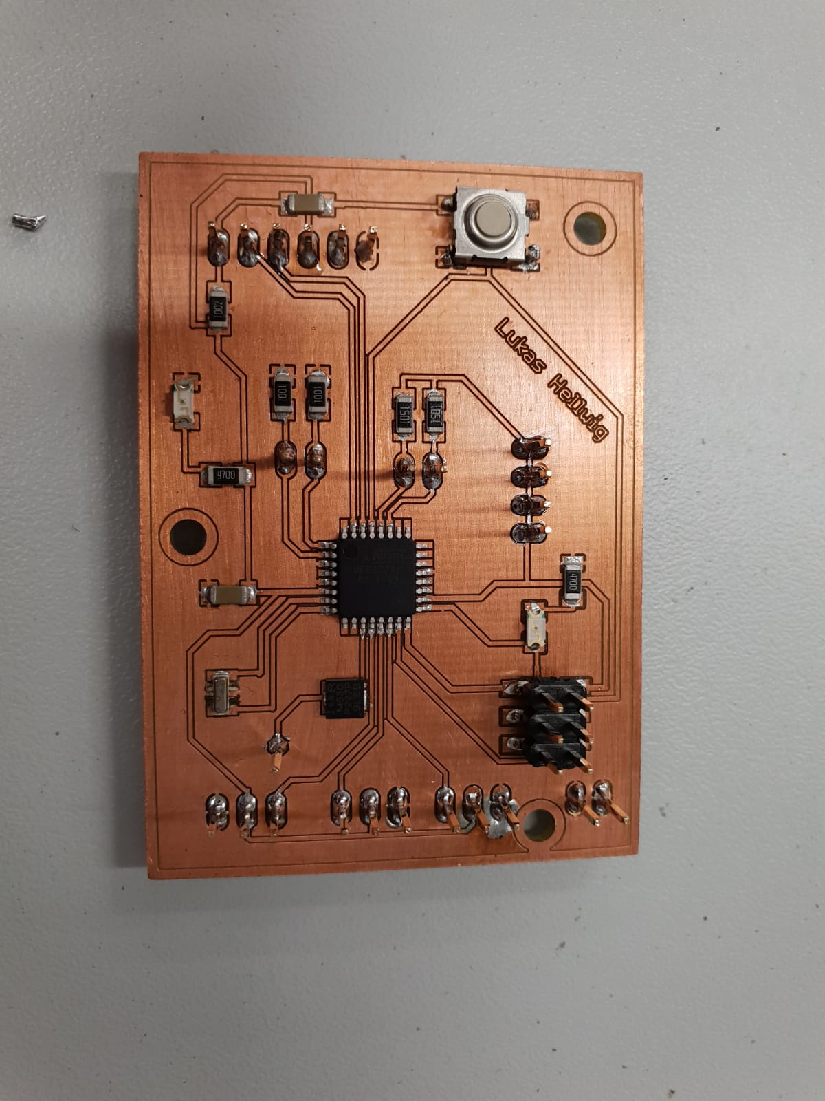
After placing the electronic components my Board looks like this:
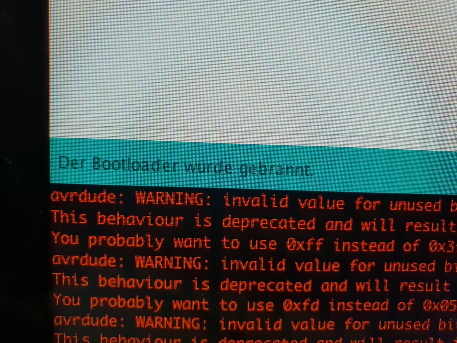
Burning the Bootloader works by the first try.
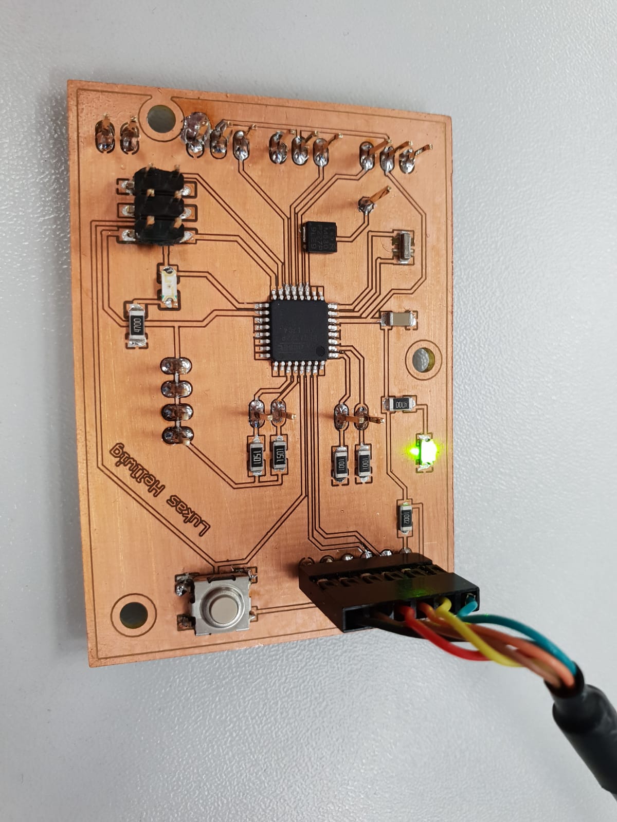
See here the working Board:
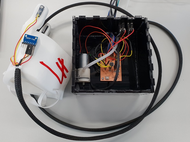
See here the complete intergrated system. The new board makes the wireing a lot more easy and good locking. The addition holes in the boards makes it possible to use screws to fix the board. The pump is hold in place with some small points of glue.
Downloads
| Board data | download |
| Final Board 2.0 | download |
